EP4495351A1 - Élément de façade préfabriqué, système de façade ainsi que procédé de fabrication d'une façade isolée - Google Patents
Élément de façade préfabriqué, système de façade ainsi que procédé de fabrication d'une façade isolée Download PDFInfo
- Publication number
- EP4495351A1 EP4495351A1 EP24182758.3A EP24182758A EP4495351A1 EP 4495351 A1 EP4495351 A1 EP 4495351A1 EP 24182758 A EP24182758 A EP 24182758A EP 4495351 A1 EP4495351 A1 EP 4495351A1
- Authority
- EP
- European Patent Office
- Prior art keywords
- facade
- facade element
- supporting structure
- layer
- carrier plate
- Prior art date
- Legal status (The legal status is an assumption and is not a legal conclusion. Google has not performed a legal analysis and makes no representation as to the accuracy of the status listed.)
- Pending
Links
Images


Classifications
-
- E—FIXED CONSTRUCTIONS
- E04—BUILDING
- E04F—FINISHING WORK ON BUILDINGS, e.g. STAIRS, FLOORS
- E04F13/00—Coverings or linings, e.g. for walls or ceilings
- E04F13/02—Coverings or linings, e.g. for walls or ceilings of plastic materials hardening after applying, e.g. plaster
- E04F13/04—Bases for plaster
-
- E—FIXED CONSTRUCTIONS
- E04—BUILDING
- E04F—FINISHING WORK ON BUILDINGS, e.g. STAIRS, FLOORS
- E04F13/00—Coverings or linings, e.g. for walls or ceilings
- E04F13/07—Coverings or linings, e.g. for walls or ceilings composed of covering or lining elements; Sub-structures therefor; Fastening means therefor
- E04F13/08—Coverings or linings, e.g. for walls or ceilings composed of covering or lining elements; Sub-structures therefor; Fastening means therefor composed of a plurality of similar covering or lining elements
- E04F13/0801—Separate fastening elements
- E04F13/0832—Separate fastening elements without load-supporting elongated furring elements between wall and covering elements
- E04F13/0857—Supporting consoles, e.g. adjustable only in a direction parallel to the wall
-
- E—FIXED CONSTRUCTIONS
- E04—BUILDING
- E04F—FINISHING WORK ON BUILDINGS, e.g. STAIRS, FLOORS
- E04F13/00—Coverings or linings, e.g. for walls or ceilings
- E04F13/07—Coverings or linings, e.g. for walls or ceilings composed of covering or lining elements; Sub-structures therefor; Fastening means therefor
- E04F13/08—Coverings or linings, e.g. for walls or ceilings composed of covering or lining elements; Sub-structures therefor; Fastening means therefor composed of a plurality of similar covering or lining elements
- E04F13/0866—Coverings or linings, e.g. for walls or ceilings composed of covering or lining elements; Sub-structures therefor; Fastening means therefor composed of a plurality of similar covering or lining elements composed of several layers, e.g. sandwich panels or layered panels
-
- E—FIXED CONSTRUCTIONS
- E04—BUILDING
- E04F—FINISHING WORK ON BUILDINGS, e.g. STAIRS, FLOORS
- E04F13/00—Coverings or linings, e.g. for walls or ceilings
- E04F13/07—Coverings or linings, e.g. for walls or ceilings composed of covering or lining elements; Sub-structures therefor; Fastening means therefor
- E04F13/08—Coverings or linings, e.g. for walls or ceilings composed of covering or lining elements; Sub-structures therefor; Fastening means therefor composed of a plurality of similar covering or lining elements
- E04F13/0875—Coverings or linings, e.g. for walls or ceilings composed of covering or lining elements; Sub-structures therefor; Fastening means therefor composed of a plurality of similar covering or lining elements having a basic insulating layer and at least one covering layer
-
- E—FIXED CONSTRUCTIONS
- E04—BUILDING
- E04F—FINISHING WORK ON BUILDINGS, e.g. STAIRS, FLOORS
- E04F13/00—Coverings or linings, e.g. for walls or ceilings
- E04F13/07—Coverings or linings, e.g. for walls or ceilings composed of covering or lining elements; Sub-structures therefor; Fastening means therefor
- E04F13/08—Coverings or linings, e.g. for walls or ceilings composed of covering or lining elements; Sub-structures therefor; Fastening means therefor composed of a plurality of similar covering or lining elements
- E04F13/0889—Coverings or linings, e.g. for walls or ceilings composed of covering or lining elements; Sub-structures therefor; Fastening means therefor composed of a plurality of similar covering or lining elements characterised by the joints between neighbouring elements, e.g. with joint fillings or with tongue and groove connections
- E04F13/0894—Coverings or linings, e.g. for walls or ceilings composed of covering or lining elements; Sub-structures therefor; Fastening means therefor composed of a plurality of similar covering or lining elements characterised by the joints between neighbouring elements, e.g. with joint fillings or with tongue and groove connections with tongue and groove connections
-
- E—FIXED CONSTRUCTIONS
- E04—BUILDING
- E04F—FINISHING WORK ON BUILDINGS, e.g. STAIRS, FLOORS
- E04F13/00—Coverings or linings, e.g. for walls or ceilings
- E04F13/07—Coverings or linings, e.g. for walls or ceilings composed of covering or lining elements; Sub-structures therefor; Fastening means therefor
- E04F13/08—Coverings or linings, e.g. for walls or ceilings composed of covering or lining elements; Sub-structures therefor; Fastening means therefor composed of a plurality of similar covering or lining elements
- E04F13/0889—Coverings or linings, e.g. for walls or ceilings composed of covering or lining elements; Sub-structures therefor; Fastening means therefor composed of a plurality of similar covering or lining elements characterised by the joints between neighbouring elements, e.g. with joint fillings or with tongue and groove connections
- E04F13/0898—Coverings or linings, e.g. for walls or ceilings composed of covering or lining elements; Sub-structures therefor; Fastening means therefor composed of a plurality of similar covering or lining elements characterised by the joints between neighbouring elements, e.g. with joint fillings or with tongue and groove connections with sealing elements between coverings
-
- E—FIXED CONSTRUCTIONS
- E04—BUILDING
- E04F—FINISHING WORK ON BUILDINGS, e.g. STAIRS, FLOORS
- E04F13/00—Coverings or linings, e.g. for walls or ceilings
- E04F13/02—Coverings or linings, e.g. for walls or ceilings of plastic materials hardening after applying, e.g. plaster
- E04F13/04—Bases for plaster
- E04F13/06—Edge-protecting borders
- E04F2013/065—Edge-protecting borders for lower edges of outer insulation layers
Definitions
- the invention relates to a prefabricated facade element, a facade system and a method for producing an insulated facade.
- the invention is used in the construction sector, in particular in the energy-efficient renovation of existing buildings.
- the buildings can be subsequently insulated.
- the insulation is then usually applied to the outside walls of the building to be insulated, usually using an adhesive and/or dowels.
- a final coating or cladding is then applied to the insulation layer.
- the final coating can be a multi-layer plaster system, for example.
- the insulation, fastening means and the plaster system then together form a thermal insulation composite system.
- the present invention is based on the object of eliminating the aforementioned disadvantages and, in particular, of making the energy renovation of existing buildings simpler and more cost-effective.
- the application of the invention is not limited to existing buildings, but can also be used in new buildings to create an insulated facade.
- the form-fitting connection of the facade elements to one another results in stiffening of the facade elements, which makes it possible to reduce the thickness of the support panels. This in turn saves weight, so that fewer loads have to be carried.
- the stiffening achieved by the form-fitting connection also increases the load-bearing capacity of the facade elements against dead weight and wind loads, so that the number of fastening points can be reduced. This saves further costs.
- the tongue can be formed in one piece with the carrier plate or can be a feather key.
- the feather key is a separately manufactured element that is connected to the carrier plate, for example by inserting, in particular pressing, into a groove of the carrier plate.
- the term "spring” here includes both types of springs, i.e. also keys.
- a side surface with a tongue is preferably located opposite a side surface with a groove.
- the tongue can then be inserted into the groove of a facade element to be installed subsequently, or the tongue of a subsequent facade element can be inserted into the groove of a facade element that has already been installed.
- the opposite side surfaces can, for example, be two side surfaces that run horizontally in the final installation position. In this way, a positive connection can be achieved between two facade elements arranged one above the other. Alternatively or additionally, the opposite side surfaces can be two side surfaces that run vertically in the final installation position. In this way, a positive connection can be achieved between two facade elements arranged next to one another.
- the carrier plate has a groove on each of the two side surfaces arranged at a corner.
- the two side surfaces are preferably opposite side surfaces with a tongue, so that two side surfaces arranged at a corner each have a tongue.
- the facade element can be connected in a form-fitting manner to both an overlying and an adjacent facade element.
- the facade element has only one side surface with a groove and a side surface opposite this side surface with a tongue, these are preferably the side surfaces that run horizontally in the final installation position.
- This design enables load transfer from top to bottom when several facade elements are arranged one above the other. bottom, i.e. from the topmost facade element to the bottommost facade element or a supporting structure that accommodates the bottommost facade element.
- the facade is then essentially self-supporting, so that the number of attachment points on the building's substructure can be minimized.
- the at least one groove provided in a side surface of the carrier plate has a trapezoidal cross-section that opens outwards. This cross-sectional shape makes it easier to insert the tongue of an adjacent facade element into the groove.
- the tongue on the opposite side surface of the carrier plate is preferably designed in the opposite direction.
- means for a positive connection in the form of a step fold are proposed.
- the means for a positive connection are preferably formed on at least two opposite side surfaces of the carrier plate.
- the two side surfaces having the step fold are formed in opposite directions in order to be able to create a positive connection with an adjacent carrier plate or an adjacent facade element.
- the means for a positive connection in the form of a step fold can, for example, be provided on the two side surfaces of the carrier plate that run vertically in the final installation position.
- Means for a positive connection in the form of a tongue and groove can then be provided on the two horizontal side surfaces.
- the carrier plate preferably has means for fastening the facade element to a building subsurface and/or a supporting structure attached to the building subsurface.
- the fastening means can already be attached to the carrier plate at the factory, so that the facade element is delivered to the construction site with the fastening means already attached.
- the fastening means can also be attached to the carrier plate on site. The latter has the advantage that the facade element is easier to transport.
- one advantage of the facade element according to the invention is that - due to the positive connection of the facade element with an adjacent facade element - the number of fastening points on the building's subsurface can be reduced. As a result, the number of fastening means can also be reduced.
- the facade element is connected to at least one other facade element along a side surface of the carrier plate via the means for the positive connection, so that there is linear contact between the facade elements.
- the means for fastening to the building's subsurface and/or to the supporting structure are preferably designed in such a way that they are limited to essentially point-like contact of the facade element with the building's subsurface and/or the supporting structure.
- the carrier plate has means for fastening the facade element to a building substrate and/or a supporting structure attached to the building substrate in the form of an L-, U- and/or Z-shaped sheet.
- the means can be designed and/or dimensioned differently.
- the at least one L-, U- and/or Z-shaped sheet can have a first leg that is connected to the carrier plate, for example screwed, and a second leg that is connected to the building substrate or to the supporting structure, for example screwed.
- the fastening of the facade element can be carried out quickly and easily in this way.
- the thermal insulation layer is provided along at least one side edge which is connected to or facing away from the surface and a side surface.
- the profile is used to form a defined edge that closes off the thermal insulation layer.
- a high degree of dimensional stability of the facade element can be achieved.
- This is particularly advantageous if a visible joint is to remain between the thermal insulation layer and the reinforcement layer of two facade elements.
- the profile then ensures a constant joint width over the length of the side edge. The joint makes it possible to accommodate thermally induced length changes in very large-format facade elements.
- the profile arranged along at least one side edge can in particular be an L-profile.
- the profile can then be arranged to encompass the side edge. This means that a first leg of the profile lies on the surface and a second leg of the profile lies on a side surface of the thermal insulation layer. If the surface faces the reinforcement layer, the second leg of the profile can be used as a connection strip, in particular as a plastering strip.
- the profile is a profile with a drip edge. If such a profile is provided, it is preferably arranged along the side edge of the thermal insulation layer, which is formed by the surface facing the reinforcement layer and the side surface of the thermal insulation layer, which in the final installation position forms the lower
- the drip edge can then be used to drain surface water that runs down over the reinforcement layer or a covering layer or cladding applied to it. In this way, the drip edge prevents water from running behind the thermal insulation layer via the lower side surface.
- the thermal insulation layer preferably has a fabric angle along at least one side edge, which is formed by the surface facing or away from the reinforcement layer and one of the side surfaces.
- the fabric angle can be arranged along a side edge, for example, instead of a profile. In this way, the costs can be further reduced.
- the fabric angle can in particular be arranged along a side edge, which is formed by the surface facing away from the reinforcement layer and the side surfaces of the thermal insulation layer.
- the reinforcement layer is preferably a reinforced single or multi-layer plaster layer, which is preferably further reinforced by an embedded reinforcement mesh.
- the main task of the reinforcement layer is to absorb stresses and thus minimize the risk of cracking.
- a covering layer or cladding is applied or attached to the reinforcement layer.
- the covering layer or cladding protects the facade from the effects of the weather, such as driving rain.
- the covering layer can be, for example, another layer of plaster, in particular a finishing coat, so that the covering layer, the reinforcement layer and the thermal insulation layer form a thermal insulation composite system.
- the cladding can be, for example, a panel, a sheet or another surface element that is attached to the reinforcement layer.
- the cladding should be selected in such a way that the advantage of weight reduction through a carrier plate that is as thin as possible is achieved.
- the top layer or cladding is preferably already applied or fitted in the factory, so that a high degree of prefabrication is achieved.
- the thermal insulation layer of the facade element preferably comprises an insulating material made of mineral wool, wood fibers and/or expanded polystyrene.
- the insulating materials mentioned are not only characterized by low thermal conductivity, but also by their low weight.
- the carrier plate of the facade element is preferably a wood-based panel, in particular a plywood panel, a wood fiber board, a chipboard or an OSB board.
- the carrier plate can also be a gypsum or cement-bonded chipboard, a fiber cement board, a gypsum board or a wood-plastic composite board.
- the wood-plastic composite board is also known as a WPC board, where WPC stands for "wood plastic composite".
- a plywood board as a carrier board is particularly advantageous. This has several layers that are glued across each other so that they lock each other. This means that the plywood board has very little swelling and shrinkage. The board is therefore particularly dimensionally stable.
- the layer structure of the board also makes it easier to form a side surface with a tongue.
- the middle layer can be exposed on both sides so that it forms the tongue.
- the middle layer can be left out to create a groove into which a feather key is then inserted, in particular pressed, to form the tongue.
- the proposed prefabricated facade element can be completely prefabricated in the factory, if necessary with windows, doors and/or sun protection elements.
- the prefabricated facade element then only needs to be assembled on site at the construction site. Particularly large facade elements can be lifted into position using a crane, for example.
- the facade element can be assembled regardless of the temperature and can therefore be carried out all year round. Scaffolding is also not required.
- the dimensions of the proposed prefabricated facade element are only limited by logistics and production limits. This means that heights/widths of up to 13.5 m and widths/heights of up to 3.0 m are possible (standard transport). In addition, special sizes with a height/width of up to 20.0 m and a width/height of up to 3.5 m can be manufactured (special transport).
- the facade system proposed to solve the problem mentioned above comprises at least one prefabricated facade element according to the invention and a supporting structure that can be attached to a building substructure.
- the supporting structure serves to transfer the dead load of the facade element and, if necessary, other facade elements located above it. In this way, only one supporting structure needs to be attached to the building's substructure over the entire height of the facade.
- the supporting structure is therefore preferably arranged in one area of a building base.
- a first prefabricated facade element and at least one further prefabricated facade element can then be placed on the supporting structure.
- the positive connection created between the support plates of the facade elements ensures the vertical load transfer to the supporting structure below. In this way, several stacked facade elements can be supported by a single supporting structure arranged at the bottom.
- the horizontal loads, in particular the wind loads, are transferred by fastening the facade elements to the building's substructure at specific points.
- the support structure comprises several brackets.
- the brackets are used to transfer the load to the on-site subsurface, for example to the outer wall of an existing building.
- the brackets are attached to the on-site subsurface, preferably at the same height.
- they are preferably made of metal, for example steel, in particular structural steel.
- the brackets also preferably have an angular or L-shape, so that a support surface is created for another element of the support structure, which is described in more detail below.
- the angular or L-shaped brackets are preferably mounted in such a way that a first leg is aligned vertically for attachment to the on-site subsurface and a second leg is aligned horizontally. The second leg then forms the support surface.
- the brackets can preferably be attached to the building substrate using fastening elements, for example in the form of screws and/or anchors. Openings can be formed in the brackets to accommodate the fastening elements.
- the openings can be designed in such a way that they allow the brackets to be aligned, particularly in terms of their height.
- the openings can be designed as elongated holes.
- openings, particularly openings designed as elongated holes are provided in both legs of the brackets for fastening devices. The additional fastening devices can then be used to fix a beam as a further element of the supporting structure to the brackets.
- the supporting structure comprises at least one beam.
- the beam can be placed on the brackets so that the beam creates a support surface for the at least one facade element.
- it is preferably made of metal or wood.
- the beam is preferably aligned and fixed in position.
- the beam can be fastened to the brackets using fastening elements, for example in the form of screws.
- the openings in the bracket provided for receiving the fastening means, in particular screws, are preferably designed as elongated holes in order to facilitate the alignment of the beam, in particular with regard to its distance from the building surface.
- the at least one prefabricated facade element is preferably not only placed on the support, but also fastened to the support.
- the fastening can be effected, for example, with the aid of the fastening means arranged on the support plate of the facade element, in the form of an L-, U- or Z-shaped sheet.
- this can be arranged on the lower side surface of the support plate in the final installation position of the facade element in such a way that a vertical first leg is supported on the rear side of the support plate and a vertical second leg, which is arranged offset from the first leg, is on the front side of the support resting on the brackets.
- the two legs can then be connected, preferably screwed, to the support plate or the support.
- the proposed facade system preferably has more than one prefabricated facade element.
- the multiple prefabricated facade elements can be arranged one above the other and/or next to each other.
- the means for positive connection on the side surfaces of the support panels of the facade elements can then be used to create a positive connection that acts perpendicular to the plane of the support panels.
- the support panels of two facade elements lying one above the other and/or next to each other thus interlock, which means that no joint remains between the support panels.
- the insulation and reinforcement layers of two adjacent facade elements form a defined joint that serves to absorb movement.
- an insulating strip is preferably inserted into the joint. The position of the insulating strip can be secured on the outside by a joint sealing tape.
- the proposed facade system therefore preferably comprises at least one insulation strip and/or a joint sealing tape for insertion into a joint between two facade elements.
- the insulation strip and/or the joint sealing tape can be part of the prefabricated facade element, so that subsequent insertion is not necessary.
- the facade system comprises at least one insulation strip for insertion between the building substrate and the at least one facade element.
- an air layer between the building substrate and the at least one facade element can be blocked off in such a way that a standing air layer is formed.
- the facade element is not ventilated from behind, since otherwise the thermal protection provided by the insulation layer would be lost.
- a Ventilation must therefore be avoided at all costs.
- This can generally be achieved by installing the facade element in front of an external wall without an air layer.
- an air layer is advantageous as it can compensate for unevenness in the subsurface. In the case of a standing air layer, this also provides additional thermal insulation.
- the insulation strip is attached to the facade element before it is installed, so that it does not need to be inserted later.
- the insulation strip can, for example, be arranged in a peripheral edge area on the back of the support plate of the facade element, so that a self-contained air volume remains behind each facade element between the building substrate and the facade element.
- the insulation strip is preferably made of a slightly elastic insulation material so that it can adapt to the unevenness of the substrate.
- the high degree of prefabrication of the facade element according to the invention enables simple and quick assembly.
- an insulated facade can therefore be produced particularly easily and inexpensively.
- the proposed method can be used to make an existing building more energy efficient very easily and inexpensively.
- the supporting structure is attached to the external wall of the existing building.
- at least one facade element is lifted onto the supporting structure.
- a supporting structure with several brackets is preferably used, which are attached to the on-site substructure using fastening elements, for example in the form of screws and/or anchors.
- the height of the brackets is preferably measured and adjusted if necessary.
- a supporting structure which comprises at least one beam.
- the beam is placed on the brackets and fastened to the brackets using fastening elements, for example in the form of screws.
- the beam is then fixed in position and the facade element can be erected.
- an insulating strip is preferably placed between the on-site subsurface and the facade element, which bridges the gap between the on-site subsurface and the facade element.
- the at least one insulating strip is preferably placed on the facade element before it is erected, so that the insulating strip does not have to be inserted later. Before the facade element is erected, the insulating strip can be positioned more easily, so that it is ensured that the at least one insulating strip It is ensured that the air layer between the building substrate and the facade element is a standing air layer.
- a further facade element is placed on the already installed facade element in such a way that the means for positive connection formed on the side surfaces of the support panels facing each other engage with each other.
- the positive connection achieved in this way acts perpendicular to the plane of the support panels of the two facade elements. This stiffens the support panels so that they can have a reduced thickness. Furthermore, the number of additional fastening points on the building substrate can be reduced.
- the upper facade element is positioned and held by the facade element underneath.
- the facade system 100 comprises a facade element 1 with a carrier plate 10, a thermal insulation layer 20 applied to the carrier plate 10 and a reinforcing layer 30 applied to the thermal insulation layer 20.
- the reinforcing layer 30 consists in the present case of a plaster layer 31 with a reinforcing fabric 32 embedded therein, not shown in detail.
- a finishing plaster is applied to the reinforcing layer 30 as a covering layer 80. All layers are already applied to the Carrier plate 10 is applied so that the facade element 1 only needs to be attached to a building-side substrate 3 on site.
- the carrier plate 10 is made of a cross laminated timber plate, which has means 12 for positive connection to another facade element 1 along at least one side surface 11.
- the means 12 for positive connection comprise a groove 13 and a tongue 14.
- the Figure 1 left facade element 1 widens the spring 14.
- the Figure 1 The right facade element 1 has the groove 13, into which the tongue 14 engages. In this way, a positive connection is achieved perpendicular to the plane of the support plates 10.
- the support plates 10 are stiffened in this way, so that the load-bearing capacity of the support plates 10 increases.
- the thickness of the support plates 10 can be reduced in order to save weight. In the example shown, the thickness of the support plates 10 is only 60 mm.
- the carrier panels 10 made of cross-laminated timber are installed in such a way that the wood fibers of the two outer layers of the cross-laminated timber panels are upright. In this way, the load-bearing capacity of the carrier panels 10 can be further optimized.
- the support plates 10 have means 15 for fastening to the on-site subsurface 3. These are designed as Z-shaped sheets that are screwed to the back of the support plates 10. The sheets can be fastened to the on-site subsurface 3 using additional screws.
- the facade elements 1 are therefore only attached to the on-site subsurface 3 at specific points, i.e. at a few defined fastening points. This is made possible by the fact that the facade system 100 made from the facade elements 1 is essentially self-supporting. The load is transferred to the on-site subsurface via a supporting structure 2 of the facade system 100, which is arranged below the facade elements 1.
- the Figure 2 shows the lower end of the facade system 100 and thus also the supporting structure 2.
- This comprises brackets 60, which in this case are made of steel angles and are fastened to the on-site substructure 3 by means of fastening elements 61 in the form of screws.
- the supporting structure 2 also comprises a beam 70, which in this case is made of solid construction wood and rests on the brackets 60. The beam 70 is fixed in position on the brackets 60 by means of fastening elements 71 in the form of screws.
- the facade elements 1 are placed on the support 70 of the supporting structure 2 and then fastened to the support 70.
- the facade elements 1 have fastening means 16, which in the present case are designed as Z-shaped sheets and are arranged on the lower side surfaces 11 of the support plates 10 of the facade elements 1 in such a way that a vertical first leg 17 lies on the back of the respective support plate 10 and a vertical second leg 18 lies on the front of the support 70.
- the two legs can then be screwed to the respective support plate 10 on the one hand and to the support 70 on the other.
- the fastening means 16 are only provided on the facade elements 1 that are placed directly on the support 70. Facade elements 1 above them instead have the means 12 for the positive connection of two facade elements 1, i.e. a groove 13 or a tongue 14.
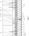
- connection area of two facade elements 1 arranged one above the other is shown as an example in the Figure 3
- the support plates 10 of the facade elements 1 have on their mutually facing side surfaces 11 the said means 12 for positive connection in the form of a groove 13 (upper facade element 1) and a tongue 14 (lower facade element 1).
- the upper facade element 1 is aligned and held by the lower facade element 1.
- the facade elements 1 are each placed at a distance x from the building substrate 3, so that an air layer 90 is formed. Unevenness in the substrate 3 can be absorbed via the air layer 90.
- the air layer 90 is designed as a standing air layer for reasons of thermal insulation.
- insulating strips 4 are inserted between the building substrate 3 and the facade elements 1.
- the thermal insulation layers 20 have a profile 40 along at least one side edge 21, which is formed by a surface 22 facing the reinforcement layer 30 and a side surface 23 of the thermal insulation layer 20 (see Figure 3 ).
- the profile 40 also serves as a connection or plastering strip for the reinforcement layer 30.
- the profile 40 is L-shaped for this purpose.
- the profile 40 of the upper facade element 1, which is arranged along a lower side edge 21, additionally has a drip edge 41.
- the facade elements 1 in the present case have a further profile 40 (see Figure 1 ) and/or a fabric angle 50 (see Figure 3 ). Both the profile 40 and the fabric angle 50 form a defined support surface for the insulation strip 5.
- FIGS. 4a) and 4b ) show the connection area of the support plates 10 of two adjacent facade elements 1, without the further Layers, that is, without thermal insulation layer 20, reinforcement layer 30 and cover layer 80.
- the carrier plates 10 have means 12 for positive connection on their side surfaces 11, which are designed as a groove 13 and tongue 14.
- the tongue 14 is formed by a strip with a trapezoidal cross-section that is inserted, preferably pressed, into a groove 13 in the left support plate 10. At the other end, the tongue 14 engages in an oppositely formed groove 13 in the right support plate 10.
- the facade elements can be installed in a tilted position and then brought into their final installation position by pivoting. This is particularly advantageous when the facade elements 1 are particularly large, for example, storey high.
- the spring 14 is formed by a bar with a rectangular cross-section.
- the bar is in turn inserted or pressed into a groove 13 of the left support plate 10.
- the spring 14 engages in a groove 13 of the right support plate 10, which also has a rectangular cross-section.
Landscapes
- Engineering & Computer Science (AREA)
- Architecture (AREA)
- Civil Engineering (AREA)
- Structural Engineering (AREA)
- Finishing Walls (AREA)
Applications Claiming Priority (1)
| Application Number | Priority Date | Filing Date | Title |
|---|---|---|---|
| DE102023002937.8A DE102023002937A1 (de) | 2023-07-18 | 2023-07-18 | Vorgefertigtes Fassadenelement, Fassadensystem sowie Verfahren zur Herstellung einer gedämmten Fassade |
Publications (1)
| Publication Number | Publication Date |
|---|---|
| EP4495351A1 true EP4495351A1 (fr) | 2025-01-22 |
Family
ID=91585427
Family Applications (1)
| Application Number | Title | Priority Date | Filing Date |
|---|---|---|---|
| EP24182758.3A Pending EP4495351A1 (fr) | 2023-07-18 | 2024-06-18 | Élément de façade préfabriqué, système de façade ainsi que procédé de fabrication d'une façade isolée |
Country Status (2)
| Country | Link |
|---|---|
| EP (1) | EP4495351A1 (fr) |
| DE (1) | DE102023002937A1 (fr) |
Citations (4)
| Publication number | Priority date | Publication date | Assignee | Title |
|---|---|---|---|---|
| DE2719448A1 (de) * | 1977-04-30 | 1978-11-02 | Toos | Verkleidungsplatte |
| FR2961833A1 (fr) * | 2010-06-29 | 2011-12-30 | Brique Iso | Panneau d'isolation thermique |
| CN110397240A (zh) * | 2019-07-31 | 2019-11-01 | 湖北卓宝建筑节能科技有限公司 | 一种保温板 |
| CN115405017A (zh) * | 2022-09-06 | 2022-11-29 | 郑州工大高新材料科技有限公司 | 一种建筑外墙无机保温装饰一体化墙及其施工方法 |
-
2023
- 2023-07-18 DE DE102023002937.8A patent/DE102023002937A1/de active Pending
-
2024
- 2024-06-18 EP EP24182758.3A patent/EP4495351A1/fr active Pending
Patent Citations (4)
| Publication number | Priority date | Publication date | Assignee | Title |
|---|---|---|---|---|
| DE2719448A1 (de) * | 1977-04-30 | 1978-11-02 | Toos | Verkleidungsplatte |
| FR2961833A1 (fr) * | 2010-06-29 | 2011-12-30 | Brique Iso | Panneau d'isolation thermique |
| CN110397240A (zh) * | 2019-07-31 | 2019-11-01 | 湖北卓宝建筑节能科技有限公司 | 一种保温板 |
| CN115405017A (zh) * | 2022-09-06 | 2022-11-29 | 郑州工大高新材料科技有限公司 | 一种建筑外墙无机保温装饰一体化墙及其施工方法 |
Also Published As
| Publication number | Publication date |
|---|---|
| DE102023002937A1 (de) | 2025-01-23 |
Similar Documents
| Publication | Publication Date | Title |
|---|---|---|
| EP3504386B1 (fr) | Maison modulaire | |
| DE69503182T2 (de) | Dachunterkonstruktion für mit Dacheindeckungsplatten gedeckte Dächer und Verfahren zur Herstellung der Dachunterkonstruktion | |
| EP4368792B1 (fr) | Procédé de rénovation énergétique de bâtiments | |
| EP3543416B1 (fr) | Élément de plafond bois-béton | |
| DE19704112C2 (de) | Wärmedämmende Fassadenverkleidung | |
| EP0795659A1 (fr) | Construction de toit | |
| EP3792424A1 (fr) | Élément de revêtement de toit et de paroi, système de revêtement de toit et de paroi, en particulier système de revêtement de toit et de paroi ventilé par l'arrière ou pouvant être ventilé par l'arrière et paroi, ainsi que paroi, en particulier paroi de cadre en bois, et toit | |
| AT527289B1 (de) | Bogenhaus | |
| EP4495351A1 (fr) | Élément de façade préfabriqué, système de façade ainsi que procédé de fabrication d'une façade isolée | |
| EP1045945B1 (fr) | Utilisation d'elements support pour fixer des substructures | |
| DE3425011A1 (de) | Fassadendaemmplatte | |
| DE102022103122A1 (de) | Dämmmodul für ein Gebäude | |
| DE9404632U1 (de) | Dachgaube | |
| AT398229B (de) | Schachteinrichtung mit einem nach unten offenen aufnahmeschacht zur aufnahme eines rolladens, einer jalousie oder dergleichen | |
| DE29615672U1 (de) | Großflächige Putzträgerplatte mit vorgefertigter Unterputzschicht für ein selbstbaufähiges Wärmedämmsystem | |
| EP4403716B1 (fr) | Elément de paroi pour l'isolation thermique d'une surface de paroi intérieure | |
| DE102016102780B4 (de) | Anordnung mit mindestens einem Dach- oder Fassadenelement in Gestalt eines sandwichartig aufgebauten Dämmpaneels und mit einem benachbart zu dem Dach- oder Fassadenelement angeordneten Fensterelement | |
| DE60121182T2 (de) | Selbsttragendes baulelement aus holz | |
| AT500597B1 (de) | Bauwerksmodul | |
| DE10006492A1 (de) | Haus mit Fertigbauelementen für den leicht handhabbaren Eigenbau | |
| DE3328092A1 (de) | Platte zur isolierung von daechern, boeden, wandflaechen oder dgl. | |
| DE102023116216A1 (de) | Dämmmodul für ein Gebäude | |
| DE19618587C2 (de) | Verfahren zum Errichten einer Unterkonstruktion und dafür geeignetes Dachausbauelement | |
| EP3067483B1 (fr) | Montage de mur pour un système de bâtiment, en particulier un immeuble d'habitation | |
| DE29703798U1 (de) | Achteckförmiges Gebäude in Holzbauweise |
Legal Events
| Date | Code | Title | Description |
|---|---|---|---|
| PUAI | Public reference made under article 153(3) epc to a published international application that has entered the european phase |
Free format text: ORIGINAL CODE: 0009012 |
|
| STAA | Information on the status of an ep patent application or granted ep patent |
Free format text: STATUS: THE APPLICATION HAS BEEN PUBLISHED |
|
| AK | Designated contracting states |
Kind code of ref document: A1 Designated state(s): AL AT BE BG CH CY CZ DE DK EE ES FI FR GB GR HR HU IE IS IT LI LT LU LV MC ME MK MT NL NO PL PT RO RS SE SI SK SM TR |
|
| STAA | Information on the status of an ep patent application or granted ep patent |
Free format text: STATUS: REQUEST FOR EXAMINATION WAS MADE |
|
| 17P | Request for examination filed |
Effective date: 20250625 |