EP4495352A1 - Carreau personnalisable pour système de plate-forme modulaire, système de plate-forme modulaire avec carreau personnalisable, et procédé de fabrication de plate-forme - Google Patents
Carreau personnalisable pour système de plate-forme modulaire, système de plate-forme modulaire avec carreau personnalisable, et procédé de fabrication de plate-forme Download PDFInfo
- Publication number
- EP4495352A1 EP4495352A1 EP24188337.0A EP24188337A EP4495352A1 EP 4495352 A1 EP4495352 A1 EP 4495352A1 EP 24188337 A EP24188337 A EP 24188337A EP 4495352 A1 EP4495352 A1 EP 4495352A1
- Authority
- EP
- European Patent Office
- Prior art keywords
- tile
- channels
- beams
- cutting
- platform system
- Prior art date
- Legal status (The legal status is an assumption and is not a legal conclusion. Google has not performed a legal analysis and makes no representation as to the accuracy of the status listed.)
- Pending
Links
- 238000000034 method Methods 0.000 title claims description 7
- 230000002093 peripheral effect Effects 0.000 claims description 24
- 239000000463 material Substances 0.000 claims description 17
- 230000006872 improvement Effects 0.000 claims description 3
- 238000004513 sizing Methods 0.000 abstract description 10
- 229920000642 polymer Polymers 0.000 description 7
- 229910052782 aluminium Inorganic materials 0.000 description 6
- XAGFODPZIPBFFR-UHFFFAOYSA-N aluminium Chemical compound [Al] XAGFODPZIPBFFR-UHFFFAOYSA-N 0.000 description 6
- 239000007769 metal material Substances 0.000 description 5
- 238000010276 construction Methods 0.000 description 4
- -1 polypropylene Polymers 0.000 description 4
- 230000015572 biosynthetic process Effects 0.000 description 3
- 229910052751 metal Inorganic materials 0.000 description 3
- 239000002184 metal Substances 0.000 description 3
- 239000007787 solid Substances 0.000 description 3
- 229910000838 Al alloy Inorganic materials 0.000 description 2
- 239000004743 Polypropylene Substances 0.000 description 2
- 230000009471 action Effects 0.000 description 2
- 230000008901 benefit Effects 0.000 description 2
- 229920001903 high density polyethylene Polymers 0.000 description 2
- 239000004700 high-density polyethylene Substances 0.000 description 2
- 229920001155 polypropylene Polymers 0.000 description 2
- 238000005096 rolling process Methods 0.000 description 2
- 239000004698 Polyethylene Substances 0.000 description 1
- 229910045601 alloy Inorganic materials 0.000 description 1
- 239000000956 alloy Substances 0.000 description 1
- 230000004075 alteration Effects 0.000 description 1
- 230000004888 barrier function Effects 0.000 description 1
- 230000008859 change Effects 0.000 description 1
- 239000002131 composite material Substances 0.000 description 1
- 230000001419 dependent effect Effects 0.000 description 1
- 238000009434 installation Methods 0.000 description 1
- 150000002739 metals Chemical class 0.000 description 1
- 230000004048 modification Effects 0.000 description 1
- 238000012986 modification Methods 0.000 description 1
- 239000004033 plastic Substances 0.000 description 1
- 229920003023 plastic Polymers 0.000 description 1
- 229920000573 polyethylene Polymers 0.000 description 1
- 239000002861 polymer material Substances 0.000 description 1
- 229920000915 polyvinyl chloride Polymers 0.000 description 1
- 239000004800 polyvinyl chloride Substances 0.000 description 1
- 230000003362 replicative effect Effects 0.000 description 1
- XLYOFNOQVPJJNP-UHFFFAOYSA-N water Substances O XLYOFNOQVPJJNP-UHFFFAOYSA-N 0.000 description 1
Images







Classifications
-
- E—FIXED CONSTRUCTIONS
- E04—BUILDING
- E04F—FINISHING WORK ON BUILDINGS, e.g. STAIRS, FLOORS
- E04F15/00—Flooring
- E04F15/02—Flooring or floor layers composed of a number of similar elements
- E04F15/024—Sectional false floors, e.g. computer floors
- E04F15/02405—Floor panels
-
- E—FIXED CONSTRUCTIONS
- E04—BUILDING
- E04F—FINISHING WORK ON BUILDINGS, e.g. STAIRS, FLOORS
- E04F15/00—Flooring
- E04F15/02—Flooring or floor layers composed of a number of similar elements
- E04F15/02172—Floor elements with an anti-skid main surface, other than with grooves
-
- E—FIXED CONSTRUCTIONS
- E04—BUILDING
- E04F—FINISHING WORK ON BUILDINGS, e.g. STAIRS, FLOORS
- E04F15/00—Flooring
- E04F15/02—Flooring or floor layers composed of a number of similar elements
- E04F15/024—Sectional false floors, e.g. computer floors
- E04F15/02447—Supporting structures
- E04F15/02452—Details of junctions between the supporting structures and the panels or a panel-supporting framework
-
- E—FIXED CONSTRUCTIONS
- E04—BUILDING
- E04F—FINISHING WORK ON BUILDINGS, e.g. STAIRS, FLOORS
- E04F15/00—Flooring
- E04F15/02—Flooring or floor layers composed of a number of similar elements
- E04F15/024—Sectional false floors, e.g. computer floors
- E04F15/02447—Supporting structures
- E04F15/02458—Framework supporting the panels
-
- E—FIXED CONSTRUCTIONS
- E04—BUILDING
- E04F—FINISHING WORK ON BUILDINGS, e.g. STAIRS, FLOORS
- E04F15/00—Flooring
- E04F15/02—Flooring or floor layers composed of a number of similar elements
- E04F15/10—Flooring or floor layers composed of a number of similar elements of other materials, e.g. fibrous or chipped materials, organic plastics, magnesite tiles, hardboard, or with a top layer of other materials
- E04F15/105—Flooring or floor layers composed of a number of similar elements of other materials, e.g. fibrous or chipped materials, organic plastics, magnesite tiles, hardboard, or with a top layer of other materials of organic plastics with or without reinforcements or filling materials
-
- E—FIXED CONSTRUCTIONS
- E04—BUILDING
- E04F—FINISHING WORK ON BUILDINGS, e.g. STAIRS, FLOORS
- E04F15/00—Flooring
- E04F15/02—Flooring or floor layers composed of a number of similar elements
- E04F15/02044—Separate elements for fastening to an underlayer
- E04F2015/0205—Separate elements for fastening to an underlayer with load-supporting elongated furring elements between the flooring elements and the underlayer
-
- E—FIXED CONSTRUCTIONS
- E04—BUILDING
- E04F—FINISHING WORK ON BUILDINGS, e.g. STAIRS, FLOORS
- E04F2201/00—Joining sheets or plates or panels
- E04F2201/01—Joining sheets, plates or panels with edges in abutting relationship
- E04F2201/0138—Joining sheets, plates or panels with edges in abutting relationship by moving the sheets, plates or panels perpendicular to the main plane
-
- E—FIXED CONSTRUCTIONS
- E04—BUILDING
- E04F—FINISHING WORK ON BUILDINGS, e.g. STAIRS, FLOORS
- E04F2201/00—Joining sheets or plates or panels
- E04F2201/04—Other details of tongues or grooves
- E04F2201/042—Other details of tongues or grooves with grooves positioned on the rear-side of the panel
Definitions
- a modular platform system that uses tiles, beams, and legs, each being configured together to allow creation of differently-configured platforms in a simple fashion, uses a customizable tile that allows for precise size adjustment of a platform area of the modular platform system.
- Patent Nos. 4,676,036 to Bessert , 6,256,952 to Fahy et al. , 4,901,490 to Zinniel , 4,561,232 to Gladden, Sr. et al. , 7,360,343 to Spransy et al , and 2,956,653 and 3,180,460 to Liskey Jr. are examples of such systems.
- these platform systems lack flexibility and ease in the ability to make differently-configured platforms using the same components.
- these prior art systems are time consuming and inconvenient to create a desired platform, expensive, inflexible in accommodating different configurations, and are ad-hoc or special purpose in their design.
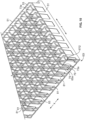
- FIG. 1 shows an example of this platform system. More particularly, Figure 1 shows a perspective view of one arrangement of the modular components of the modular platform system.
- the modular platform system (hereinafter the platform system) is designated by the reference numeral 10.
- the platform system has a number of components that are used to assemble a completed platform system, some essential components to create a functional platform and some optional components used if the platform application requires such optional components.
- the platform system 10 also includes brackets 7.
- the brackets 7 are configured to attach the legs 5 to the beams 3.
- the brackets 7 can also be used to secure a leg 5 to a ground surface if further securement of the platform system is required.
- Other means as would be known in the art can be used to secure the legs to the beams, e.g., a direct attachment of the leg to a beam without the need for the additional bracket.
- the beams 3 can be arranged to run in different directions for a given platform system.
- the platform system has one section 9, which uses four beams 3'and twelve tiles, with the beams 3' of section 9 running along direction "X".
- Another section of tiles 11 uses three beams 3 and eight tiles.
- the beams 3 in tile section 11 run along direction "Y", which is perpendicular to the direction "X" for beams 3' in tile section 9.
- the two sets of beams 3, 3' can be attached in one way using the brackets 7.
- the platform system 10 can also include cross beams 13.
- the cross beams 13 and legs 5 are configured so that one cross beam 13 can attach between adjacent legs 5. More particularly, the free end of tile section 11 has three legs 5 and two cross beams 13, each cross beam 13 arranged between adjacent legs 5. With the placement of the cross beams 13, the legs 5 are further stabilized against movement and shifting when the weight or other forces are applied to the platform.
- the cross beams are made of the same material as the beams and legs. However, since the cross beams do not see the loads that the beams and legs see, other materials for the cross beams can be employed, e.g., non-metallics like polymers.
- the hand railing can be configured to attach to the platform in any manner, and preferably to one or more legs, beams or other platform system components.
- the handrail 17 can be positioned with respect to the tile section 9 of tiles forming a floor of the platform system. While the railing 17 is shown associated with tile section 9, it can be associated with other sections of tiles or multiple railings could be used depending on the location of the platform assembly and need to the presence of a railing for safety purposes.
- the legs 5 can be made of the same material as the beams 3, 3' and also provided in a standard length, e.g., six feet. With this standard length, the legs can then be cut to length to provide a given platform system with tiles at different elevations. A six foot length of leg could provide six 1 foot sections for platform use, for example. Of course, the legs 5 could be supplied in lengths specified by a customer for a particular platform system as well.
- the beams 3 would be made in six foot lengths as shown in tile sections 9 and 11 and this six foot length would accommodate four tiles that are 18 inches square.
- the legs are shortened in length as are the beams 3, with the beams being roughly 54 inches to accommodate a run of three 18 inch on side tiles 1b.
- FIG. 1 An example of the one type of adjustable height feature of the legs is shown in the platform system 10 of Figure 1 .
- a number of tiles 1b, beams 3". smaller height legs 5', cross beams 13, and brackets 7 are employed to create a step designated by the reference numeral 19.
- the beams 3, 3' for tile sections 9 and 11 are one length (the equivalent of four tiles in length) and the beams 3" that form the step 19 are shorter in length (three tiles in length).
- the construction of the step 19 illustrates the flexibility of the platform system as the same beams and legs that are used for each tile section 9 and 11 can be used to create step 19; just that the beams and legs are cut and reduced in length to form the step 19.
- This length flexibility in both the legs and beams allows a wide variety of elevations for a platform system or within a platform system and a wide variety of the arrangement of the tiles for a given platform system.
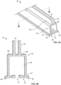
- the beam 3 has an elongate shape and a profiled cross section that provides a number of different functionalities for the assembly and stability of the platform system.
- Figure 4a shows a portion of the beam 3 in perspective view
- Figure 4b shows a sectional view of the beam 3.
- the beam 3 is one that is extruded from an aluminum alloy for ease of making the desired profile.
- Using aluminum as the material of the beam allows for the use of a high strength aluminum alloy such as from one from the 6000 series alloys.
- the tiles 1a and 1b are made of aluminum and are not easily customizable to precisely adjust the area of the platform for a desired use.
- the aluminum nature of the tiles make them difficult to cut to a desired size and there is really no easy way to resize the tile in an easy and efficient manner.
- One object of the invention is to provide an improved modular platform system, including one that uses a customizable size tile.
- Another object of the invention is to provide a customizable tile that can be used in existing platform systems.
- a further object of the invention is to provide the customizable tile with one or more support boards that can be used to support the tile once cut to a different size.
- the invention also provides an improved way to create the modular platform systems by allowing tile sizing to be done at the site of the platform system creation, thereby allowing changes in the platform size from that originally contemplated.
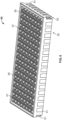
- the tile includes a top portion and a tile periphery, the tile periphery including peripheral members therearound.
- a tile size adjusting structure forms part of the tile, the tile size adjusting structure extending from an underside of the top portion.
- the tile size adjusting structure also has a periphery and the tile size adjusting structure periphery and the peripheral members form a peripheral slot inward of the peripheral members for tile attachment purposes.
- the tile size adjusting structure further includes a plurality of channels extending in first and second directions, and a plurality of cutting slots also extending in the first and second directions. The channels and cutting slots extending in the first direction intersecting with the channels and cutting slots extending in the second direction. For channels and cutting slots extending in the same direction, each channel is positioned between a pair of cutting slots, cutting along one or more of the cutting slots allowing the dimension of the tile to be reduced.
- tile can be made of any material that provides the necessary strength when used in a modular platform system
- a preferred material is a polymeric material as such materials are easier to cut than metals such as aluminum.
- each cutting slot is formed by one of the opposing discontinuous walls used for channel formation and a second discontinuous wall.
- the second discontinuous wall is formed by wall segments of the opposing discontinuous walls that form channels that intersect the cutting slot.
- the corners of the periphery of the tile size adjusting structure includes l-shaped wall segments, such l-shaped wall segments cooperating in forming the peripheral slots adjacent the peripheral members of the tile.
- the tile top portion can have virtually any configuration, including one with openings therethrough and one with a top surface that is closed and has no openings.
- the top surface of the tile, with openings or not, can include traction means as raised portions on the top surface or recesses therein to provide traction for movement by a user or objects on the top surface.
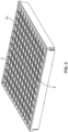
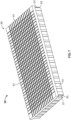
- FIG. 7 shows an alternative tile configuration to tile 50, designated as 50'.
- the tile 50' has a solid top portion 59 with intersecting slots 61 in the top portion 59 for traction purposes. While slots are shown, which are recessed portions in a top surface of the top portion, protrusions or raised portions can also be employed for traction purposes. Further, raised and recessed portions can be combined for traction purposes as well. These traction options could also apply to top surface portions of the tile 50 has openings therethrough.
- the channels are sized to accommodate members to provide support along the length or width of the tile once is customized in size.
- the channels can also function to attach to a beam of a platform system and this functionality is described in more detail below.
- both the channels and the cutting slots allows the tile to be cut in a number of different configurations for optimum flexibility in determining a final width and length of the tile when customized in size and still provide the needed support when used in a modular platform system.
- a pair of discontinuous walls 67a1 and 67a2 are provided.
- the walls are discontinuous as each wall must have a space for x-direction channels 65a-65g.
- the pair of discontinuous walls are designated by reference numerals 69a1 and 69a2.
- These x-direction discontinuous walls have the same longitudinal configuration as y-direction walls 67a1 and 67a2, just that they provide spaces for channels 63a-p.
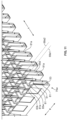
- the pins 79 and wall segments 81 are arranged on an underside of the tile 50 in an alignment, wherein spaced apart opposing pins 79 are arranged to form part of the channel 65a for example.
- a wall segment 81 and a pin 79 adjacent thereto not only form part of the discontinuous wall 67i2, they also form part of a cutting slot running in the x direction, cutting slot 73a for example.
- one of the pair of opposing discontinuous wall sections and faces of the wall segments 81 form the cutting slots.
- FIG 11 a view along the line Xi-XI of Figure 8 , shows cutting slot 75w. It can be seen that one wall of the cutting slot is formed by faces 81a of the wall segments 81 form a discontinuous wall 85w. This discontinuous wall 85w coupled with discontinuous wall section 6711, see Figure 9 , forms the cutting slot 75w.
- the discontinuous wall section 6711 and faces 81a of the wall segments 81 function as a guide for cutting of the tile along the cutting slot 75w.
- each corner of the tile underside structure has an l-shaped wall segment 84 made up of two wall segments joined together. There is no need to have disconnected wall segments at the corners of the underside tile structure as the cutting slots are spaced from each slot 53 that follows the periphery of the tile.
- the y direction channels 63a-p and x direction channels 65a-65g are designed with two functions in mind.
- the channels accommodate one or more support boards 90, which is shown in Figure 12 .
- the support board 90 is designed to press fit within one or more of the channels 63a-p and 65a-g in the tile 50 and rest on one of the supporting surfaces 39 of the beam shown in Figure 4B .
- the support board 90 provides support for the tile when it is sized is changed by removing parts of the tile using the cutting slots.
- Another function of the channels 63a-9 and 65a-g has the channels replicating the function of the outer peripheral member 51 and the slot 53 as described in more detail below.
- Figure 13 shows an uncut tile 50 in combination a pair of support boards 90.
- the support boards 90 are positioned in x-direction channels 65a and 65g.
- the tile is then cut along cutting slots 73a and 73n so that the tile would be reduced in with y direction while maintaining the same length in the x direction.
- the tile could then be used in a platform system with the y direction slots 53 engaging a pair of spaced apart beams.
- the support boards 90 are sized so that a face 93 of each end portion 91 would rest on the supporting surfaces 39 of the beam 3, see Figures 4A and 4B .
- the parts of the tile in terms of the outer peripheral member 51 and slot 53 are used in support of the tile with the beams 3.
- Figure 12 shows the tile dimension adjusted in the y direction
- the support boards 90 could be arranged in the two of the channels 63a-63p and the tile dimension could be adjusted in the x direction as well.
- the other set of original outer peripheral members 51 and slots 53 extending in the x-direction would be used to secure the tile to a pair of beams 3.
- Figure 14 shows another schematic similar to that use in Figure 9 as an example of the tile being reduced in both x and y directions.
- the tile is reduced in dimension in both the x and y directions.
- the tile would be cut at y-direction cutting slot 75o and x-direction cutting slot 73j.
- a support board 90 could be inserted into channel 65e.
- the tile could be placed between two beams, one beam engaging the channel 63h and the other beam engaging the y-direction slot 53.
- the tile is supported across its longer dimension.
- a support board could be placed in channel 63h and the x-direction slot 53 and the channel 65e could be used to engage beams of the platform system.
- a preferred material would be a non-metallic material, e.g., a polymer like polypropylene, polyethylene, polyvinyl chloride, and the like and engineered plastics like ABS and the like. Having a non-metallic material like a polymer makes it much easier to cut the tile to a desired size using the cutting slots as opposed to the aluminum tiles that were used in prior art systems.
- the support boards are also preferably made from a non-metallic material as well as the support boards may need to be cut to size.
- the boards extend along the entire x-direction of the tile so that cutting to narrow the width of the tile would not require cutting the support boards.
- the tile that is adjusted in width and length as shown in Figure 14 would require cutting of the support board.
- the support boards could be a metallic material, they could also be made from a polymeric material, like that exemplified for the tile itself.
- the tile when cut to a size that is quite small as compared to the original size of the tile for use in a modular platform system, the tile itself when attached to beams of the modular platform system may be able to support any loads placed on the tile during platform use. In these instances, one or more support boards would not be required.
- the customizable tile provides a significant advantage when construction platform systems like the one shown in Figure 1 .
- very fine size adjustments e.g., on the order of an inch can be achieved so that the platform can be easily sized for any designed configuration.
- the tiles are made of a polymer material, e.g., high density polyethylene, polypropylene, or other high strength polymers, they can be cut on site once the platform system is being constructed. They are also more easily cut than the prior art tiles, which were made of aluminum. With these tiles, it was typical to have to receive the dimensions of the platform system prior to delivery of the system and have the tiles cut prior to delivery. This pre-cutting did not provide any leeway if the dimensions of the platform system needed to be altered. With the customizable tiles, any dimensional changes could be easily accommodated on site when the platform system is being constructed.
- the cutting of the tile along the cutting slots can be done using any known cutting tool, saws, slitting blades, etc.
- the presence of the channels and capability to use a support board also the use of non-metallic materials as the support board can provided the needed strength to support a load on the tile when the tile is spanning beams in the platform system.
Landscapes
- Engineering & Computer Science (AREA)
- Architecture (AREA)
- Civil Engineering (AREA)
- Structural Engineering (AREA)
- General Engineering & Computer Science (AREA)
- Processing Of Stones Or Stones Resemblance Materials (AREA)
- Finishing Walls (AREA)
Applications Claiming Priority (1)
| Application Number | Priority Date | Filing Date | Title |
|---|---|---|---|
| US18/223,142 US20250027325A1 (en) | 2023-07-18 | 2023-07-18 | Customizable tile for modular platform system, modular platform system with customizable tile, and method of platform making |
Publications (1)
| Publication Number | Publication Date |
|---|---|
| EP4495352A1 true EP4495352A1 (fr) | 2025-01-22 |
Family
ID=91946733
Family Applications (1)
| Application Number | Title | Priority Date | Filing Date |
|---|---|---|---|
| EP24188337.0A Pending EP4495352A1 (fr) | 2023-07-18 | 2024-07-12 | Carreau personnalisable pour système de plate-forme modulaire, système de plate-forme modulaire avec carreau personnalisable, et procédé de fabrication de plate-forme |
Country Status (4)
| Country | Link |
|---|---|
| US (1) | US20250027325A1 (fr) |
| EP (1) | EP4495352A1 (fr) |
| CA (1) | CA3246461A1 (fr) |
| MX (1) | MX2024008892A (fr) |
Citations (9)
| Publication number | Priority date | Publication date | Assignee | Title |
|---|---|---|---|---|
| US2956653A (en) | 1958-11-14 | 1960-10-18 | Liskey Aluminum | Elevated false floor |
| US3180460A (en) | 1960-09-16 | 1965-04-27 | Liskey Aluminum | Floor panel for elevated flooring |
| US4561232A (en) | 1982-08-26 | 1985-12-31 | Tate Architectural Products, Inc. | Modular tile with positioning means for use with an access floor panel system |
| US4676036A (en) | 1985-05-01 | 1987-06-30 | Airtite, Inc. | Integrated raised flooring system |
| US4901490A (en) | 1984-12-17 | 1990-02-20 | Gabalan Corporation | Raised flooring panel and raised flooring assemblies |
| US6256952B1 (en) | 1998-07-27 | 2001-07-10 | Interface, Inc. | Perforated raised flooring panel |
| US20050252109A1 (en) * | 2004-02-20 | 2005-11-17 | Fuccella Daniel C | Interlocking modular floor tile |
| US7360343B1 (en) | 2002-05-07 | 2008-04-22 | Daw Technologies, Inc. | Raised access floor |
| US20220064965A1 (en) * | 2020-09-03 | 2022-03-03 | Wearwell, Llc | Modular platform system and method of assembly |
-
2023
- 2023-07-18 US US18/223,142 patent/US20250027325A1/en not_active Abandoned
-
2024
- 2024-07-11 CA CA3246461A patent/CA3246461A1/fr active Pending
- 2024-07-12 EP EP24188337.0A patent/EP4495352A1/fr active Pending
- 2024-07-17 MX MX2024008892A patent/MX2024008892A/es unknown
Patent Citations (9)
| Publication number | Priority date | Publication date | Assignee | Title |
|---|---|---|---|---|
| US2956653A (en) | 1958-11-14 | 1960-10-18 | Liskey Aluminum | Elevated false floor |
| US3180460A (en) | 1960-09-16 | 1965-04-27 | Liskey Aluminum | Floor panel for elevated flooring |
| US4561232A (en) | 1982-08-26 | 1985-12-31 | Tate Architectural Products, Inc. | Modular tile with positioning means for use with an access floor panel system |
| US4901490A (en) | 1984-12-17 | 1990-02-20 | Gabalan Corporation | Raised flooring panel and raised flooring assemblies |
| US4676036A (en) | 1985-05-01 | 1987-06-30 | Airtite, Inc. | Integrated raised flooring system |
| US6256952B1 (en) | 1998-07-27 | 2001-07-10 | Interface, Inc. | Perforated raised flooring panel |
| US7360343B1 (en) | 2002-05-07 | 2008-04-22 | Daw Technologies, Inc. | Raised access floor |
| US20050252109A1 (en) * | 2004-02-20 | 2005-11-17 | Fuccella Daniel C | Interlocking modular floor tile |
| US20220064965A1 (en) * | 2020-09-03 | 2022-03-03 | Wearwell, Llc | Modular platform system and method of assembly |
Also Published As
| Publication number | Publication date |
|---|---|
| US20250027325A1 (en) | 2025-01-23 |
| CA3246461A1 (fr) | 2025-06-09 |
| MX2024008892A (es) | 2025-02-10 |
Similar Documents
| Publication | Publication Date | Title |
|---|---|---|
| EP2549029B1 (fr) | Système de plate-forme | |
| DE602005004148T2 (de) | Abziehbalken | |
| EP1211365B1 (fr) | Système de plancher | |
| EP3964671B1 (fr) | Système de plate-forme modulaire et procédé d'assemblage | |
| US20150034421A1 (en) | Scaffold Deck System With A Float Bar Support For Creating An Opening To Accommodate Obstacles | |
| US20090188183A1 (en) | Stair system with adjustable width | |
| EP4495352A1 (fr) | Carreau personnalisable pour système de plate-forme modulaire, système de plate-forme modulaire avec carreau personnalisable, et procédé de fabrication de plate-forme | |
| EP0752038A1 (fr) | Planche de placage | |
| EP1840297A2 (fr) | Insert de couverture | |
| AU2008306221B2 (en) | Modular element for making fixed ladders | |
| WO2007002605A2 (fr) | Système d’escalier avec centre extensible | |
| WO2018200849A1 (fr) | Madriers d'échafaudage améliorés | |
| GB2377248A (en) | Toe board support | |
| AU2023362003A1 (en) | Safety device for ceiling formwork | |
| US6112854A (en) | Toe board for scaffolding | |
| EP3553251B1 (fr) | Ensemble ainsi qu'une structure de support et un profilé pour un tel ensemble | |
| EP0409029B1 (fr) | Profilé pour le support de panneaux de plafond | |
| EP3321421B1 (fr) | Drain à fente | |
| EP3315693B1 (fr) | Barrière de sécurité | |
| US12546104B2 (en) | Modular balcony system, components thereof and method of assembly and installation thereof | |
| EP4202177B1 (fr) | Échelle | |
| JP7710960B2 (ja) | パネル体切断補助治具 | |
| GB2499186A (en) | Board connector system for platforms | |
| KR20090006429U (ko) | 절토부 점검용 발판 | |
| AU8935001A (en) | Concrete floors |
Legal Events
| Date | Code | Title | Description |
|---|---|---|---|
| PUAI | Public reference made under article 153(3) epc to a published international application that has entered the european phase |
Free format text: ORIGINAL CODE: 0009012 |
|
| STAA | Information on the status of an ep patent application or granted ep patent |
Free format text: STATUS: THE APPLICATION HAS BEEN PUBLISHED |
|
| AK | Designated contracting states |
Kind code of ref document: A1 Designated state(s): AL AT BE BG CH CY CZ DE DK EE ES FI FR GB GR HR HU IE IS IT LI LT LU LV MC ME MK MT NL NO PL PT RO RS SE SI SK SM TR |
|
| STAA | Information on the status of an ep patent application or granted ep patent |
Free format text: STATUS: REQUEST FOR EXAMINATION WAS MADE |
|
| 17P | Request for examination filed |
Effective date: 20250303 |