EP4495400A1 - Appareil de soupape à orifices multiples et système de gestion thermique l'utilisant - Google Patents
Appareil de soupape à orifices multiples et système de gestion thermique l'utilisant Download PDFInfo
- Publication number
- EP4495400A1 EP4495400A1 EP22932394.4A EP22932394A EP4495400A1 EP 4495400 A1 EP4495400 A1 EP 4495400A1 EP 22932394 A EP22932394 A EP 22932394A EP 4495400 A1 EP4495400 A1 EP 4495400A1
- Authority
- EP
- European Patent Office
- Prior art keywords
- valve
- gear
- portholes
- port
- housing
- Prior art date
- Legal status (The legal status is an assumption and is not a legal conclusion. Google has not performed a legal analysis and makes no representation as to the accuracy of the status listed.)
- Pending
Links
Images








Classifications
-
- F—MECHANICAL ENGINEERING; LIGHTING; HEATING; WEAPONS; BLASTING
- F16—ENGINEERING ELEMENTS AND UNITS; GENERAL MEASURES FOR PRODUCING AND MAINTAINING EFFECTIVE FUNCTIONING OF MACHINES OR INSTALLATIONS; THERMAL INSULATION IN GENERAL
- F16K—VALVES; TAPS; COCKS; ACTUATING-FLOATS; DEVICES FOR VENTING OR AERATING
- F16K11/00—Multiple-way valves, e.g. mixing valves; Pipe fittings incorporating such valves
- F16K11/10—Multiple-way valves, e.g. mixing valves; Pipe fittings incorporating such valves with two or more closure members not moving as a unit
- F16K11/14—Multiple-way valves, e.g. mixing valves; Pipe fittings incorporating such valves with two or more closure members not moving as a unit operated by one actuating member, e.g. a handle
- F16K11/16—Multiple-way valves, e.g. mixing valves; Pipe fittings incorporating such valves with two or more closure members not moving as a unit operated by one actuating member, e.g. a handle which only slides, or only turns, or only swings in one plane
- F16K11/163—Multiple-way valves, e.g. mixing valves; Pipe fittings incorporating such valves with two or more closure members not moving as a unit operated by one actuating member, e.g. a handle which only slides, or only turns, or only swings in one plane only turns
- F16K11/165—Multiple-way valves, e.g. mixing valves; Pipe fittings incorporating such valves with two or more closure members not moving as a unit operated by one actuating member, e.g. a handle which only slides, or only turns, or only swings in one plane only turns with the rotating spindles parallel to the closure members
-
- F—MECHANICAL ENGINEERING; LIGHTING; HEATING; WEAPONS; BLASTING
- F01—MACHINES OR ENGINES IN GENERAL; ENGINE PLANTS IN GENERAL; STEAM ENGINES
- F01P—COOLING OF MACHINES OR ENGINES IN GENERAL; COOLING OF INTERNAL-COMBUSTION ENGINES
- F01P7/00—Controlling of coolant flow
- F01P7/14—Controlling of coolant flow the coolant being liquid
- F01P7/16—Controlling of coolant flow the coolant being liquid by thermostatic control
- F01P7/165—Controlling of coolant flow the coolant being liquid by thermostatic control characterised by systems with two or more loops
-
- F—MECHANICAL ENGINEERING; LIGHTING; HEATING; WEAPONS; BLASTING
- F16—ENGINEERING ELEMENTS AND UNITS; GENERAL MEASURES FOR PRODUCING AND MAINTAINING EFFECTIVE FUNCTIONING OF MACHINES OR INSTALLATIONS; THERMAL INSULATION IN GENERAL
- F16K—VALVES; TAPS; COCKS; ACTUATING-FLOATS; DEVICES FOR VENTING OR AERATING
- F16K11/00—Multiple-way valves, e.g. mixing valves; Pipe fittings incorporating such valves
- F16K11/02—Multiple-way valves, e.g. mixing valves; Pipe fittings incorporating such valves with all movable sealing faces moving as one unit
- F16K11/08—Multiple-way valves, e.g. mixing valves; Pipe fittings incorporating such valves with all movable sealing faces moving as one unit comprising only taps or cocks
- F16K11/085—Multiple-way valves, e.g. mixing valves; Pipe fittings incorporating such valves with all movable sealing faces moving as one unit comprising only taps or cocks with cylindrical plug
- F16K11/0853—Multiple-way valves, e.g. mixing valves; Pipe fittings incorporating such valves with all movable sealing faces moving as one unit comprising only taps or cocks with cylindrical plug having all the connecting conduits situated in a single plane perpendicular to the axis of the plug
-
- F—MECHANICAL ENGINEERING; LIGHTING; HEATING; WEAPONS; BLASTING
- F16—ENGINEERING ELEMENTS AND UNITS; GENERAL MEASURES FOR PRODUCING AND MAINTAINING EFFECTIVE FUNCTIONING OF MACHINES OR INSTALLATIONS; THERMAL INSULATION IN GENERAL
- F16K—VALVES; TAPS; COCKS; ACTUATING-FLOATS; DEVICES FOR VENTING OR AERATING
- F16K11/00—Multiple-way valves, e.g. mixing valves; Pipe fittings incorporating such valves
- F16K11/02—Multiple-way valves, e.g. mixing valves; Pipe fittings incorporating such valves with all movable sealing faces moving as one unit
- F16K11/08—Multiple-way valves, e.g. mixing valves; Pipe fittings incorporating such valves with all movable sealing faces moving as one unit comprising only taps or cocks
- F16K11/085—Multiple-way valves, e.g. mixing valves; Pipe fittings incorporating such valves with all movable sealing faces moving as one unit comprising only taps or cocks with cylindrical plug
- F16K11/0856—Multiple-way valves, e.g. mixing valves; Pipe fittings incorporating such valves with all movable sealing faces moving as one unit comprising only taps or cocks with cylindrical plug having all the connecting conduits situated in more than one plane perpendicular to the axis of the plug
-
- F—MECHANICAL ENGINEERING; LIGHTING; HEATING; WEAPONS; BLASTING
- F16—ENGINEERING ELEMENTS AND UNITS; GENERAL MEASURES FOR PRODUCING AND MAINTAINING EFFECTIVE FUNCTIONING OF MACHINES OR INSTALLATIONS; THERMAL INSULATION IN GENERAL
- F16K—VALVES; TAPS; COCKS; ACTUATING-FLOATS; DEVICES FOR VENTING OR AERATING
- F16K27/00—Construction of housing; Use of materials therefor
- F16K27/06—Construction of housing; Use of materials therefor of taps or cocks
- F16K27/065—Construction of housing; Use of materials therefor of taps or cocks with cylindrical plugs
-
- F—MECHANICAL ENGINEERING; LIGHTING; HEATING; WEAPONS; BLASTING
- F16—ENGINEERING ELEMENTS AND UNITS; GENERAL MEASURES FOR PRODUCING AND MAINTAINING EFFECTIVE FUNCTIONING OF MACHINES OR INSTALLATIONS; THERMAL INSULATION IN GENERAL
- F16K—VALVES; TAPS; COCKS; ACTUATING-FLOATS; DEVICES FOR VENTING OR AERATING
- F16K31/00—Actuating devices; Operating means; Releasing devices
- F16K31/02—Actuating devices; Operating means; Releasing devices electric; magnetic
- F16K31/04—Actuating devices; Operating means; Releasing devices electric; magnetic using a motor
- F16K31/041—Actuating devices; Operating means; Releasing devices electric; magnetic using a motor for rotating valves
-
- F—MECHANICAL ENGINEERING; LIGHTING; HEATING; WEAPONS; BLASTING
- F16—ENGINEERING ELEMENTS AND UNITS; GENERAL MEASURES FOR PRODUCING AND MAINTAINING EFFECTIVE FUNCTIONING OF MACHINES OR INSTALLATIONS; THERMAL INSULATION IN GENERAL
- F16K—VALVES; TAPS; COCKS; ACTUATING-FLOATS; DEVICES FOR VENTING OR AERATING
- F16K31/00—Actuating devices; Operating means; Releasing devices
- F16K31/44—Mechanical actuating means
- F16K31/53—Mechanical actuating means with toothed gearing
- F16K31/535—Mechanical actuating means with toothed gearing for rotating valves
-
- F—MECHANICAL ENGINEERING; LIGHTING; HEATING; WEAPONS; BLASTING
- F16—ENGINEERING ELEMENTS AND UNITS; GENERAL MEASURES FOR PRODUCING AND MAINTAINING EFFECTIVE FUNCTIONING OF MACHINES OR INSTALLATIONS; THERMAL INSULATION IN GENERAL
- F16K—VALVES; TAPS; COCKS; ACTUATING-FLOATS; DEVICES FOR VENTING OR AERATING
- F16K35/00—Means to prevent accidental or unauthorised actuation
- F16K35/04—Means to prevent accidental or unauthorised actuation yieldingly resisting the actuation
-
- F—MECHANICAL ENGINEERING; LIGHTING; HEATING; WEAPONS; BLASTING
- F01—MACHINES OR ENGINES IN GENERAL; ENGINE PLANTS IN GENERAL; STEAM ENGINES
- F01P—COOLING OF MACHINES OR ENGINES IN GENERAL; COOLING OF INTERNAL-COMBUSTION ENGINES
- F01P7/00—Controlling of coolant flow
- F01P7/14—Controlling of coolant flow the coolant being liquid
- F01P2007/146—Controlling of coolant flow the coolant being liquid using valves
Definitions
- the present invention relates to a multi-port valve apparatus allowing coolant to selectively circulate through a plurality of coolant flow paths and a thermal management system using the same.
- Electric vehicles obtain their driving energy from electrical energy rather than from the combustion of fossil fuels, unlike traditional vehicles. Electric vehicles, which produce no exhaust gases and generate very little noise, were not widely adopted due to issues like heavy battery weight and long charging times, but their development has recently accelerated due to increasing pollution problems and the fossil fuel depletion.
- the cooling system employs a water pump to circulate coolant through the motor, associated electrical components, and a heat source, effectively safeguarding these heat-generating components from overheating.
- the present invention has been conceived to solve the above problems and it is an object of the present invention to provide a multi-port valve apparatus and a thermal management system using the same that are capable of improving the temperature management efficiency of the coolant by reducing the overall package size of the valves, selectively circulating coolant to a plurality of coolant flow paths through the valves with guaranteed functionality, and facilitating separate or mixed distribution of coolant depending on circumstances.
- a multi-port valve apparatus includes a housing including a plurality of flow paths through which a cooling medium circulates, and an interior including a valve space and a flow space, a first valve rotatably provided in the valve space of the housing and configured to selectively circulate the cooling medium through the plurality of flow paths and the flow space, a second valve rotatably provided in the valve space of the housing to be rotated in conjunction with the first valve and configured to selectively circulate the cooling medium through the plurality of flow paths and the slow space, and an actuator provided in the housing and connected to the first valve to control the positions of the first and second valves.
- the plurality of flow paths and the flow space may be arranged separately in the housing.
- the first valve may include a plurality of first portholes formed on the outer surface thereof, and the second valve includes a plurality of second portholes, one of the plurality of first portholes and second portholes matching with the flow space depending on the rotational positions of the first and second valves, the remaining portholes configured to match to different ports.
- the first valve and the second valve each may include four first portholes and four second portholes, and one of the first portholes and one of the second portholes are connected through the flow space, forming six ports with the first valve and the second valve.
- the first portholes of the first valve may be spaced at 90° intervals, the second portholes of the second valve are spaced at 90° intervals, and the actuator rotates the first valve by 90° increments, causing the first and second valves to be linked at a predetermined rotation angle and to rotate together by the rotation angle.
- the first valve and the second valve may be coaxially aligned, the first valve including a first gear formed on the outer surface thereof, the second valve including a second gear formed on the outer surface thereof, the first and second gears meshing together via a connecting gear.
- the connecting gear may be rotatably provided in the flow space of the housing.
- the first gear may be formed along a part of the outer surface of the first valve, and the second gear is entirely formed along the outer surface of the second valve, the first gear meshing with the connecting gear based on the first valve rotating within a predetermined angle range, causing the second gear to rotate together with the connecting gear.
- the first valve and the second valve may be formed with facing end portions that overlap in a rotatable manner.
- the first valve and the second valve may be arranged with the center axes thereof aligned horizontally, the first valve including a first gear formed along part of the outer surface thereof, the second valve including a second gear formed along part of the outer surface thereof to mesh with the first gear.
- the second valve may include a support protrusion extending from the outer surface thereof on both sides of the second gear, the support protrusion configured to contact with the outer surface of the first valve.
- the second valve while the first valve is rotating, may be configured not to rotate when the support protrusion contacts with the outer surface of the first valve, and may be configured to rotate by a predetermined angle based on the first gear meshing with the second gear while the first valve rotates within a predetermined angle range.
- the first valve and the second valve may be arranged to intersect each other and mesh together.
- the first valve and the second valve may be coaxially aligned, the first valve including a driving groove having a predetermined area on one end portion thereof facing the second valve, the second valve including a corresponding driving protrusion inserted into the driving groove on one end portion facing the first valve.
- the first valve may be formed with the driving groove extending from the center axis by a predetermined angle, the second valve, while the first valve is rotating, configured not to rotate when the driving protrusion moves within the driving groove and configured to rotate in conjunction with the first valve to cause the driving protrusion to contact and to be pushed by either side of the driving groove when the first valve rotates more than a predetermined angle.
- the second valve may include a position-fixing protrusion protruding on the outer surface thereof, and the housing includes an elastic support member contacting with the outer surface of the second valve or the position-fixing protrusion of the second valve depending on the rotational position of the second valve.
- a thermal management system including the multi-port valve apparatus includes a first coolant line configured to circulate a cooling medium to a first pump, a battery, and a first heat exchanger, and a second coolant line configured to circulate the cooling medium to a second pump, a power electronics module, a second heat exchanger, and a radiator, wherein the coolant from the first coolant line and the second coolant line is selectively shared through the multi-port valve apparatus to switch the flow direction of the cooling medium by the multi-port valve apparatus.
- the multi-port valve apparatus and thermal management system using the same, structured as described in above, are advantageous in terms of improving the temperature management efficiency of the coolant by reducing the overall package size of the valves, selectively circulating coolant to a plurality of coolant flow paths through the valves with guaranteed functionality, and facilitating separate or mixed distribution of coolant depending on circumstances.
- first and second can be used to describe various components without limiting the components. The terms are used only for distinguishing one component from another component.
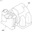
- FIG. 1 is a diagram illustrating a multi-port valve apparatus according to an embodiment of the present invention
- FIG. 2 is a side cross-sectional view of the multi-port valve apparatus of FIG. 1
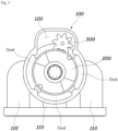
- FIG. 3 is a front cross-sectional view of the multi-port valve apparatus of FIG. 1
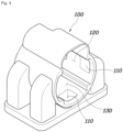
- FIG. 4 is a diagram illustrating a housing of the multi-port valve apparatus of FIG. 1
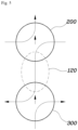
- FIG. 5 is a diagram illustrating the coolant circulation flow structure of the multi-port valve apparatus of FIG. 1 .
- FIG. 6 is a diagram illustrating the first and second valves according to the first embodiment
- FIGS. 7 to 10 are diagrams illustrating the operations of the first and second valves according to the first embodiment.
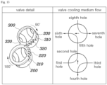
- FIGS. 11 to 14 are diagrams illustrating the operation of the first and second valves according to the second embodiment.
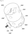
- FIG. 15 is a diagram illustrating the first and second valves according to the third embodiment.
- FIG. 16 is a diagram illustrating the first and second valves according to the fourth embodiment
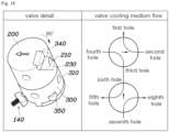
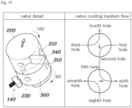
- FIGS. 17 to 20 are diagrams illustrating the operation of the first and second valves according to the fourth embodiment.
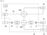
- FIG. 21 is a diagram illustrating a thermal management system according to the present invention.
- the multi-port valve apparatus includes a housing 100 with a plurality of flow paths 110 through which the cooling medium circulates, and an interior divided into a valve space 120 and a flow space 130, a first valve 200 rotatably installed in the valve space 120 of the housing 100 to selectively allow the cooling medium to flow through the plurality of flow paths 110 and the flow space 130, a second valve 300 rotatably installed in the valve space 120 of the housing 100 in linkage with the first valve 200 to selectively allow the cooling medium to flow through the plurality of flow paths 110 and the flow space 130, and an actuator 400 installed in the housing 100 and connected to the first valve 200 to control the rotational positions of the first and second valves 200 and 300.
- the multi-port valve apparatus includes a housing 100, a first valve 200, a second valve 300, and an actuator 400, wherein the actuator 400 rotates the first and second valves 200 and 300 to allow the cooling medium to circulate through the flow paths 110 and flow space 130 of the housing 100.
- the actuator 400 can be controlled by a controller, which may include a communication device for interacting with other controllers or sensors to manage its assigned functions, a memory for storing operating systems, logic instructions, and input/output information, and one or more processors for making the judgments, calculations, and decisions necessary for function control.
- This invention uniquely employs a single actuator 400 to control the rotational positions of the first and second valves 200 and 300, where the first value 200 is directly connected to the actuator 400 and the rotation of the first valve causes the second valve 300 to rotate in linkage with the first valve 200. Furthermore, the first valve 200 and the second valve 300 not only switch the flow direction of the cooling medium through the flow paths 110 in the housing 100 but also form a shared path for the cooling medium within the flow space 130 of the housing 130.
- the present invention determines the flow direction of the cooling medium by the first valve 200 and the second valve 300 provided inside the housing 100, and adjusts the position of the second valve 300 in conjunction with the first valve 200 using a single actuator 400. This allows for the overall package size of the valve apparatus to be reduced, enabling the cooling medium to flow through various paths.
- the housing 100 is configured with the plurality of flow paths 110 and the flow space 130 that are separately apart. This separation between the plurality of flow paths 110 and the flow space 130 prevents interference for each other and mixing of the cooling medium.
- the flow paths 110 within the housing 100 are arranged in a single direction, allowing for a reduced size of the housing 100 and ensuring sealing performance of each flow path 110.
- the shape of the gasket G that connects to the flow paths 110 of the housing 100 may be simplified.
- the first valve 200 has a plurality of first portholes 210 on the outer surface thereof
- the second valve 300 has a plurality of second portholes 310, the first portholes 210 and second portholes 310 being arranged such that one of them matches the flow space 130 depending on the rotational positions of the first valve 200 and second valve 300, while the remaining portholes are matched to different ports.
- first portholes 210 of the first valve 200 and the second portholes 310 of the second valve 300 are matched to either the flow paths 110 or the flow space 130 of the housing 100 depending on their rotational positions, allowing the cooling medium to be shared and circulated through the first valve 200 and second valve 300, or distributed through each flow path 110 to components requiring cooling.
- one of the first portholes 210 of the first valve 200 and the second portholes 310 of the second valve 300 is matched to the flow space 130, while the remaining first portholes 210 and second portholes 310 are matched to the flow paths 110 in the housing 100 to allow the cooling medium to be mixed and circulated or circulated individually for each component such that the cooling medium is distributed to the components requiring cooling.
- first valve 200 and the second valve 300 each have four first portholes 210 and four second portholes 310, and one of the first portholes 210 and one of the second portholes 310 are connected through the flow space 130, creating six ports with the first valve 200 and the second valve 300.
- the first portholes 210 of the first valve 200 and the second portholes 310 of the second valve 300 are spaced by 90° intervals, respectively, and the actuator 400 rotates the first valve 200 in 90° increments, ensuring synchronized rotation of the first valve 200 and the second valve 300 by the same angle from a predetermined rotation angle.
- the housing 100 forms six flow paths 110, allowing the cooling medium to circulate through the first valve 200 and the second valve 300 via a single flow space 130. That is, among the four first portholes 210 of the first valve 200 and the four second portholes 310 of the second valve 300, one of the first portholes 210 and one of the second portholes 310 are connected through a connecting passage depending on the rotational positions of the first valve 200 and the second valve 300, while the three remaining first portholes 210 and three remaining second portholes 310 are connected to components where the cooling medium circulates, thus forming a circulation circuit for the cooling medium.
- this present invention is configured such that the first valve 200 is connected to the actuator 400, and the second valve 300 is synchronized with the first valve 200, allowing the rotational positions of the first valve 200 and the second valve 300 to be changed by the operation of the actuator 400.
- the actuator 400 is configured to rotate the first valve 200 in 90° increments, altering the positions of the first portholes 210, and as the first valve 200 rotates within the predetermined rotation angle range of 90° to 180°, the second valve 300 rotates in synchronization with the first valve 200, causing the positions of the first portholes 210 and the second portholes 310 to change accordingly.
- the present invention may switch the flow direction of the cooling medium by altering the rotational positions of the first valve 200 and the second valve 300 using a single actuator 400. Further details on this aspect is provided below.
- valve structure according to the present invention can be applied in various embodiments as follows.
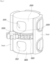
- first valve 200 and the second valve 300 are coaxially aligned as shown in FIG. 6 , with the first valve 200 having a first gear 220 formed on the outer surface thereof and the second valve 300 having a second gear 320 on the outer surface thereof, the first and second gears 220 and 320 meshing together via a connecting gear 500.
- the first valve 200 and the second valve 300 are arranged in the housing 100 to rotate around the same center axis, and the first gear 220 of the first valve 200, the second gear 320 of the second valve 300, and the connecting gear 500 are meshed with each other such that the rotation of the second valve 300 is linked to the rotation of the first valve 200.
- the first gear 220 of the first valve 200 and the second gear 320 of the second valve 300 are formed on the outer surfaces of their facing end portions to mesh with the connecting gear 500.
- the connecting gear 500 is rotatably installed in the flow space 130 of the housing 100, eliminating the need for separate space to accommodate the connecting gear 500 within the housing 100. Furthermore, even with the connecting gear 500 provided in the flow space 130 of the housing 100, the cooling medium may still circulate depending on the shape of the connecting gear 500. Additionally, the flow space 130 of the housing 100 can be formed larger than the connecting gear 500 to ensure a sufficient flow rate of the cooling medium.
- first valve 200 and the second valve 300 are formed that their respective facing end portions overlap in a rotatable manner. That is, as shown in FIGS. 2 and 6 , the first valve 200 and the second valve 300 are designed to form an insertion structure with their respective facing end portions in the direction facing each other, ensuring positional stability and independent rotation of the first valve 200 and the second valve 300. Additionally, as the first valve 200 and the second valve 300 are formed to overlap each other, the installation space for the first valve 200 and the second valve 300 is reduced, allowing the size of the housing 100 to be reduced.
- a first gear 220 is formed along a part of the outer surface of the first valve 200, and a second gear 320 is formed along the entire outer surface of the second valve 300, such that when the first valve 200 is rotated within a predetermined angle range, the first gear 220 engages with the connecting gear 500, causing the second valve 300 to rotate together with the connecting gear 500.
- the first valve 200 and the second valve 300 may have their respective portholes spaced at 90° intervals, and the first gear 220 of the first valve 200 may be designed to mesh with the connecting gear 500 after rotating 90° from its initial position and then rotate together to 180°. Accordingly, the predetermined angle range may be set from 90° to 180° such that when the first valve 200 rotates more than 90°, the first gear 220 meshes with the connecting gear 500, causing the connecting gear 500 to rotate, which in turn rotates the second valve 300.
- the actuator 400 may be operated to rotate the first valve 200 by 90° increments when changing the rotational positions of the first valve 200 and the second valve 300.
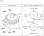
- the first portholes 210 of the first valve 200 may include first, second, third, and fourth holes interconnected, and the second portholes 310 of the second valve 300 may include fifth, sixth, seventh, and eighth holes.
- the fourth hole of the first valve 200 and the sixth hole of the second valve 300 are connected through the flow space 130 as shown in FIG. 7 .
- the actuator 400 when the actuator 400 operates to rotate the first valve 200 by 90°, the first valve 200 only rotates 90°, changing the positions of the first, second, third, and fourth holes of the first valve 200, and the second valve remains in position, which causes the third hole of the first valve 200 and the sixth hole of the second valve 300 to be connected through the flow space 130.
- the first valve 200 and the second valve 300 are arranged with their central axes horizontally aligned, and the first gear 220 is formed at a portion of the outer surface of the first valve 200, while the second gear 320 is formed at a portion of the outer surface of the second valve 300 to mesh with the first gear 220 of the first valve 200.
- first valve 200 and the second valve 300 are configured to arranged with their outer surfaces facing each other and their central axes horizontally aligned such that when the first gear 220 of the first valve 200 and the second gear 320 of the second valve 300 mesh with each other, the second valve 300 rotates in conjunction with the rotation of the first valve 200.
- first gear 220 of the first valve 200 and the second gear 320 of the second valve 300 are each formed in partial segments, when the first gear 220 and the second gear 320 do not mesh with each other, only the first valve 200 rotates, but when the first gear 220 and the second gear 320 do mesh with each other, the second valve 300 rotates in conjunction with the first valve 200.
- the second valve 300 has support protrusions 330 extending on both sides of the second gear 320 on its outer surface, and these support protrusions 330 are formed to contact with the outer surface of the first valve 200. These support protrusions 330 are formed in a manner that surrounds the outer surface of the first valve 200, creating a support structure for the first valve 200 and thereby preventing any unintended rotation of the second valve 300.
- the second valve 300 remains fixed in position, and when the first gear 220 of the first valve 200 meshes with the second gear 320 of the second valve 300, both the first valve 200 and the second valve 300 rotate together.
- the second valve 300 does not rotate when the support protrusions 330 remain in contact with the outer surface of the first valve 200, even though the first valve 200 rotates; however, when the first valve 200 rotates within a predetermined angle range and the first gear 220 meshes with the second gear 320, the second valve 300 rotates by a predetermined angle.
- the first valve 200 and the second valve 300 may have their respective portholes spaced at 90° intervals, and the first gear 220 of the first valve 200 may be designed to mesh with the second gear 320 after rotating 90° from its initial position and then rotate together to 180°. Accordingly, the predetermined angle range may be set from 90° to 180° such that when the first valve 200 rotates more than 90°, the first gear 220 meshes with the second gear 320, allowing both the first valve 200 and the second valve 300 to rotate together.
- the actuator 400 may be operated to rotate the first valve 200 by 90° increments when changing the rotational positions of the first valve 200 and the second valve 300.
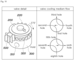
- the first portholes 210 of the first valve 200 may include first, second, third, and fourth holes interconnected, and the second portholes 310 of the second valve 300 may include fifth, sixth, seventh, and eighth holes.
- the fourth hole of the first valve 200 and the sixth hole of the second valve 300 are connected through the flow space 130 as shown in FIG. 11 .
- the actuator 400 when the actuator 400 operates to rotate the first valve 200 by 90°, the first valve 200 only rotates 90°, changing the positions of the first, second, third, and fourth holes of the first valve 200, and the second valve 300 remains in position, which causes the third hole of the first valve 200 and the sixth hole of the second valve 300 to be connected through the flow space 130.
- the first valve 200 and the second valve 300 may be arranged offset from each other such that their outer surfaces do not face each other, while still allowing the first gear 220 and the second gear 320 to mesh.
- This is shown as the third embodiment in FIG. 15 in which the first valve 200 and the second valve 300 are arranged offset from each other.
- the housing 100 may have a changeable shape to accommodate the integration of the first valve 200 and the second valve 300, and the flow space 130 within the housing 100 may be separately formed.
- the first valve 200 and the second valve 300 are coaxially aligned, with the first valve 200 having a driving groove 230 occupying a predetermined area on its end portion facing the second valve 300, and the second valve 300 having a corresponding driving protrusion 340 inserted into this groove 230 on its end portion facing the first valve 200.
- first valve 200 and the second valve 300 are coaxially arranged within the housing 100 to rotate around the same axis, and as the position of the driving groove 230 formed on the first valve 200 changes, the driving protrusion 340 on the second valve 300 moves, causing the second valve 300 to rotate in conjunction with the first valve 200.
- the first valve 200 and the second valve 300 create an overlapping structure through the insertion mechanism of the driving groove 230 and the driving protrusion 340, allowing the first valve 200 to rotate alone when its driving groove 230 shifts but the driving protrusion 300 remains in position during actuation by the actuator 400, whereas when either side of the driving groove 230 of the first valve 200 pushes the driving protrusion 340 of the second valve 300, both the first valve 200 and the second valve 300 rotate in linkage.
- the second valve 300 has a position-fixing protrusion 350 protruding on its outer surface
- the housing 100 is provided with an elastic support member 140 that contacts the outer surface of the second valve 300 or the position-fixing protrusion 350 of the second valve 300 depending on the rotational position of the second valve 300.
- the elastic support member 140 includes a spring 141 and a spacer 142, with the spring 141 installed in the housing 100 and the spacer 142 connected to the spring 141 formed to contact the outer surface of the second valve 300.
- the spacer 142 is shaped to contact the outer surface of the second valve 300 while encircling the position-fixing protrusion 350, ensuring smooth position regulation of the second valve 300 via the elastic support member 140.
- the second valve 300 may have a plurality of position-fixing protrusions 350 spaced along its outer surface.
- the position-fixing protrusions 350 may be spaced at intervals of 90°.
- the first valve 200 is designed with the driving groove 230 extending from the center axis by a certain angle, allowing the second valve 300, while the first valve 200 is rotating, to remain stationary when the driving protrusion 340 moves within the driving groove 230, but allowing the second valve 300 to rotate in conjunction with the first valve 200 when the first valve 200 rotates more than a predetermined angle, causing the driving protrusion 340 to contact and to be pushed by either side of the driving groove 230.
- the driving groove 230 of the firs valve 200 may be extended by 90° rotation range from the center axis, and the rotational movement of the second valve 300 is determined by the position of the driving protrusion 340 as the first valve 200 rotates.
- the driving protrusion 340 of the second valve 300 is pushed, causing both the first valve 200 and the second valve 300 to rotate together.
- the actuator 400 may be operated to rotate the first valve 200 by 90° increments when changing the rotational positions of the first valve 200 and the second valve 300.
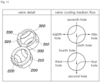
- the first portholes 210 of the first valve 200 may include first, second, third, and fourth holes interconnected, and the second portholes 310 of the second valve 300 may include fifth, sixth, seventh, and eighth holes.
- the fourth hole of the first valve 200 and the sixth hole of the second valve 300 are connected through the flow space 130 as shown in FIG. 17 .
- the actuator 400 operates to rotate the first valve 200 by 90°
- the first valve 200 only rotates, changing the positions of the first, second, third, and fourth holes of the first valve 200, and the second valve remains in position, which causes the third hole of the first valve 200 and the sixth hole of the second valve 300 to be connected through the flow space 130.
- the driving protrusion 340 of the second valve 300 shift contact from one side of the driving groove 230 and then the opposite side.
- the actuator 400 operates to rotate the first valve 200 an additional 90° within the set angle range, totaling 180°
- the first valve 200 pushes the driving protrusion 340 of the second valve 300, causing the second valve 300 to rotate 90° in linkage with the first valve 200.
- the positions of all the first, second, third, and fourth holes of the first valve 200 and the positions of all the fifth, sixth, seventh, and eighth holes of the second valve 300 are changed, which causes the second hole of the first valve 200 and the fifth hole of the second valve 300 to be connected through the flow space 130.
- the actuator 400 operates to rotate the first valve 200 back by 90°, the second valve 300 remains in position, and the third port of the first valve 200 and the fifth port of the second valve 300 are connected through the flow space 130.
- the driving protrusion 340 of the second valve 300 switches contact from the opposite side of the driving groove 230 to one side.
- the first valve 200 and the second valve 300 may be in a standby state for reverse operation to return to their original positions.
- the first valve 200 and the second valve 300 are configured for the actuator 400 to vary the rotational position of the first valve 200, thereby linking and rotating the second valve 300, and depending on the rotation angle of the first valve 200, the porthole positions of both valves 200 and 300 can change to switch the circulation direction of the cooling medium.
- the heat management system including the above described multi-port valve apparatus of the present invention may include a first coolant line 10 through which the cooling medium circulates to a first pump 11, a battery 12, and a first heat exchanger 13, and a second coolant line 20 through which the cooling medium circulates to a second pump 21, a power electronics module 22, a second heat exchanger 23, and a radiator 24, and may be configured for the coolant in the first coolant line 10 and second coolant line 20 to be selectively shared via the multi-port valve apparatus A, switching the circulation direction of the cooling medium.
- first coolant line 10 and the second coolant line 20 may each be provided with a reservoir RV.
- the cooling medium driven by the first pump 11, circulates and undergoes heat exchange through the first heat exchanger 13 and the battery 12.
- the first heat exchanger 13 may be configured to regulate the temperature of the coolant circulating in the first coolant line 10 through heat exchange with refrigerant, ambient air, or another cooling fluid.
- the cooling medium driven by the second pump 21, circulates and undergoes heat exchange through the radiator 24, the second heat exchanger 23, and the power electronics module 22.
- the second heat exchanger 23 may be configured to regulate the temperature of the coolant circulating in the second coolant line 20 by exchanging heat with refrigerant, ambient air, or another cooling fluid.
- the cooling of the battery 12 is achieved through heat exchange with coolant in the first coolant line 10
- the cooling of the power electronics module 22 is achieved through heat exchange with coolant in the second coolant line 20
- a heat pump may be implemented through heat exchange of the coolant via the first heat exchanger 13 and the second heat exchanger 23.
- the flow path of the coolant in the first coolant line 10 and the second coolant line 20 is determined by the first valve 200 and the second valve 300 housed within the housing 100.
- the housing 100, reservoir RV, first heat exchanger 13, and second heat exchanger 23 may be modularized.
- the flow path of the coolant in the first coolant line 10 and the second coolant line 20 is determined based on the rotational positions of the first valve 200 and the second valve 300, allowing the coolant to circulate individually in each coolant line or in a maxed manner across both coolant lines.
- This configuration allows the present invention to regulate the coolant temperature based on various conditions, such as indoor air conditioning, cooling the battery 12, cooling the power electronics module 22, and ambient temperature, thereby ensuring cooling efficiency through the coolant.
- the multi-port valve apparatus and thermal management system using the same, structured as described, are advantageous in terms of improving the temperature management efficiency of the coolant by reducing the overall package size of the valves, selectively circulating the coolant to a plurality of coolant flow paths through the valves with guaranteed functionality, and facilitating separate or mixed distribution of the coolant depending on circumstances.
Landscapes
- Engineering & Computer Science (AREA)
- General Engineering & Computer Science (AREA)
- Mechanical Engineering (AREA)
- Chemical & Material Sciences (AREA)
- Combustion & Propulsion (AREA)
- Multiple-Way Valves (AREA)
Applications Claiming Priority (2)
| Application Number | Priority Date | Filing Date | Title |
|---|---|---|---|
| KR1020220032277A KR102429374B1 (ko) | 2022-03-15 | 2022-03-15 | 다중 포트 밸브 장치 및 이를 이용한 열관리 시스템 |
| PCT/KR2022/010911 WO2023177027A1 (fr) | 2022-03-15 | 2022-07-25 | Appareil de soupape à orifices multiples et système de gestion thermique l'utilisant |
Publications (2)
| Publication Number | Publication Date |
|---|---|
| EP4495400A1 true EP4495400A1 (fr) | 2025-01-22 |
| EP4495400A4 EP4495400A4 (fr) | 2026-03-04 |
Family
ID=82837188
Family Applications (1)
| Application Number | Title | Priority Date | Filing Date |
|---|---|---|---|
| EP22932394.4A Pending EP4495400A4 (fr) | 2022-03-15 | 2022-07-25 | Appareil de soupape à orifices multiples et système de gestion thermique l'utilisant |
Country Status (4)
| Country | Link |
|---|---|
| US (1) | US20250215983A1 (fr) |
| EP (1) | EP4495400A4 (fr) |
| KR (1) | KR102429374B1 (fr) |
| WO (1) | WO2023177027A1 (fr) |
Families Citing this family (2)
| Publication number | Priority date | Publication date | Assignee | Title |
|---|---|---|---|---|
| KR102564037B1 (ko) | 2022-10-19 | 2023-08-07 | 디와이오토 주식회사 | 다중 유로가 구비된 밸브 장치 |
| KR102684766B1 (ko) * | 2023-01-04 | 2024-07-11 | 현대위아 주식회사 | 냉각매체 유통 장치 |
Family Cites Families (12)
| Publication number | Priority date | Publication date | Assignee | Title |
|---|---|---|---|---|
| JP6003716B2 (ja) * | 2012-04-17 | 2016-10-05 | 株式会社デンソー | 流路切替装置 |
| US9382833B2 (en) * | 2013-07-25 | 2016-07-05 | Schaeffler Technologies AG & Co. KG | Actuation system for multi-chamber thermal management valve module |
| JP6065779B2 (ja) * | 2013-07-31 | 2017-01-25 | 株式会社デンソー | 車両用熱管理システム |
| DE102015210157B4 (de) * | 2014-06-04 | 2021-12-23 | Schaeffler Technologies AG & Co. KG | Mehrkammer-Drehventilmodul für Wärme-Management |
| KR101683530B1 (ko) * | 2015-11-18 | 2016-12-07 | 현대자동차 주식회사 | 냉각수 제어밸브를 갖는 엔진시스템 |
| JP7405599B2 (ja) | 2018-12-25 | 2023-12-26 | Ntn株式会社 | 流量制御バルブ用シールおよび流量制御バルブ装置 |
| US10808863B2 (en) * | 2019-02-05 | 2020-10-20 | Schaeffler Technologies AG & Co. KG | Valve arrangement |
| KR102276255B1 (ko) * | 2019-11-11 | 2021-07-12 | 현대위아(주) | 차량 통합 열관리 멀티포트 밸브 |
| US11598441B2 (en) * | 2019-12-03 | 2023-03-07 | Schaeffler Technologies AG & Co. KG | Coolant control valve with non-coaxial rotary valve bodies |
| EP4077988B1 (fr) * | 2019-12-19 | 2024-08-21 | Hella Gmbh & Co. Kgaa | Système de soupape |
| KR102399184B1 (ko) * | 2020-07-22 | 2022-05-17 | 현담산업 주식회사 | 자동차용 통합 열관리 시스템 모듈 |
| CN113864489B (zh) * | 2021-09-27 | 2025-02-25 | 浙江吉利控股集团有限公司 | 一种多通阀 |
-
2022
- 2022-03-15 KR KR1020220032277A patent/KR102429374B1/ko active Active
- 2022-07-25 EP EP22932394.4A patent/EP4495400A4/fr active Pending
- 2022-07-25 US US18/847,041 patent/US20250215983A1/en active Pending
- 2022-07-25 WO PCT/KR2022/010911 patent/WO2023177027A1/fr not_active Ceased
Also Published As
| Publication number | Publication date |
|---|---|
| WO2023177027A1 (fr) | 2023-09-21 |
| EP4495400A4 (fr) | 2026-03-04 |
| US20250215983A1 (en) | 2025-07-03 |
| KR102429374B1 (ko) | 2022-08-04 |
Similar Documents
| Publication | Publication Date | Title |
|---|---|---|
| CN110529628B (zh) | 一种多通阀、热管理系统及电动汽车 | |
| EP4495400A1 (fr) | Appareil de soupape à orifices multiples et système de gestion thermique l'utilisant | |
| KR102276255B1 (ko) | 차량 통합 열관리 멀티포트 밸브 | |
| EP4344913A1 (fr) | Système de gestion thermique, véhicule et procédé de gestion thermique | |
| KR102299299B1 (ko) | 차량 통합 열관리 멀티포트 밸브 | |
| KR20210061520A (ko) | 차량 통합 열관리 멀티포트 밸브 | |
| CN107664381B (zh) | 控风装置以及具有它的冰箱 | |
| CN115143306B (zh) | 十二通阀、热管理系统及车辆 | |
| KR20230032228A (ko) | 다유로 냉각수 밸브 및 이를 구비한 히트펌프 시스템 | |
| US12344070B2 (en) | Valve device with multiple flow passages | |
| KR20200001468A (ko) | 유체 회로에서 유체 관류 조절 및 분배 장치 | |
| KR20210127435A (ko) | 멀티웨이밸브 및 이를 포함하는 차량의 통합 열관리 시스템 | |
| KR20240163414A (ko) | 통합 열관리 시스템 | |
| EP4715245A1 (fr) | Vanne à voies multiples, appareil de gestion thermique, dispositif de stockage d'énergie et véhicule | |
| EP4600055A1 (fr) | Système de gestion thermique pour véhicule, et véhicule | |
| KR20230100277A (ko) | 다유로 냉매 밸브 및 이를 구비한 히트펌프 시스템 | |
| US20250222738A1 (en) | Integrated module for vehicle, and thermal management system and vehicle | |
| CN219911842U (zh) | 一种多通阀及汽车热管理系统 | |
| US11926192B2 (en) | Refrigerant heat exchange apparatus and indirect heat pump system | |
| KR20230039802A (ko) | 멀티 포트 밸브 모듈 | |
| US20250172214A1 (en) | Four-way valve, temperature control system, and energy storage system | |
| US20260126224A1 (en) | Multi-way valve, heat management apparatus, energy storage device, and vehicle | |
| KR102591501B1 (ko) | 냉각수 유통 제어 장치 | |
| KR20250037972A (ko) | 차량용 열관리 장치 | |
| KR102950923B1 (ko) | 다중 포트 밸브 장치 및 다중 포트 밸브 제어 시스템 |
Legal Events
| Date | Code | Title | Description |
|---|---|---|---|
| STAA | Information on the status of an ep patent application or granted ep patent |
Free format text: STATUS: THE INTERNATIONAL PUBLICATION HAS BEEN MADE |
|
| PUAI | Public reference made under article 153(3) epc to a published international application that has entered the european phase |
Free format text: ORIGINAL CODE: 0009012 |
|
| STAA | Information on the status of an ep patent application or granted ep patent |
Free format text: STATUS: REQUEST FOR EXAMINATION WAS MADE |
|
| 17P | Request for examination filed |
Effective date: 20240828 |
|
| AK | Designated contracting states |
Kind code of ref document: A1 Designated state(s): AL AT BE BG CH CY CZ DE DK EE ES FI FR GB GR HR HU IE IS IT LI LT LU LV MC MK MT NL NO PL PT RO RS SE SI SK SM TR |
|
| DAV | Request for validation of the european patent (deleted) | ||
| DAX | Request for extension of the european patent (deleted) | ||
| REG | Reference to a national code |
Ref country code: DE Ref legal event code: R079 Free format text: PREVIOUS MAIN CLASS: F01P0007140000 Ipc: F16K0031530000 |
|
| A4 | Supplementary search report drawn up and despatched |
Effective date: 20260129 |
|
| RIC1 | Information provided on ipc code assigned before grant |
Ipc: F16K 31/53 20060101AFI20260123BHEP Ipc: F01P 7/14 20060101ALI20260123BHEP Ipc: F16K 27/02 20060101ALI20260123BHEP Ipc: F16K 11/06 20060101ALI20260123BHEP Ipc: F01P 7/16 20060101ALI20260123BHEP Ipc: F16K 11/085 20060101ALI20260123BHEP Ipc: F16K 11/16 20060101ALI20260123BHEP Ipc: F16K 31/04 20060101ALI20260123BHEP Ipc: F16K 35/04 20060101ALI20260123BHEP Ipc: F16K 27/06 20060101ALI20260123BHEP |