EP4495404A1 - Ensemble d'air tampon pour moteur d'avion - Google Patents
Ensemble d'air tampon pour moteur d'avion Download PDFInfo
- Publication number
- EP4495404A1 EP4495404A1 EP24189806.3A EP24189806A EP4495404A1 EP 4495404 A1 EP4495404 A1 EP 4495404A1 EP 24189806 A EP24189806 A EP 24189806A EP 4495404 A1 EP4495404 A1 EP 4495404A1
- Authority
- EP
- European Patent Office
- Prior art keywords
- pressure
- header
- low
- buffer
- air
- Prior art date
- Legal status (The legal status is an assumption and is not a legal conclusion. Google has not performed a legal analysis and makes no representation as to the accuracy of the status listed.)
- Pending
Links
Images


Classifications
-
- F—MECHANICAL ENGINEERING; LIGHTING; HEATING; WEAPONS; BLASTING
- F01—MACHINES OR ENGINES IN GENERAL; ENGINE PLANTS IN GENERAL; STEAM ENGINES
- F01D—NON-POSITIVE DISPLACEMENT MACHINES OR ENGINES, e.g. STEAM TURBINES
- F01D11/00—Preventing or minimising internal leakage of working-fluid, e.g. between stages
- F01D11/02—Preventing or minimising internal leakage of working-fluid, e.g. between stages by non-contact sealings, e.g. of labyrinth type
- F01D11/04—Preventing or minimising internal leakage of working-fluid, e.g. between stages by non-contact sealings, e.g. of labyrinth type using sealing fluid, e.g. steam
-
- F—MECHANICAL ENGINEERING; LIGHTING; HEATING; WEAPONS; BLASTING
- F01—MACHINES OR ENGINES IN GENERAL; ENGINE PLANTS IN GENERAL; STEAM ENGINES
- F01D—NON-POSITIVE DISPLACEMENT MACHINES OR ENGINES, e.g. STEAM TURBINES
- F01D25/00—Component parts, details, or accessories, not provided for in, or of interest apart from, other groups
- F01D25/08—Cooling; Heating; Heat-insulation
- F01D25/12—Cooling
- F01D25/125—Cooling of bearings
-
- F—MECHANICAL ENGINEERING; LIGHTING; HEATING; WEAPONS; BLASTING
- F02—COMBUSTION ENGINES; HOT-GAS OR COMBUSTION-PRODUCT ENGINE PLANTS
- F02C—GAS-TURBINE PLANTS; AIR INTAKES FOR JET-PROPULSION PLANTS; CONTROLLING FUEL SUPPLY IN AIR-BREATHING JET-PROPULSION PLANTS
- F02C6/00—Plural gas-turbine plants; Combinations of gas-turbine plants with other apparatus; Adaptations of gas-turbine plants for special use
- F02C6/04—Gas-turbine plants providing heated or pressurised working fluid for other apparatus, e.g. without mechanical power output
- F02C6/06—Gas-turbine plants providing heated or pressurised working fluid for other apparatus, e.g. without mechanical power output providing compressed gas
- F02C6/08—Gas-turbine plants providing heated or pressurised working fluid for other apparatus, e.g. without mechanical power output providing compressed gas the gas being bled from the gas-turbine compressor
-
- F—MECHANICAL ENGINEERING; LIGHTING; HEATING; WEAPONS; BLASTING
- F02—COMBUSTION ENGINES; HOT-GAS OR COMBUSTION-PRODUCT ENGINE PLANTS
- F02C—GAS-TURBINE PLANTS; AIR INTAKES FOR JET-PROPULSION PLANTS; CONTROLLING FUEL SUPPLY IN AIR-BREATHING JET-PROPULSION PLANTS
- F02C7/00—Features, components parts, details or accessories, not provided for in, or of interest apart form groups F02C1/00 - F02C6/00; Air intakes for jet-propulsion plants
- F02C7/06—Arrangements of bearings; Lubricating
-
- F—MECHANICAL ENGINEERING; LIGHTING; HEATING; WEAPONS; BLASTING
- F02—COMBUSTION ENGINES; HOT-GAS OR COMBUSTION-PRODUCT ENGINE PLANTS
- F02C—GAS-TURBINE PLANTS; AIR INTAKES FOR JET-PROPULSION PLANTS; CONTROLLING FUEL SUPPLY IN AIR-BREATHING JET-PROPULSION PLANTS
- F02C7/00—Features, components parts, details or accessories, not provided for in, or of interest apart form groups F02C1/00 - F02C6/00; Air intakes for jet-propulsion plants
- F02C7/12—Cooling of plants
- F02C7/16—Cooling of plants characterised by cooling medium
- F02C7/18—Cooling of plants characterised by cooling medium the medium being gaseous, e.g. air
-
- F—MECHANICAL ENGINEERING; LIGHTING; HEATING; WEAPONS; BLASTING
- F01—MACHINES OR ENGINES IN GENERAL; ENGINE PLANTS IN GENERAL; STEAM ENGINES
- F01D—NON-POSITIVE DISPLACEMENT MACHINES OR ENGINES, e.g. STEAM TURBINES
- F01D11/00—Preventing or minimising internal leakage of working-fluid, e.g. between stages
- F01D11/02—Preventing or minimising internal leakage of working-fluid, e.g. between stages by non-contact sealings, e.g. of labyrinth type
- F01D11/04—Preventing or minimising internal leakage of working-fluid, e.g. between stages by non-contact sealings, e.g. of labyrinth type using sealing fluid, e.g. steam
- F01D11/06—Control thereof
-
- F—MECHANICAL ENGINEERING; LIGHTING; HEATING; WEAPONS; BLASTING
- F02—COMBUSTION ENGINES; HOT-GAS OR COMBUSTION-PRODUCT ENGINE PLANTS
- F02C—GAS-TURBINE PLANTS; AIR INTAKES FOR JET-PROPULSION PLANTS; CONTROLLING FUEL SUPPLY IN AIR-BREATHING JET-PROPULSION PLANTS
- F02C9/00—Controlling gas-turbine plants; Controlling fuel supply in air- breathing jet-propulsion plants
- F02C9/16—Control of working fluid flow
- F02C9/18—Control of working fluid flow by bleeding, bypassing or acting on variable working fluid interconnections between turbines or compressors or their stages
Definitions
- This disclosure relates generally to a buffer air assembly for an aircraft engine and, more particularly, to a buffer air assembly including an electric buffer compressor.
- Rotational equipment such as a gas turbine engine for an aircraft propulsion system, may include a buffer air assembly for providing buffer air to one or more bearing compartments of the rotational equipment.
- a buffer air assembly for providing buffer air to one or more bearing compartments of the rotational equipment.
- Various types and configurations of buffer air assemblies are known in the art. While these known buffer air assemblies have various advantages, there is still room in the art for improvement. There is a need in the art, therefore, for an improved buffer air assembly for rotational equipment.
- a buffer air assembly for an aircraft engine includes a low-pressure header, a high-pressure header, a low-pressure bleed air source, a high-pressure bleed air source, and an electric buffer compressor.
- the low-pressure header is connected to at least one low-pressure bearing compartment.
- the high-pressure header is connected to at least one high-pressure bearing compartment.
- the low-pressure bleed air source is connected to the low-pressure header.
- the low-pressure bleed air source is configured to direct a low-pressure buffering air to the at least one low-pressure bearing compartment through the low-pressure header.
- the high-pressure bleed air source is configured to direct a high-pressure buffering air to the at least one high-pressure bearing compartment through the high-pressure header.
- the electric buffer compressor is connected to the low-pressure header and the high-pressure header.
- the electric buffer compressor is configured to direct pressurized buffering air to the low-pressure header and the high-pressure header.
- the buffer air assembly may further include a buffer switching valve selectively connecting the low-pressure bleed air source and the electric buffer compressor to the at least one low-pressure bearing compartment.
- the buffer switching valve may be positionable in a first position and a second position.
- the buffer switching valve may connect the electric buffer compressor to the at least one low-pressure bearing compartment in the first position.
- the buffer switching valve may connect the low-pressure bleed air source to the at least one low-pressure bearing compartment in the second position.
- the buffer air assembly may further include a supply header connecting the low-pressure header and the high-pressure header.
- the high-pressure bleed air source and the electric buffer compressor may be connected to the low-pressure header and the high-pressure header by the supply header.
- the supply header may include a first check valve, a second check valve, and a common supply header line.
- the first check valve may connect the electric buffer compressor to the common supply header line.
- the second check valve may connect the high-pressure bleed air source to the common supply header line.
- the electric buffer compressor may include an air inlet and an air outlet.
- the air inlet may be connected to the high-pressure bleed air source and configured to receive the high-pressure buffering air from the high-pressure bleed air source.
- the air outlet may be connected to the high-pressure header and the low-pressure header.
- the supply header may include a check valve connecting the high-pressure bleed air source to the high-pressure header and the low-pressure header.
- the check valve may be arranged in parallel with the electric buffer compressor.
- the electric buffer compressor may include an air inlet and an air outlet.
- the air inlet may be connected to the low-pressure bleed air source and configured to receive the low-pressure buffering air from the low-pressure bleed air source.
- the air outlet may be connected to the low-pressure header.
- the buffer air assembly may further include a supply header connecting the low-pressure header and the high-pressure header.
- the supply header may include a first check valve and a second check valve.
- the first check valve may connect the electric buffer compressor to the high-pressure header.
- the second check valve may connect the electric buffer compressor to the low-pressure header.
- the electric buffer compressor may include an air outlet.
- the buffer air assembly may further include a blow-off valve connected at the air outlet.
- the buffer air assembly may further include a controller connected in signal communication with the electric buffer compressor.
- the controller may include a processor in communication with a non-transitory memory storing instructions, which instructions when executed by the processor, may cause the processor to energize the electric buffer compressor to direct the pressurized buffering air to the low-pressure header and the high-pressure header.
- the instructions when executed by the processor, may further cause the processor to deenergize the electric buffer compressor while maintaining the buffer switching valve in the first position subsequent to energizing the electric buffer compressor to direct the pressurized buffering air to the low-pressure header and the high-pressure header.
- the instructions when executed by the processor, may further cause the processor to measure a first pressure of the high-pressure buffering air and deenergize the electric buffer compressor in response to identification of the measured first pressure greater than or equal to a first pressure threshold.
- the instructions when executed by the processor, may further cause the processor to position the buffer switching valve in the second position subsequent to deenergizing the electric buffer compressor.
- the instructions when executed by the processor, may further cause the processor to measure a second pressure of the low-pressure buffering air and position the buffer switching valve in the second position in response to identification of the measured second pressure greater than or equal to a second pressure threshold.
- an engine for an aircraft includes a low-pressure compressor, a high-pressure compressor, and a buffer air assembly.
- the buffer air assembly includes a low-pressure header, a high-pressure header, and an electric buffer.
- the low-pressure header is connected to at least one low-pressure bearing compartment and the low-pressure compressor.
- the low-pressure header is configured to receive a low-pressure buffering air from the low-pressure compressor.
- the high-pressure header is connected to at least one high-pressure bearing compartment and the high-pressure compressor.
- the high-pressure header is configured to receive a high-pressure buffering air from the high-pressure compressor.
- the electric buffer compressor is connected to the low-pressure header and the high-pressure header.
- the electric buffer compressor is configured to direct pressurized buffering air to the low-pressure header and the high-pressure header.
- the engine may further include a controller connected in signal communication with the electric buffer compressor.
- the controller may include a processor in communication with a non-transitory memory storing instructions, which instructions when executed by the processor, may cause the processor to control an engine startup sequence for the engine.
- the engine startup sequence may include energizing the electric buffer compressor to direct the pressurized buffering air to the low-pressure header and the high-pressure header.
- the engine may further include a first rotational assembly, a second rotational assembly, at least one high-pressure bearing assembly, and at least one low-pressure bearing assembly.
- the first rotational assembly may include the high-pressure compressor.
- the second rotational assembly may include the low-pressure compressor.
- the at least one high-pressure bearing assembly may rotatably support the first rotational assembly.
- the at least one high-pressure bearing assembly may be connected to the high-pressure header.
- the at least one low-pressure bearing assembly may rotatably support the second rotational assembly.
- the at least one low-pressure bearing assembly may be connected to the low-pressure header.
- a buffer air assembly for an aircraft engine includes a low-pressure header, a high-pressure header, a supply header, a low-pressure bleed air source a high-pressure bleed air source, and an electric buffer compressor.
- the low-pressure header is connected to at least one low-pressure bearing compartment.
- the high-pressure header is connected to at least one high-pressure bearing compartment.
- the supply header interconnects the low-pressure header and the high-pressure header.
- the low-pressure bleed air source is connected to the low-pressure header.
- the low-pressure bleed air source is configured to direct a low-pressure buffering air to the at least one low-pressure bearing compartment through the low-pressure header.
- the high-pressure bleed air source is connected to the supply header.
- the high-pressure bleed air source is configured to direct a high-pressure buffering air to the at least one low-pressure bearing compartment and the at least one high-pressure bearing compartment.
- the electric buffer compressor is connected to the supply header.
- the electric buffer compressor is configured to direct pressurized buffering air to the at least one low-pressure bearing compartment and the at least one high-pressure bearing compartment.
- the buffer air assembly may further include a buffer switching valve disposed between the supply header and the low-pressure header.
- the buffer switching valve may be positionable in a first position and a second position.
- the buffer switching valve connects the supply header to the low-pressure header in the first position.
- the buffer switching valve connects the low-pressure bleed air source to the low-pressure header in the second position.
- FIG. 1 schematically illustrates an engine 20.
- the engine 20 of FIG. 1 is a multi-spool turbofan gas turbine engine for an aircraft propulsion system.
- the turbofan gas turbine engine of FIG. 1 is a multi-spool turbofan gas turbine engine for an aircraft propulsion system.
- gas turbine engines including, but not limited to, a turboshaft gas turbine engine, a turboprop gas turbine engine, a turbojet gas turbine engine, a propfan gas turbine engine, or an open rotor gas turbine engine.
- the present disclosure may also be equally applicable to other types of engines including, but not limited to, rotary engines (e.g., Wankel engines), piston engines, or the like.
- the engine 20 of FIG. 1 includes a fan section 22, a compressor section 24, a combustor section 26, a turbine section 28, and engine static structure 30, and a buffer air assembly 32.
- the compressor section 24 of FIG. 1 includes a low-pressure compressor (LPC) 24A and a high-pressure compressor (HPC) 24B.
- the combustor section 26 includes a combustor 34 (e.g., an annular combustor).
- the turbine section 28 includes a high-pressure turbine (HPT) 28A and a low-pressure turbine (LPT) 28B.
- Components of the fan section 22, the compressor section 24, the combustor section 26, and the turbine section 28 form a first rotational assembly 36 (e.g., a high-pressure spool) and a second rotational assembly 38 (e.g., a low-pressure spool) of the engine 20.
- the first rotational assembly 36 and the second rotational assembly 38 are mounted for rotation about an axial centerline 40 (e.g., a rotational axis) of the engine 20 relative to the engine static structure 30 of the engine 20.
- the first rotational assembly 36 includes a first shaft 42, a bladed first compressor rotor 44 for the high-pressure compressor 24B, and a bladed first turbine rotor 46 for the high-pressure turbine 28A.
- the first shaft 42 interconnects the bladed first compressor rotor 44 and the bladed first turbine rotor 46.
- the second rotational assembly 38 includes a second shaft 48, a bladed second compressor rotor 50 for the low-pressure compressor 24A, and a bladed second turbine rotor 52 for the low-pressure turbine 28B.
- the second shaft 48 interconnects the bladed second compressor rotor 50 and the bladed second turbine rotor 52.
- the second shaft 48 may additionally be directly or indirectly coupled to a bladed fan rotor 54 for the fan section 22.
- the second shaft 48 may be coupled to the bladed fan rotor 54 (e.g., an input shaft of the bladed fan rotor 54) by a reduction gear assembly configured to drive the bladed fan rotor 54 at a reduced rotational speed relative to the second shaft 48.
- the engine static structure 30 may include one or more engine cases, cowlings, bearing assemblies, and/or other non-rotating structures configured to house and/or support components of the engine 20 sections 22, 24, 26, 28.
- the engine static structure 30 of FIG. 1 includes a plurality of bearing assemblies 56 for rotationally supporting components of the first rotational assembly 36 and/or the second rotational assembly 38. It should be understood that bearing assemblies, such as the bearing assemblies 56, may be provided at various additional or alternative locations of the engine 20.
- ambient air is directed through the fan section 22 and into a core flow path 58 and a bypass flow path 60 by rotation of the bladed fan rotor 54.
- Airflow along the core flow path 58 is compressed by the low-pressure compressor 24A and the high-pressure compressor 24B, mixed and burned with fuel in the combustor 34, and then directed through the high-pressure turbine 28A and the low-pressure turbine 28B.
- the bladed first turbine rotor 46 and the bladed second turbine rotor 52 rotationally drive the first rotational assembly 36 and the second rotational assembly 38, respectively, in response to the combustion gas flow through the high-pressure turbine 28A and the low-pressure turbine 28B.
- the first shaft 42 and the second shaft 48 are concentric and rotate about the axial centerline 40 supported by the bearing assemblies 56.
- pressurized bleed air from a compressor section (e.g., an LPC and/or an HPC) of the engine may be directed to a bearing compartment for one or more bearing assemblies.
- This pressurized bleed air may be referred to as "buffer air.”
- the buffer air may be directed to the bearing compartment to facilitate the operation of bearing compartment seals, thereby providing sealing for the bearing compartment.
- the buffer air may be directed to the bearing compartment to ensure a sufficiently positive differential pressure across the bearing compartment seals to prevent oil leakage ("weepage") from the bearing compartment.
- bleed air flow from the compressor section may be insufficient to provide suitable sealing of the bearing compartment.
- bleed air flow from the compressor section may be relatively low and may not provide suitable buffer air for sealing of the bearing compartment.
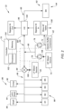
- FIG. 2 schematically illustrates the buffer air assembly 32.
- the buffer air assembly 32 of FIG. 2 includes an electric buffer compressor 62, a supply header 64, a low-pressure header (LP header) 66, and a high-pressure header (HP header) 68.
- the buffer air assembly may further include a controller 70.
- the electric buffer compressor 62 includes an air outlet 72 connected in fluid communication with the supply header 64.
- the electric buffer compressor 62 is configured to produce and supply pressurized air to the supply header 64.
- the electric buffer compressor 62 includes an electric motor which drives the electric buffer compressor 62 (e.g., a centrifugal compressor rotor) to compress air and direct the resultant pressurized air to the supply header 64.
- the electric buffer compressor 62 e.g., the electric motor
- the electric buffer compressor 62 may be electrically connected to an electric distribution system or other electric power source of the engine 20 and/or an aircraft on which the engine 20 is installed.
- the electric buffer compressor 62 (e.g., the electric motor) may be electrically connected with a battery, a generator, an auxiliary power unit (APU), or the like to receive power for operation of the electric buffer compressor 62.
- the present disclosure is not limited to the foregoing exemplary electrical power supply configurations.
- the electric buffer compressor 62 further includes an air inlet (not shown) through which the electric buffer compressor 62 draws air for compression and supply to the supply header 64.
- the air inlet may be configured to draw ambient air from any ambient air location or other air source such as, but not limited to, the bypass flow path 60, a compartment of the engine 20, an exterior of the engine 20, a compressor of the engine 20 (e.g., the low-pressure compressor 24A or the high-pressure compressor 24B), or the like.
- the bypass flow path 60 a compartment of the engine 20, an exterior of the engine 20, a compressor of the engine 20 (e.g., the low-pressure compressor 24A or the high-pressure compressor 24B), or the like.
- the supply header 64 of FIG. 2 is connected in fluid communication with and between the electric buffer compressor 62, the LP header 66, and the HP header 68.
- the supply header 64 of FIG. 2 is further connected in fluid communication with a high-pressure bleed air (HP bleed) source 74.
- the HP bleed source 74 may be, for example, an intermediate stage (e.g., a third or fourth stage) of the high-pressure compressor 24B (see FIG. 1 ).
- the supply header 64 of FIG. 2 includes a first check valve 76 and a second check valve 78 configured to direct pressurized air from the electric buffer compressor 62 and the HP bleed source 74, respectively, to a common supply header line 80.
- the first check valve 76 is disposed in the supply header 64 between the electric buffer compressor 62 (e.g., the air outlet 72) and the common supply header line 80.
- the first check valve 76 is configured to obstruct (e.g., completely or substantially completely block) air flow in a direction from the common supply header line 80 to the electric buffer compressor 62 (e.g., the air outlet 72).
- the second check valve 78 is disposed in the supply header 64 between the HP bleed source 74 and the common supply header line 80.
- the second check valve 78 is configured to obstruct (e.g., completely or substantially completely block) air flow in a direction from the common supply header line 80 to the HP bleed source 74.
- the LP header 66 is selectively connected in fluid communication with the supply header 64 and a low-pressure bleed air (LP bleed) source 82 by a buffer switching valve 84.
- LP bleed low-pressure bleed air
- the LP header 66 may be connected in fluid communication with the supply header 64 to receive pressurized air from the supply header 64.
- the LP header 66 may be fluidly isolated from the LP bleed source 82.
- the LP header 66 may be connected in fluid communication with the LP bleed source 82 to receive pressurized air from the LP bleed source 82.
- the LP header 66 may be fluidly isolated from the supply header 64.
- the LP bleed source 82 may be, for example, an intermediate stage or discharge of the low-pressure compressor 24A (see FIG. 1 ).
- the LP header 66 is connected in fluid communication with one or more low-pressure bleed air loads (LP loads) 86 downstream of the buffer switching valve 84.
- the LP loads 86 of FIG. 2 include one or more bearing compartments 88 (e.g., for the bearing assemblies 56; see FIG. 1 ).
- the bearing compartments 88 of FIG. 2 include bearing compartments B1, B2, B3, B5. The present disclosure, however, is not limited to any particular number of the bearing compartments 88.
- the LP header 66 is configured to supply pressurized air to the bearing compartments 88 for air buffering and/or cooling.
- the LP loads 86 of FIG. 2 further include the bladed first compressor rotor 44 and the second shaft 48 (see also FIG. 1 ).
- the bladed first compressor rotor 44 and the second shaft 48 of FIG. 2 are configured to receive pressurized air from the LP header 66 for air cooling.
- the LP loads 86 may additionally include one or more other engine components 90 configured to receive pressurized air from the LP header 66 for thermal conditioning such as, but not limited to, stator vanes, rotor blades, clearance control devices, and the like.
- the present disclosure is not limited to the foregoing exemplary LP loads 86 of FIG. 2 .
- the HP header 68 is connected in fluid communication with the supply header 64 to receive pressurized air from the supply header 64.
- the HP header 68 is connected in fluid communication with one or more high-pressure bleed air loads (HP loads) 92.
- the HP loads 92 of FIG. 2 include one or more bearing compartments 94 (e.g., for the bearing assemblies 56; see FIG. 1 ).
- the bearing compartments 94 of FIG. 2 include bearing compartment B4.
- the present disclosure is not limited to any particular number of the bearing compartments 94.
- the HP header 68 is configured to supply pressurized air to the bearing compartments 94 for air buffering and/or cooling.
- the HP header 68 of FIG. 2 further includes a heat exchanger 96.
- the heat exchanger 96 is configured to cool high-temperature air which may be received from the supply header 64, for example, when the HP bleed source 74 is supplying pressurized air for the supply header 64.
- the heat exchanger 96 of FIG. 2 includes an air inlet 98 and an air outlet 100.
- the air inlet 98 is connected in fluid communication with the supply header 64.
- the air outlet 100 is connected in fluid communication with the HP loads 92 to direct cooled, pressurized air to the HP loads 92.
- the heat exchanger 96 is connected in fluid communication with a cooling fluid source for cooling the pressurized air flowing through the heat exchanger 96 from the air inlet 98 to the air outlet 100.
- the cooling fluid source may be air from the bypass flow path 60 (see FIG. 1 ).
- the present disclosure is not limited to the foregoing exemplary cooling fluid source.
- the controller 70 includes a processor 102 connected in signal communication with memory 104.
- the processor 102 may include any type of computing device, computational circuit, processor(s), CPU, computer, or the like capable of executing a series of instructions that are stored in the memory 104. Instructions can be directly executable or can be used to develop executable instructions. For example, instructions can be realized as executable or non-executable machine code or as instructions in a high-level language that can be compiled to produce executable or non-executable machine code. Further, instructions also can be realized as or can include data. Computer-executable instructions also can be organized in any format, including routines, subroutines, programs, data structures, objects, modules, applications, applets, functions, etc.
- the instructions may include an operating system, and/or executable software modules such as program files, system data, buffers, drivers, utilities, and the like.
- the executable instructions may apply to any functionality described herein to enable the buffer air assembly 32 to accomplish the same algorithmically and/or by coordination of buffer air assembly 32 components.
- the controller 70 may be connected in signal communication with the electric buffer compressor 62, the buffer switching valve 84, and/or one or more sensors 106 (e.g., pressure sensors) of the buffer air assembly 32.
- the present disclosure is not limited to the foregoing exemplary sensor 106 locations illustrated in FIG. 2 .
- the memory 104 may include a single memory device or a plurality of memory devices; e.g., a computer-readable storage device that can be read, written, or otherwise accessed by a general purpose or special purpose computing device, including any processing electronics and/or processing circuitry capable of executing instructions.
- the present disclosure is not limited to any particular type of memory device, which may be non-transitory, and may include read-only memory, random access memory, volatile memory, non-volatile memory, static memory, dynamic memory, flash memory, cache memory, volatile or non-volatile semiconductor memory, optical disk storage, magnetic disk storage, magnetic tape, other magnetic storage devices, or any other medium capable of storing one or more instructions, and/or any device that stores digital information.
- the memory device(s) may be directly or indirectly coupled to the controller 70.
- the controller 70 may include, or may be in communication with, an input device that enables a user to enter data and/or instructions, and may include, or be in communication with, an output device configured, for example to display information (e.g., a visual display or a printer), or to transfer data, etc. Communications between the controller 70 and other electrical and/or electronic components of the buffer air assembly 32 may be via a hardwire connection or via a wireless connection.
- portions of the controller 70 may assume various forms (e.g., digital signal processor, analog device, etc.) capable of performing the functions described herein.
- the controller 70 may form or otherwise be part of an electronic engine controller (EEC) for the engine 20.
- the EEC may control operating parameters of the engine 20 including, but not limited to, fuel flow, stator vane position (e.g., variable compressor inlet guide vane (IGV) position), compressor air bleed valve position, shaft (e.g., first shaft 42 and/or second shaft 48) torque and/or rotation speed, etc. so as to control an engine power or performance of the engine 20.
- the EEC may modulate fuel flow to the combustor 34 to obtain a desired output power of the engine 20.
- the EEC may modulate the fuel flow using a closed-loop process in which an output power or other operating parameter of the engine 20 is measured and fuel flow is increased or decreased as a function of the measured output power or operational parameter.
- the EEC may be part of a full authority digital engine control (FADEC) system for the engine 20.
- FADEC full authority digital engine control
- the buffer air assembly 32 and its electric buffer compressor 62 may be used to facilitate a suitable supply of buffer air during operating conditions of the engine 20 such as, but not limited to, a startup sequence for the engine 20 in which compressor bleed air (e.g., from the HP bleed source 74 and/or the LP bleed source 82) may initially be insufficient for providing suitable bearing compartment 88, 94 buffering.
- the startup sequence for the engine 20, including operation of the buffer air assembly 32 and its electric buffer compressor 62 may be controlled by the controller 70 in accordance with a startup sequence schedule or other control regime.
- the controller 70 may control (e.g., energize) the electric buffer compressor 62 to direct pressurized air to the LP header 66 and the HP header 68 through the supply header 64.
- the controller 70 may additionally control an air-powered starter motor or other engine starting assembly to drive initial rotation, for example, of the first rotational assembly 36 (e.g., the high-pressure spool; see FIG. 1 ).
- the present disclosure is not limited to the foregoing exemplary engine starting assembly configuration.
- air pressure from the HP bleed source 74 will increase such that the HP bleed source 74 may supply pressurized air for the LP loads 86 and the HP loads 92.
- the controller 70 may then deenergize the electric buffer compressor 62.
- the controller 70 may deenergize the electric buffer compressor 62 based on a predetermined period of time having elapsed since initiation of the startup sequence.
- the controller 70 may deenergize the electric buffer compressor 62 based on a measured air pressure from the HP bleed source 74 (e.g., using the sensors 106). For example, the controller 70 may deenergize the electric buffer compressor in response to identification of the measured air pressure from the HP bleed source 74 greater than or equal to a pressure threshold (e.g., a predetermined pressure threshold value indicative of sufficient pressurized air for buffering).
- the controller 70 may control the buffer switching valve 84 to isolate the LP header 66 from the supply header 64 and to direct pressurized air from the LP bleed source 82 to the LP loads 86 when the pressurized air from the LP bleed source 82 is sufficient for facilitating buffering and/or cooling for the LP loads 86.
- the controller 70 may position the buffer switching valve 84 to isolate the LP header 66 from the supply header 64 and to direct pressurized air from the LP bleed source 82 to the LP loads 86, for example, based on a predetermined period of time having elapsed since initiation of the startup sequence, one or more sensor 106 measurements, a programmed engine startup schedule, etc.
- the controller 70 may position the buffer switching valve 84 based on a measured air pressure from the LP bleed source 82 (e.g., using the sensors 106).
- the controller 70 may position the buffer switching valve 84 in response to identification of the measured air pressure from the LP bleed source 82 greater than or equal to a pressure threshold (e.g., a predetermined pressure threshold value indicative of sufficient pressurized air for buffering).
- a pressure threshold e.g., a predetermined pressure threshold value indicative of sufficient pressurized air for buffering.
- the configuration of the electric buffer compressor 62 and the HP bleed source 74 in fluid communication with the common supply header line 80 may allow the HP bleed source 74 to still provide pressurized air to facilitate at least some buffering and/or cooling for the LP loads 86 and the HP loads 92 during the startup sequence.
- buffer air assembly 32 While the operation of the buffer air assembly 32 is described above for an engine 20 startup sequence, it should be understood that the present disclosure electric buffer compressor 62 may additionally or alternatively be operated with the buffer air assembly 32 for an engine 20 shutdown sequence or another operating condition of the engine 20 in which compressor bleed air (e.g., from the HP bleed source 74 and/or the LP bleed source 82) may not be available or may not provide suitable pressurized air flow for buffering and/or cooling the LP loads 86 and/or the HP loads 92.
- compressor bleed air e.g., from the HP bleed source 74 and/or the LP bleed source 82
- the supply header 64 may additionally include a blow-off valve 108 connected in fluid communication with the electric buffer compressor 62 downstream of the air outlet 72.
- the blow-off valve 108 may be connected in fluid communication with the electric buffer compressor 62 at (e.g., on, adjacent, or proximate) and/or downstream of the air outlet 72 and upstream of the first check valve 76, as shown in FIG. 2 .
- the blow-off valve 108 may be configured as a pressure relief valve to prevent a surge of the electric buffer compressor 62 during certain operating conditions of the buffer air assembly 32.
- an increase of the air pressure from the HP bleed source 74 above an outlet air pressure of the electric buffer compressor 62 may cause the first check valve 76 to shut, potentially causing a sudden increase in the outlet air pressure of the electric buffer compressor 62 (e.g., a surge).
- the blow-off valve 108 may relieve the air pressure at the air outlet 72 until the electric buffer compressor 62 can be deenergized (e.g., by the controller 70).
- the controller 70 may monitor the air pressure from the HP bleed source 74 and deenergize the electric buffer compressor 62 before the air pressure from the HP bleed source 74 increases above the outlet air pressure of the electric buffer compressor 62.
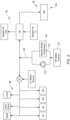
- FIG. 3 schematically illustrates another embodiment of the buffer air assembly 32.
- the electric buffer compressor 62 of FIG. 3 includes an air inlet 110 connected in fluid communication with and downstream of the HP bleed source 74.
- the electric buffer compressor 62 may be arranged in parallel with a check valve 112, as shown in FIG. 3 , such that the HP bleed source 74 may direct pressurized air to the electric buffer compressor 62 and the check valve 112 and the electric buffer compressor 62 and/or the check valve 112 may direct pressurized air to the common supply header line 80.
- the buffer air assembly 32 configuration of FIG. 3 facilitates boosting pressurized air from the HP bleed source 74 with the electric buffer compressor 62 to provide suitable pressurized air flow for buffering and/or cooling the LP loads 86 and/or the HP loads 92.
- the buffer air assembly 32 configuration of FIG. 3 also facilitates elimination of a check valve, in comparison to the buffer air assembly 32 of FIG. 2 , thereby reducing buffer air assembly 32 weight and complexity.
- the buffer air assembly 32 configuration of FIG. 3 also exposes the electric buffer compressor 62 to high-temperature pressurized air from the HP bleed source 74.
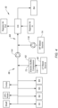
- FIG. 4 schematically illustrates another embodiment of the buffer air assembly 32.
- the electric buffer compressor 62 of FIG. 4 includes the air inlet 110 connected in fluid communication with and downstream of the LP bleed source 82 and the air outlet 72 connected in fluid communication with the LP header 66.
- the LP header 66 of FIG. 4 is connected in fluid communication with the HP header 68 by a check valve 114.
- the check valve 114 is configured to direct pressurized air from the LP header 66 to the HP header 68.
- the check valve 114 is configured to obstruct (e.g., completely or substantially completely block) air flow in a direction from the HP header 68 to the LP header 66.
- the HP bleed source 74 is connected in fluid communication with the HP header 68 by a check valve 116.
- the check valve 116 is configured to direct pressurized air from the HP bleed source 74 to the HP header 68.
- the check valve 116 is configured to obstruct (e.g., completely or substantially completely block) air flow in a direction from the HP header 68 to the HP bleed source 74.
- the electric buffer compressor 62 may be arranged in parallel with a check valve, similar to the electric buffer compressor 62 configuration shown in FIG. 3 , such that the LP bleed source 82 may direct pressurized air to the electric buffer compressor 62 and the check valve and the electric buffer compressor 62 and/or the check valve may direct pressurized air to the LP header 66.
- the buffer air assembly 32 configuration of FIG. 4 may facilitate elimination of a buffer switching valve (e.g., the buffer switching valve 84; see FIG. 2 ), thereby reducing buffer air assembly 32 weight and complexity.
- the buffer air assembly 32 configuration of FIG. 4 also exposes the electric buffer compressor 62 to high-temperature pressurized air from the LP bleed source 82 to a less degree in comparison to the buffer air assembly 32 configuration of FIG. 3 .
- FIG. 5 schematically illustrates another embodiment of the buffer air assembly 32.
- the electric buffer compressor 62 of FIG. 5 includes the air outlet 72 connected in fluid communication with the supply header 64.
- the supply header 64 is connected in fluid communication with the LP header 66 by a check valve 118.
- the check valve 118 is configured to direct pressurized air from the supply header 64 to the LP header 66.
- the check valve 118 is configured to obstruct (e.g., completely or substantially completely block) air flow in a direction from the LP header 66 to the supply header 64.
- the LP bleed source 82 is connected in fluid communication with the LP header 66 by a check valve 120.
- the check valve 120 is configured to direct pressurized air from the LP bleed source 82 to the LP header 66.
- the check valve 120 is configured to obstruct (e.g., completely or substantially completely block) air flow in a direction from the LP header 66 to the LP bleed source 82.
- the supply header 64 is connected in fluid communication with the HP header 68 by a check valve 122.
- the check valve 122 is configured to direct pressurized air from the supply header 64 to the HP header 68.
- the check valve 122 is configured to obstruct (e.g., completely or substantially completely block) air flow in a direction from the HP header 68 to the supply header 64.
- the HP bleed source 74 is connected in fluid communication with the HP header 68 by a check valve 124.
- the check valve 124 is configured to direct pressurized air from the HP bleed source 74 to the HP header 68.
- the check valve 124 is configured to obstruct (e.g., completely or substantially completely block) air flow in a direction from the HP header 68 to the HP bleed source 74.
- the buffer air assembly 32 configuration of FIG. 5 may facilitate elimination of a buffer switching valve (e.g., the buffer switching valve 84; see FIG. 2 ), thereby reducing buffer air assembly 32 weight and complexity.
- any one of these structures may describe the operations as a sequential process, many of the operations can be performed in parallel or concurrently.
- the order of the operations may be rearranged.
- a process may correspond to a method, a function, a procedure, a subroutine, a subprogram, etc.
Landscapes
- Engineering & Computer Science (AREA)
- Chemical & Material Sciences (AREA)
- Combustion & Propulsion (AREA)
- Mechanical Engineering (AREA)
- General Engineering & Computer Science (AREA)
- Structures Of Non-Positive Displacement Pumps (AREA)
Applications Claiming Priority (1)
| Application Number | Priority Date | Filing Date | Title |
|---|---|---|---|
| US18/224,908 US12378893B2 (en) | 2023-07-21 | 2023-07-21 | Buffer air assembly for an aircraft engine |
Publications (1)
| Publication Number | Publication Date |
|---|---|
| EP4495404A1 true EP4495404A1 (fr) | 2025-01-22 |
Family
ID=91960589
Family Applications (1)
| Application Number | Title | Priority Date | Filing Date |
|---|---|---|---|
| EP24189806.3A Pending EP4495404A1 (fr) | 2023-07-21 | 2024-07-19 | Ensemble d'air tampon pour moteur d'avion |
Country Status (2)
| Country | Link |
|---|---|
| US (1) | US12378893B2 (fr) |
| EP (1) | EP4495404A1 (fr) |
Citations (5)
| Publication number | Priority date | Publication date | Assignee | Title |
|---|---|---|---|---|
| US20110203293A1 (en) * | 2010-02-19 | 2011-08-25 | United Technologies Corporation | Bearing compartment pressurization and shaft ventilation system |
| US20130192240A1 (en) * | 2012-01-31 | 2013-08-01 | Peter M. Munsell | Buffer system for a gas turbine engine |
| US20160084111A1 (en) * | 2013-04-10 | 2016-03-24 | Nuovo Pignone Srl | Methods and systems for preventing lube oil leakage in gas turbines |
| US20180128176A1 (en) * | 2016-11-08 | 2018-05-10 | United Technologies Corporation | Intercooled cooled cooling integrated air cycle machine |
| US20230148411A1 (en) * | 2019-02-05 | 2023-05-11 | Raytheon Technologies Corporation | Power assisted engine start bleed system |
Family Cites Families (2)
| Publication number | Priority date | Publication date | Assignee | Title |
|---|---|---|---|---|
| US10519963B2 (en) * | 2016-06-20 | 2019-12-31 | United Technologies Corporation | Engine bleed air system with waste gate valve for compressor surge management |
| US11746701B2 (en) | 2018-08-09 | 2023-09-05 | Rolls-Royce North American Technologies, Inc. | Bleed expander cooling with turbine |
-
2023
- 2023-07-21 US US18/224,908 patent/US12378893B2/en active Active
-
2024
- 2024-07-19 EP EP24189806.3A patent/EP4495404A1/fr active Pending
Patent Citations (5)
| Publication number | Priority date | Publication date | Assignee | Title |
|---|---|---|---|---|
| US20110203293A1 (en) * | 2010-02-19 | 2011-08-25 | United Technologies Corporation | Bearing compartment pressurization and shaft ventilation system |
| US20130192240A1 (en) * | 2012-01-31 | 2013-08-01 | Peter M. Munsell | Buffer system for a gas turbine engine |
| US20160084111A1 (en) * | 2013-04-10 | 2016-03-24 | Nuovo Pignone Srl | Methods and systems for preventing lube oil leakage in gas turbines |
| US20180128176A1 (en) * | 2016-11-08 | 2018-05-10 | United Technologies Corporation | Intercooled cooled cooling integrated air cycle machine |
| US20230148411A1 (en) * | 2019-02-05 | 2023-05-11 | Raytheon Technologies Corporation | Power assisted engine start bleed system |
Also Published As
| Publication number | Publication date |
|---|---|
| US20250027422A1 (en) | 2025-01-23 |
| US12378893B2 (en) | 2025-08-05 |
Similar Documents
| Publication | Publication Date | Title |
|---|---|---|
| US11536198B2 (en) | Gas turbine engine cooling system control | |
| US11473496B2 (en) | Transient operation control of a hybrid gas turbine engine | |
| US12000345B2 (en) | Surge recovery system and methods | |
| CN109477400B (zh) | 涡轮发动机及操作方法 | |
| EP3184756A1 (fr) | Procédé et système de modulation de la marge de décrochage en fonction de l'état du moteur | |
| EP3702599B1 (fr) | Système et procédé de diagnostic de l'état de santé d'un compresseur d'alimentation d'une unité de puissance auxiliaire | |
| US20240263562A1 (en) | Transient control of a thermal transport bus | |
| EP4119775B1 (fr) | Système et procédé actif de commande de jeu pour moteur d'avion | |
| US12378893B2 (en) | Buffer air assembly for an aircraft engine | |
| EP4495403A1 (fr) | Ensemble d'air tampon pour moteur d'aéronef | |
| EP4372220A1 (fr) | Système d'extraction de puissance de moteur et son procédé d'utilisation | |
| EP4368500A1 (fr) | Systèmes et procédés de commande de pression de fluide d'unité de commande d'hélice | |
| US11525370B2 (en) | Method and system for mitigating rotor bow in a turbo machine | |
| US20260009361A1 (en) | Gas turbine engine buffer air augmentation system and method | |
| US12442303B1 (en) | Method of mitigating rotor bow in a turbine engine rotor | |
| US12535016B2 (en) | Systems and methods for identifying insufficient starter acceleration for an aircraft engine | |
| EP4733564A1 (fr) | Systèmes et procédés de fonctionnement d'un moteur d'aéronef à l'aide de multiples types de carburant | |
| US20260117704A1 (en) | Systems and methods for operating an aircraft engine using multiple fuel types | |
| US20260117712A1 (en) | Systems and methods for operating an aircraft engine using multiple fuel types | |
| EP4733560A2 (fr) | Systèmes et procédés de fonctionnement d'un moteur d'aéronef à l'aide de multiples types de carburant | |
| US20260117979A1 (en) | Systems and methods for operating an aircraft engine using multiple fuel types | |
| US20260117710A1 (en) | Systems and methods for operating an aircraft engine using multiple fuel types | |
| US20250101877A1 (en) | System and method for identifying rubbing conditions for engine rotational equipment | |
| CN115126554A (zh) | 配有使用电机管理转子模式的控制系统的燃气涡轮发动机 | |
| CA3272597A1 (en) | Partial-admission turbine assembly for an aircraft and method for controlling same |
Legal Events
| Date | Code | Title | Description |
|---|---|---|---|
| PUAI | Public reference made under article 153(3) epc to a published international application that has entered the european phase |
Free format text: ORIGINAL CODE: 0009012 |
|
| STAA | Information on the status of an ep patent application or granted ep patent |
Free format text: STATUS: THE APPLICATION HAS BEEN PUBLISHED |
|
| AK | Designated contracting states |
Kind code of ref document: A1 Designated state(s): AL AT BE BG CH CY CZ DE DK EE ES FI FR GB GR HR HU IE IS IT LI LT LU LV MC ME MK MT NL NO PL PT RO RS SE SI SK SM TR |
|
| STAA | Information on the status of an ep patent application or granted ep patent |
Free format text: STATUS: REQUEST FOR EXAMINATION WAS MADE |
|
| 17P | Request for examination filed |
Effective date: 20250721 |