EP4495421A2 - Fondation pour une éolienne - Google Patents
Fondation pour une éolienne Download PDFInfo
- Publication number
- EP4495421A2 EP4495421A2 EP24194231.7A EP24194231A EP4495421A2 EP 4495421 A2 EP4495421 A2 EP 4495421A2 EP 24194231 A EP24194231 A EP 24194231A EP 4495421 A2 EP4495421 A2 EP 4495421A2
- Authority
- EP
- European Patent Office
- Prior art keywords
- section
- tower
- foundation
- horizontal elements
- base
- Prior art date
- Legal status (The legal status is an assumption and is not a legal conclusion. Google has not performed a legal analysis and makes no representation as to the accuracy of the status listed.)
- Pending
Links
Images
Classifications
-
- E—FIXED CONSTRUCTIONS
- E02—HYDRAULIC ENGINEERING; FOUNDATIONS; SOIL SHIFTING
- E02D—FOUNDATIONS; EXCAVATIONS; EMBANKMENTS; UNDERGROUND OR UNDERWATER STRUCTURES
- E02D27/00—Foundations as substructures
- E02D27/32—Foundations for special purposes
- E02D27/42—Foundations for poles, masts or chimneys
- E02D27/425—Foundations for poles, masts or chimneys specially adapted for wind motors masts
-
- F—MECHANICAL ENGINEERING; LIGHTING; HEATING; WEAPONS; BLASTING
- F03—MACHINES OR ENGINES FOR LIQUIDS; WIND, SPRING, OR WEIGHT MOTORS; PRODUCING MECHANICAL POWER OR A REACTIVE PROPULSIVE THRUST, NOT OTHERWISE PROVIDED FOR
- F03D—WIND MOTORS
- F03D13/00—Assembly, mounting or commissioning of wind motors; Arrangements specially adapted for transporting wind motor components
- F03D13/20—Arrangements for mounting or supporting wind motors; Masts or towers for wind motors
- F03D13/22—Foundations specially adapted for wind motors
-
- E—FIXED CONSTRUCTIONS
- E02—HYDRAULIC ENGINEERING; FOUNDATIONS; SOIL SHIFTING
- E02D—FOUNDATIONS; EXCAVATIONS; EMBANKMENTS; UNDERGROUND OR UNDERWATER STRUCTURES
- E02D2250/00—Production methods
- E02D2250/0023—Cast, i.e. in situ or in a mold or other formwork
-
- E—FIXED CONSTRUCTIONS
- E02—HYDRAULIC ENGINEERING; FOUNDATIONS; SOIL SHIFTING
- E02D—FOUNDATIONS; EXCAVATIONS; EMBANKMENTS; UNDERGROUND OR UNDERWATER STRUCTURES
- E02D2300/00—Materials
- E02D2300/0004—Synthetics
- E02D2300/0018—Cement used as binder
- E02D2300/002—Concrete
-
- Y—GENERAL TAGGING OF NEW TECHNOLOGICAL DEVELOPMENTS; GENERAL TAGGING OF CROSS-SECTIONAL TECHNOLOGIES SPANNING OVER SEVERAL SECTIONS OF THE IPC; TECHNICAL SUBJECTS COVERED BY FORMER USPC CROSS-REFERENCE ART COLLECTIONS [XRACs] AND DIGESTS
- Y02—TECHNOLOGIES OR APPLICATIONS FOR MITIGATION OR ADAPTATION AGAINST CLIMATE CHANGE
- Y02E—REDUCTION OF GREENHOUSE GAS [GHG] EMISSIONS, RELATED TO ENERGY GENERATION, TRANSMISSION OR DISTRIBUTION
- Y02E10/00—Energy generation through renewable energy sources
- Y02E10/70—Wind energy
- Y02E10/72—Wind turbines with rotation axis in wind direction
-
- Y—GENERAL TAGGING OF NEW TECHNOLOGICAL DEVELOPMENTS; GENERAL TAGGING OF CROSS-SECTIONAL TECHNOLOGIES SPANNING OVER SEVERAL SECTIONS OF THE IPC; TECHNICAL SUBJECTS COVERED BY FORMER USPC CROSS-REFERENCE ART COLLECTIONS [XRACs] AND DIGESTS
- Y02—TECHNOLOGIES OR APPLICATIONS FOR MITIGATION OR ADAPTATION AGAINST CLIMATE CHANGE
- Y02E—REDUCTION OF GREENHOUSE GAS [GHG] EMISSIONS, RELATED TO ENERGY GENERATION, TRANSMISSION OR DISTRIBUTION
- Y02E10/00—Energy generation through renewable energy sources
- Y02E10/70—Wind energy
- Y02E10/728—Onshore wind turbines
Definitions
- the invention relates to a foundation for a wind turbine with a first base-like section, cast essentially from concrete at the installation site, with at least one tower fastening element located therein and cast in place, on which a tower of the wind turbine can be arranged and with which the tower of the wind turbine can be connected, and a second essentially horizontally extending section as a flat foundation body, wherein the second section is arranged in connection with the first section, and wherein the second section of the foundation essentially consists of at least three prefabricated horizontal elements, preferably made of reinforced concrete.
- the invention further relates to a method for erecting a foundation for a wind turbine.
- Foundations for wind turbines are essentially constructed as in-situ concrete foundations. For this purpose, a pit is dug at the construction site and covered with a blind layer. The formwork and reinforcement are then erected and the whole thing is filled with concrete on site. A flat body is constructed, possibly with a base, see for example US 20160369520 A1 In addition to the transport costs of delivering the concrete, formwork and reinforcement, this is very labor- and time-intensive on site. Quality assurance is also complex and, depending on the weather, problematic. Furthermore, dismantling after the end of the wind turbine's service life is expensive and very complex.
- EP 22563387 A1 discloses a foundation for a wind turbine.
- a foundation is built from prefabricated concrete parts after appropriate delivery on site. It contains a flat section and a base-like section.
- the ribs have horizontally projecting anchor elements that extend radially into the center of the foundation when assembled. Plates are provided below and above the anchors.
- the in-situ concrete is poured into the cavity thus formed in order to connect the anchors to one another and form a central body. This only reduces the disadvantages mentioned above insignificantly.
- the object of the invention is therefore to overcome the aforementioned disadvantages and to make foundations for wind turbines, in particular for wind turbines with concrete towers, economically erectable from prefabricated elements.
- the object according to the invention is achieved with regard to the foundation in that the at least three horizontal elements (22) each have at least one base section with a stiffening element extending substantially vertically thereon, that the horizontal elements (22) can be arranged depending on the parameters of the tower to be erected, in particular the tower radius, and that there is a distance between each of the horizontal elements.
- a further teaching of the invention provides that the gap is/will be covered with at least one covering element. It has been shown that this makes it easy to increase the load by adding soil to the top of the foundation.
- a further teaching of the invention provides that the first section has reinforcements that are cast in place. These are preferably at least partially prefabricated. This makes it easy to produce a base that meets the necessary static requirements.
- a further teaching of the invention provides that the at least three horizontal elements have at least one connecting element which emerges from their side facing the first section and is cast in place in the first section. This will easily produce a correspondingly simple and secure connection of the horizontal elements to the base.
- a further teaching of the invention provides that the at least one tower fastening element is an anchor basket.
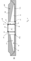
- a preferred embodiment of a foundation 10 is arranged in a pit 101 in the ground 100 on a sub-base layer 102. They have a first base-like section 11 and a second flat section 12 formed from horizontal elements 22. Furthermore, a third section (not shown) can optionally be provided under the first section 11 or the first section can be designed as a projection 21 extending downwards over the second section, which would then each preferably be provided in a recess 103.
- the first section 11 is designed as a base 20.
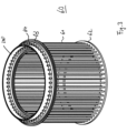
- an anchor basket 60 is installed as a tower fastening element, see Figure 3 , as well as reinforcements (not shown).
- the anchor basket 60 as an example of a tower fastening element is made up of vertical bars 61 and rings 62, 63 arranged at the top and bottom, which are firmly connected to one another.
- the upper ring 63 with the protruding bar sections 64 protrudes from the concrete of the base 20.
- the connecting flange 200 of the tower of the wind turbine is connected to this part of the anchor basket, for example by means of screw connections.
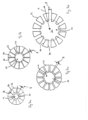
- the second section 12 is flat. Alternatively, it can also be made in a star shape.
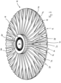
- Fig.2 shows a spatial view of the foundation 10.
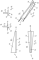
- the second section 12 is made of horizontal elements 22 in the form of rib elements. These are shown in the Fig. 5a to 5e These extend from the base 20 They have a base plate 23, which is designed, for example, trapezoidal, so that all assembled base plates form a polygonal surface (see Fig. 2 ) that approximates a circle shape. Alternatively, circle segments (see Fig. 7a to 7d ) or a mixed form of a circular segment and a trapezoidal shape is possible.
- Distances B are provided between the side walls 44 of the base plates 23, which depend on the diameter of the tower to be erected.
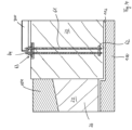
- a stiffening wall 26 is arranged at right angles to the base plate 23, the height of which decreases, for example, from the inner end 24 to the outer end 27 of the base plate 23. Between two adjacent stiffening walls 26, an upwardly open cavity 28 is formed, into which fill soil 104 can be introduced, whereby a load can be applied to the second section 12 of the foundation 10.
- connecting elements 29 are preferably provided in the form of reinforcing bars, which emerge from the base plate and/or from the stiffening wall 24 and, in the assembled state, protrude into the base, for example in the direction of the anchor cage, and form a holding connection with the concrete of the base 20.
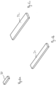
- the distances B are covered by cover plates 30, 31, 32 in order to achieve a virtually continuous surface below the cavity 28. This increases the load effect of the floor 104.
- a second section 12 As shown schematically, it is possible to form a second section 12 with one and the same horizontal element 22, which has bases 20 of different sizes, by moving the horizontal elements 22 inwards or outwards along a beam emanating from the centre, as shown in Fig. 7d by a double arrow A. Inwards, this is limited by the fact that the side surfaces 44 of the base plates 23 of the horizontal elements 22 touch each other. Outwards, this depends on the radius of the tower to be erected (not shown) and thus also the radius of the anchor basket. A distance B is preferably the same over the entire length of the side surfaces 44 from the inner end 24 to the outer end 27, so that two side surfaces 44 are arranged parallel to each other. This allows in a simple manner, preferably with a single horizontal element 22 Foundations for towers with different diameters can be built.
- the cavity 28 is then covered by the cover plates 30, 31, 32 (see Fig. 6a -6c ) covered.
- the foundation 10 is erected in an excavation pit 100, for example on a blind layer 102, by arranging at least one tower fastening element/anchor cage 60 in the base section 11 of the foundation 10.
- the horizontal elements 22 are arranged radially around the tower fastening element 60 so that at least one connecting element 29 emerging from the horizontal element 22 projects into the base section 11 or the tower fastening element 60, the horizontal elements 22 being arranged so that there is a distance B between the horizontal elements 22.
- reinforcements are introduced into the base section 11. These can, for example, already be pre-produced and introduced as elements (not shown).
- formwork is provided which spatially delimits the base section. The in-situ concrete is then introduced into the formwork in this space.
- the distances B are closed off towards the cavity 28 with cover elements 30, 31, 32.
- the formwork is removed, for example.
- Backfill soil 104 is then introduced into the cavity 28 as a load.
- the tower of the wind turbine can then be erected on the base 20 in conjunction with the tower fastening element 60.
Landscapes
- Engineering & Computer Science (AREA)
- Life Sciences & Earth Sciences (AREA)
- General Engineering & Computer Science (AREA)
- Mining & Mineral Resources (AREA)
- Paleontology (AREA)
- Civil Engineering (AREA)
- General Life Sciences & Earth Sciences (AREA)
- Structural Engineering (AREA)
- Sustainable Development (AREA)
- Sustainable Energy (AREA)
- Chemical & Material Sciences (AREA)
- Combustion & Propulsion (AREA)
- Mechanical Engineering (AREA)
- Foundations (AREA)
- Wind Motors (AREA)
Applications Claiming Priority (3)
| Application Number | Priority Date | Filing Date | Title |
|---|---|---|---|
| DE102019126558.4A DE102019126558A1 (de) | 2019-10-02 | 2019-10-02 | Fundament für eine Windkraftanlage |
| EP20796698.7A EP4038240B1 (fr) | 2019-10-02 | 2020-10-02 | Fondation pour turbine d'éolienne |
| PCT/EP2020/077693 WO2021064190A1 (fr) | 2019-10-02 | 2020-10-02 | Fondation pour une éolienne |
Related Parent Applications (1)
| Application Number | Title | Priority Date | Filing Date |
|---|---|---|---|
| EP20796698.7A Division EP4038240B1 (fr) | 2019-10-02 | 2020-10-02 | Fondation pour turbine d'éolienne |
Publications (2)
| Publication Number | Publication Date |
|---|---|
| EP4495421A2 true EP4495421A2 (fr) | 2025-01-22 |
| EP4495421A3 EP4495421A3 (fr) | 2025-05-07 |
Family
ID=73013362
Family Applications (2)
| Application Number | Title | Priority Date | Filing Date |
|---|---|---|---|
| EP20796698.7A Active EP4038240B1 (fr) | 2019-10-02 | 2020-10-02 | Fondation pour turbine d'éolienne |
| EP24194231.7A Pending EP4495421A3 (fr) | 2019-10-02 | 2020-10-02 | Fondation pour une éolienne |
Family Applications Before (1)
| Application Number | Title | Priority Date | Filing Date |
|---|---|---|---|
| EP20796698.7A Active EP4038240B1 (fr) | 2019-10-02 | 2020-10-02 | Fondation pour turbine d'éolienne |
Country Status (8)
| Country | Link |
|---|---|
| US (1) | US20230076691A1 (fr) |
| EP (2) | EP4038240B1 (fr) |
| CN (1) | CN114729626A (fr) |
| CA (1) | CA3162517A1 (fr) |
| DE (1) | DE102019126558A1 (fr) |
| ES (1) | ES3001155T3 (fr) |
| PL (1) | PL4038240T3 (fr) |
| WO (1) | WO2021064190A1 (fr) |
Families Citing this family (3)
| Publication number | Priority date | Publication date | Assignee | Title |
|---|---|---|---|---|
| DE102018131443A1 (de) * | 2018-12-07 | 2020-06-10 | Wobben Properties Gmbh | Fundamentanordnung, Adapterelement, Spannvorrichtung und Turm einer Windenergieanlage sowie Verfahren zum Vorspannen eines Turms einer Windenergieanlage |
| WO2022252754A1 (fr) * | 2021-06-03 | 2022-12-08 | 中国华能集团清洁能源技术研究院有限公司 | Ensemble préfabriqué et fondation d'éolienne combinée en béton coulé en place |
| DE102021122183A1 (de) | 2021-08-26 | 2023-03-02 | Smart & Green Mukran Concrete Gmbh | Fundament für einen Turm für eine Windkraftanlage |
Citations (2)
| Publication number | Priority date | Publication date | Assignee | Title |
|---|---|---|---|---|
| WO2008036934A2 (fr) | 2006-09-21 | 2008-03-27 | Ahmed Phuly | Système de fondation modulaire partiellement préfabriqué |
| US20160369520A1 (en) | 2013-05-10 | 2016-12-22 | Are Telecom Incorporated | Modular monopole tower foundation |
Family Cites Families (5)
| Publication number | Priority date | Publication date | Assignee | Title |
|---|---|---|---|---|
| US6229497B1 (en) * | 1999-09-02 | 2001-05-08 | Mccracken Ronald G. | Antenna mounts |
| DE10321647A1 (de) * | 2003-05-13 | 2004-12-02 | Wobben, Aloys, Dipl.-Ing. | Fundament für eine Windenergieanlage |
| AT517959B1 (de) * | 2016-02-18 | 2017-06-15 | Holcim Technology Ltd | Fundament für ein Windrad |
| AT519190A1 (de) * | 2016-09-26 | 2018-04-15 | Holcim Technology Ltd | Fundament für eine Windmühle |
| DE102018112857A1 (de) * | 2017-12-13 | 2019-06-13 | Universelle-Fertigteil-Fundamente GmbH | Fundament für eine Windkraftanlage |
-
2019
- 2019-10-02 DE DE102019126558.4A patent/DE102019126558A1/de active Pending
-
2020
- 2020-10-02 US US17/762,842 patent/US20230076691A1/en not_active Abandoned
- 2020-10-02 CN CN202080069149.9A patent/CN114729626A/zh active Pending
- 2020-10-02 EP EP20796698.7A patent/EP4038240B1/fr active Active
- 2020-10-02 ES ES20796698T patent/ES3001155T3/es active Active
- 2020-10-02 WO PCT/EP2020/077693 patent/WO2021064190A1/fr not_active Ceased
- 2020-10-02 EP EP24194231.7A patent/EP4495421A3/fr active Pending
- 2020-10-02 CA CA3162517A patent/CA3162517A1/fr active Pending
- 2020-10-02 PL PL20796698.7T patent/PL4038240T3/pl unknown
Patent Citations (2)
| Publication number | Priority date | Publication date | Assignee | Title |
|---|---|---|---|---|
| WO2008036934A2 (fr) | 2006-09-21 | 2008-03-27 | Ahmed Phuly | Système de fondation modulaire partiellement préfabriqué |
| US20160369520A1 (en) | 2013-05-10 | 2016-12-22 | Are Telecom Incorporated | Modular monopole tower foundation |
Also Published As
| Publication number | Publication date |
|---|---|
| US20230076691A1 (en) | 2023-03-09 |
| DE102019126558A1 (de) | 2021-04-08 |
| EP4038240B1 (fr) | 2024-08-14 |
| EP4038240C0 (fr) | 2024-08-14 |
| PL4038240T3 (pl) | 2025-02-10 |
| EP4038240A1 (fr) | 2022-08-10 |
| CN114729626A (zh) | 2022-07-08 |
| ES3001155T3 (es) | 2025-03-04 |
| EP4495421A3 (fr) | 2025-05-07 |
| CA3162517A1 (fr) | 2021-04-08 |
| WO2021064190A1 (fr) | 2021-04-08 |
Similar Documents
| Publication | Publication Date | Title |
|---|---|---|
| EP3781747B1 (fr) | Procédure d'établissement d'un fondement pour une éolienne | |
| EP3724407B1 (fr) | Fondation pour une éolienne | |
| EP4038240B1 (fr) | Fondation pour turbine d'éolienne | |
| EP3183401B1 (fr) | Structure en béton modulaire | |
| DE102024107925A1 (de) | Primärschalentragwerk aus Flächentragwerksmodulen, die aus Elementen bestehen | |
| DE102018121024A1 (de) | Fundament für eine Windkraftanlage | |
| EP4222319A1 (fr) | Fondation pour une éolienne | |
| DE2660867C2 (de) | Verfahren zur Errichtung trichter- oder kegelförmiger Betonbauten | |
| EP4222321B1 (fr) | Fondation d'une éolienne | |
| EP3219879B1 (fr) | Procédé d'installation d'une tour d'éolienne et éolienne correspondante | |
| EP3555390B1 (fr) | Procédé pour construire une tour d'éolienne en béton précontraint, et tour d'éolienne correspondante | |
| DE102021125328A1 (de) | Ankerkorb für ein Fundament für eine Windkraftanlage | |
| EP0645501B1 (fr) | Méthode pour la production de modules préfabriqués pour la construction de bâtiments et module préfabriqué | |
| DE102019126629A1 (de) | Fundament für eine Windkraftanlage | |
| DE102019126587A1 (de) | Fundament für eine Windkraftanlage | |
| EP4248017B1 (fr) | Fondation pour tour d'une station de transmission ou pour la construction d'une ligne aérienne | |
| WO2014023289A2 (fr) | Dispositif et procédé d'édification d'un bâtiment à plusieurs étages à partir d'éléments préfabriqués en béton | |
| DE202021105272U1 (de) | Ankerkorb für ein Fundament für eine Windkraftanlage | |
| WO2023025555A1 (fr) | Fondation de tour d'éolienne | |
| DE202020105643U1 (de) | Fundament für eine Windkraftanlage | |
| DE202020106971U1 (de) | Fundament für eine Windkraftanlage | |
| DE102021105955A1 (de) | Fundament für einen Turm für eine Windkraftanlage | |
| DE102021105960A1 (de) | Fundament für einen Turm für eine Sendeanlage oder für den Freileitungsbau | |
| DE4100141A1 (de) | Tragstruktur aus uebereinander angeordneten stahlbetonfertigteil-sektionen fuer turmartige bauwerke und schornsteine sowie sektion fuer die tragstruktur |
Legal Events
| Date | Code | Title | Description |
|---|---|---|---|
| STAA | Information on the status of an ep patent application or granted ep patent |
Free format text: STATUS: UNKNOWN |
|
| PUAI | Public reference made under article 153(3) epc to a published international application that has entered the european phase |
Free format text: ORIGINAL CODE: 0009012 |
|
| STAA | Information on the status of an ep patent application or granted ep patent |
Free format text: STATUS: THE APPLICATION HAS BEEN PUBLISHED |
|
| AC | Divisional application: reference to earlier application |
Ref document number: 4038240 Country of ref document: EP Kind code of ref document: P |
|
| AK | Designated contracting states |
Kind code of ref document: A2 Designated state(s): AL AT BE BG CH CY CZ DE DK EE ES FI FR GB GR HR HU IE IS IT LI LT LU LV MC MK MT NL NO PL PT RO RS SE SI SK SM TR |
|
| PUAL | Search report despatched |
Free format text: ORIGINAL CODE: 0009013 |
|
| AK | Designated contracting states |
Kind code of ref document: A3 Designated state(s): AL AT BE BG CH CY CZ DE DK EE ES FI FR GB GR HR HU IE IS IT LI LT LU LV MC MK MT NL NO PL PT RO RS SE SI SK SM TR |
|
| RIC1 | Information provided on ipc code assigned before grant |
Ipc: E02D 27/42 20060101ALI20250331BHEP Ipc: F03D 13/20 20160101AFI20250331BHEP |
|
| STAA | Information on the status of an ep patent application or granted ep patent |
Free format text: STATUS: REQUEST FOR EXAMINATION WAS MADE |
|
| 17P | Request for examination filed |
Effective date: 20251106 |