EP4495471A1 - Ensemble de fermeture d'orifice d'eau - Google Patents
Ensemble de fermeture d'orifice d'eau Download PDFInfo
- Publication number
- EP4495471A1 EP4495471A1 EP23461629.0A EP23461629A EP4495471A1 EP 4495471 A1 EP4495471 A1 EP 4495471A1 EP 23461629 A EP23461629 A EP 23461629A EP 4495471 A1 EP4495471 A1 EP 4495471A1
- Authority
- EP
- European Patent Office
- Prior art keywords
- filter part
- port
- assembly
- filter
- flow channel
- Prior art date
- Legal status (The legal status is an assumption and is not a legal conclusion. Google has not performed a legal analysis and makes no representation as to the accuracy of the status listed.)
- Pending
Links
Images




Classifications
-
- F—MECHANICAL ENGINEERING; LIGHTING; HEATING; WEAPONS; BLASTING
- F16—ENGINEERING ELEMENTS AND UNITS; GENERAL MEASURES FOR PRODUCING AND MAINTAINING EFFECTIVE FUNCTIONING OF MACHINES OR INSTALLATIONS; THERMAL INSULATION IN GENERAL
- F16L—PIPES; JOINTS OR FITTINGS FOR PIPES; SUPPORTS FOR PIPES, CABLES OR PROTECTIVE TUBING; MEANS FOR THERMAL INSULATION IN GENERAL
- F16L29/00—Joints with fluid cut-off means
- F16L29/002—Joints with fluid cut-off means joints with taps
-
- F—MECHANICAL ENGINEERING; LIGHTING; HEATING; WEAPONS; BLASTING
- F16—ENGINEERING ELEMENTS AND UNITS; GENERAL MEASURES FOR PRODUCING AND MAINTAINING EFFECTIVE FUNCTIONING OF MACHINES OR INSTALLATIONS; THERMAL INSULATION IN GENERAL
- F16L—PIPES; JOINTS OR FITTINGS FOR PIPES; SUPPORTS FOR PIPES, CABLES OR PROTECTIVE TUBING; MEANS FOR THERMAL INSULATION IN GENERAL
- F16L29/00—Joints with fluid cut-off means
- F16L29/02—Joints with fluid cut-off means with a cut-off device in one of the two pipe ends, the cut-off device being automatically opened when the coupling is applied
-
- B—PERFORMING OPERATIONS; TRANSPORTING
- B64—AIRCRAFT; AVIATION; COSMONAUTICS
- B64D—EQUIPMENT FOR FITTING IN OR TO AIRCRAFT; FLIGHT SUITS; PARACHUTES; ARRANGEMENT OR MOUNTING OF POWER PLANTS OR PROPULSION TRANSMISSIONS IN AIRCRAFT
- B64D11/00—Passenger or crew accommodation; Flight-deck installations not otherwise provided for
- B64D11/04—Galleys
-
- F—MECHANICAL ENGINEERING; LIGHTING; HEATING; WEAPONS; BLASTING
- F16—ENGINEERING ELEMENTS AND UNITS; GENERAL MEASURES FOR PRODUCING AND MAINTAINING EFFECTIVE FUNCTIONING OF MACHINES OR INSTALLATIONS; THERMAL INSULATION IN GENERAL
- F16K—VALVES; TAPS; COCKS; ACTUATING-FLOATS; DEVICES FOR VENTING OR AERATING
- F16K3/00—Gate valves or sliding valves, i.e. cut-off apparatus with closing members having a sliding movement along the seat for opening and closing
- F16K3/02—Gate valves or sliding valves, i.e. cut-off apparatus with closing members having a sliding movement along the seat for opening and closing with flat sealing faces; Packings therefor
- F16K3/04—Gate valves or sliding valves, i.e. cut-off apparatus with closing members having a sliding movement along the seat for opening and closing with flat sealing faces; Packings therefor with pivoted closure members
- F16K3/06—Gate valves or sliding valves, i.e. cut-off apparatus with closing members having a sliding movement along the seat for opening and closing with flat sealing faces; Packings therefor with pivoted closure members in the form of closure plates arranged between supply and discharge passages
- F16K3/08—Gate valves or sliding valves, i.e. cut-off apparatus with closing members having a sliding movement along the seat for opening and closing with flat sealing faces; Packings therefor with pivoted closure members in the form of closure plates arranged between supply and discharge passages with circular plates rotatable around their centres
- F16K3/085—Gate valves or sliding valves, i.e. cut-off apparatus with closing members having a sliding movement along the seat for opening and closing with flat sealing faces; Packings therefor with pivoted closure members in the form of closure plates arranged between supply and discharge passages with circular plates rotatable around their centres the axis of supply passage and the axis of discharge passage being coaxial and parallel to the axis of rotation of the plates
-
- F—MECHANICAL ENGINEERING; LIGHTING; HEATING; WEAPONS; BLASTING
- F16—ENGINEERING ELEMENTS AND UNITS; GENERAL MEASURES FOR PRODUCING AND MAINTAINING EFFECTIVE FUNCTIONING OF MACHINES OR INSTALLATIONS; THERMAL INSULATION IN GENERAL
- F16K—VALVES; TAPS; COCKS; ACTUATING-FLOATS; DEVICES FOR VENTING OR AERATING
- F16K31/00—Actuating devices; Operating means; Releasing devices
- F16K31/44—Mechanical actuating means
- F16K31/52—Mechanical actuating means with crank, eccentric, or cam
- F16K31/528—Mechanical actuating means with crank, eccentric, or cam with pin and slot
- F16K31/5286—Mechanical actuating means with crank, eccentric, or cam with pin and slot comprising a sliding valve
-
- F—MECHANICAL ENGINEERING; LIGHTING; HEATING; WEAPONS; BLASTING
- F16—ENGINEERING ELEMENTS AND UNITS; GENERAL MEASURES FOR PRODUCING AND MAINTAINING EFFECTIVE FUNCTIONING OF MACHINES OR INSTALLATIONS; THERMAL INSULATION IN GENERAL
- F16L—PIPES; JOINTS OR FITTINGS FOR PIPES; SUPPORTS FOR PIPES, CABLES OR PROTECTIVE TUBING; MEANS FOR THERMAL INSULATION IN GENERAL
- F16L35/00—Special arrangements used in connection with end fittings of hoses, e.g. safety or protecting devices
-
- F—MECHANICAL ENGINEERING; LIGHTING; HEATING; WEAPONS; BLASTING
- F16—ENGINEERING ELEMENTS AND UNITS; GENERAL MEASURES FOR PRODUCING AND MAINTAINING EFFECTIVE FUNCTIONING OF MACHINES OR INSTALLATIONS; THERMAL INSULATION IN GENERAL
- F16L—PIPES; JOINTS OR FITTINGS FOR PIPES; SUPPORTS FOR PIPES, CABLES OR PROTECTIVE TUBING; MEANS FOR THERMAL INSULATION IN GENERAL
- F16L37/00—Couplings of the quick-acting type
- F16L37/28—Couplings of the quick-acting type with fluid cut-off means
- F16L37/38—Couplings of the quick-acting type with fluid cut-off means with fluid cut-off means in only one of two pipe-end fittings
- F16L37/47—Couplings of the quick-acting type with fluid cut-off means with fluid cut-off means in only one of two pipe-end fittings with a tap or cock
Definitions
- the present disclosure is concerned with providing a closure assembly for ports in a water system, such as the fill and overflow ports of a water system.
- the water system can, for example, be a system for providing potable or fresh water in an aircraft.
- Water systems often include a tank or storage vessel to store water which can then be plumbed to other parts of the system to provide water to different parts of the system from the storage tank/vessel.
- the tank will need to be periodically re-filled.
- the tank is provided with a fill port to which a fill line, connected to a source of water, is connected for re-filling the tank from the source.
- the tank may also be provided with an overflow or overfill line via which water can exit the tank if the tank is overfilled.
- the overflow water exits from an overflow port on the tank.
- the fill port, and, where present, the overflow port will be open. In some applications, the ports are left open after filling.
- the ports may be provided in an operating panel that is covered by a door or panel when not in use.
- a closure or cap assembly is provided at the ports to close the port(s) when not being filled.
- each port may be provided with its own cap or closure or, alternatively, a single closure can be provided that covers both ports, when closed.
- Such assemblies may be used, for example, in aircraft.
- An aircraft typically has water stations in the cabin for dispensing drinking water during flight.
- the aircraft has a storage tank filled with potable water and plumbing to provide water from the tank to the stations as required.
- the tank is re-filled between flights by ground crew, by connecting an external source of water, e.g. a water truck, to the tank via a hose connected to the fill line attached to the fill port.
- a hydraulic port assembly comprising : a housing having an opening therethrough; a first port located in and extending through the opening defining a flow channel through the fill port from a first end to a second end, the flow channel having an axis defined between the first end and the second end; and a closure mechanism moveable between an open position in which the flow channel is open and allows fluid flow therethrough and a closed position in which the flow channel is closed and prevents fluid flow therethrough, wherein the closure mechanism comprises: a filter unit comprising a first filter part located in the flow channel, and having perforations formed therein to allow fluid flow in the flow channel through the first filter part; and a second filter part located in the flow channel axially adjacent the first filter element, the second filter element being rotatable about the axis relative to the first filter element, the second filter element having perforations formed therein to allow fluid flow in the flow channel through the second filter part, the second filter part rotatable, relative to the first filter part, about the axis between
- a fill port 1 and an overflow port 2 are provided in a housing 10, and are configured to be attached to a tank to be filled via the assembly.
- the first end 12 of the fill port 1 is provided with a respective fitting 31 configured to be fluidly connected to a fill line (not shown) when the tank is being filled.
- the first end 22 of the overflow port 2 is provided with a fitting configured to be fluidly connected to an overflow line (not shown).
- a cap 3 is provided to cover the first ends 12, 22 of the fill and overflow ports in the closed state.
- a single cap is provided that covers both ports 1, 2 as this simplifies the closing operation by the user and reduces the risk of a port being inadvertently left open after filling.
- Other known assemblies have a separate cap for each port.
- the cap 3 is mounted to the assembly housing 10 by a hinge arrangement 4 adjacent the first ends of the ports, and is provided with a lever and latch mechanism 5 to open and close the cap 3.
- the inner surface of the cap that comes into contact with the first end of the port(s) when closed, is preferably provided with a seal 6.
- An additional seal, such as an O-ring seal 7, may also be provided around the first end of the port(s).
- the inner surface of the cap may be formed with respective plugs or protrusions 41, 42 arranged to fit into the port fittings when the cap is closed.
- the latch and lever mechanism includes a lever 15 having a lever body 151, a lever end 152 and a latch end 153.
- the lever body 151 lies across the outer surface of the cap, essentially flat against the cap, with the lever end 152 adjacent the hinge 4.
- the latch end 153 includes a catch or claw 154 that secures in a recess or detent 155 on the side of the housing opposite the hinge 4.
- the closed position is shown in Fig. 2A .
- the lever end 152 first needs to be lifted away from the cap, in the direction of arrow A in Fig. 2A to cause the latch end 153 to move the claw 154 out of engagement with the detent 155.
- the lever 15 is then moved in an arc movement (arrow B in Fig. 2B ) about the hinge 4.
- the latch end of the lever is attached to the cap 3 (e.g. by a pin 8)
- the movement of the latch causes corresponding movement of the cap 3 about the hinge 4 to move the cap 3 out of engagement with the first end of the port(s) ( Fig. 2B ).
- the opening motion would be similar for each cap 3.
- the lever 15 is then moved in an arc relative to the housing (arrow C in Fig. 2B ) opposite to the opening direction B, moving the lever and the cap about the hinge 4 to close over the port and to bring the latch end 154 into engagement with the detent 155.
- the lever is then brought down (arrow D) towards the outer surface of the cap 3 to the original position, essentially flat against the cap 3 ( Fig. 2A ) and the latch end locks behind the detent.
- the arcuate motion of the lever and the cap defines a large range of movement relative to the size of the overall assembly and would require a large area above the ports to allow the cap to be opened and closed.
- the present disclosure provides a hydraulic port assembly having an improved closure assembly that is integrated in a hydraulic port e.g. the fill port, and requires less space to open and close the cap(s), and that is smaller and simpler and less expensive to manufacture.
- the assembly can also address the problem of uneven wear on the seals and wear on the latch and hinge parts. An example will be described with reference to Figs. 3 to 9 .
- the closure assembly of the disclosure is provided for a fill port 100 and an overflow port 200 provided in a housing 10'.
- the present disclosure can be applied to other hydraulic ports other than fill and/or overflow ports, but will be described here in relation to a fill port by way of example.
- the first end 101 of the fill port and the first end 201 of the overflow port are configured to fluidly connect to the storage tank.
- the fittings 110 and 210 at the second ends of the ports are configured to, respectively, fluidly connect to the fill line and the overflow line (not shown) during filling.
- a flow channel 111, 211 extends from the fittings, through the port, to the first ends.
- closure assembly of this disclosure is, however, different to the known assembly described above. Rather than the closure being in the form of a cap provided over the fill ports, the closure is formed within the fill port as will be described further below, and may be activated to open when a connector e.g. of a fill hose is connected to the port and/or to close when a connector/fill hose is detached from the port.
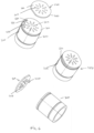
- the closure assembly 100 includes a first filter part 200 having perforations 202 (see Fig. 6 ) formed therein, arranged to be located in the fill port 100 extending across the flow channel 102 between the first and second ends 103, 104 of the fill port 100.
- the assembly may make use of the filter that will typically be included in a fill port. This is often a mandatory requirement for fill ports to avoid ingress of contaminants via the fill port.
- a filter plate having perforations formed therein is located within the fill port, extending across the flow channel formed between the first and second ends of the fill port. The perforations are sized to prevent debris or contaminants passing through the filter to the second end of the fill port.
- the closure assembly of this disclosure may use this filter as the first filter part 200.
- the closure assembly of this disclosure provides a first filter part 200 comprising a filter plate 201 (see Fig. 6 ) having perforations 202 formed therein, arranged to be located within the fill port 100, extending across the flow channel 102 formed between the first and second ends 103, 104 of the fill port.
- the closure assembly of the disclosure also comprises a second filter part 300 having perforations formed therein (see Fig. 6 ), arranged to be located in the fill port extending across the flow channel between the first and second ends of the fill port, the second filter part 300 being rotatable (about the fill port axis A extending in the fluid flow direction) relative to the first filter part (200), and wherein, as best seen in Figs.
- the perforations 202 of the first filter part 200 and the perforations 302 of the second filter part 300 are arranged such that in a first position of rotation of the second filter part relative to the first filter part, the perforations of the second filter part are aligned with the perforations of the first filter part to permit fluid flow through the aligned perforations, and in a second position of rotation of the second filter part relative to the first filter part, the perforations of the second filter part are out of alignment with the perforations of the first filter part such that the second filter part prevents the flow of fluid past the first and second filter parts.
- the closure assembly can be configured with means for applying rotation to the second filter part. This may be implemented (as described further below) such that application of an external force to the second filter part, e.g. an axial force such as may be provided when a hose or connected is attached to the first end of the fill port causes the second filter part to rotate, relative to the first filter part, to the second position.
- the assembly may also be configured such that the second filter is biased to return to the first position when such force is removed.
- the closure assembly includes a spring 500 arranged to hold the second filter part axially relative to the first filter part but to permit the second filter part to rotate relative to the first filter part.
- Figs 3 and 4 show a perspective view and a sectional view of an example of a hydraulic port assembly according to the disclosure.
- a housing 10' is provided through which a port 100 (e.g. a fill port or other hydraulic port) is mounted.
- a second port 101 e.g. an overflow port may also be mounted in the housing 10', but the assembly of the disclosure can also be applied to a hydraulic port assembly which comprises only one port.
- the housing 10' may be in the form of a simple plate for supporting the port(s).
- the first end 103 of the fill port, on one side of the housing 10', is arranged to be attached, in use, to an external connector and/or fill hose.
- the second end 104 of the fill port, on the other side of the housing 10' is arranged to be in fluid communication with the tank or reservoir to be filled.
- a fluid flow channel 102 is defined, along axis A, between the first and the second ends.
- first filter part 200 Located within the fluid flow channel between the first and second ends is a first filter part 200. As will be described further below, this may be in the form of a plate 201 that, when in position in the flow channel, extends across the diameter of the channel. The plate is provided with perforations 202 through which fluid may flow along the flow channel. The perforations are sized to prevent the passage of undesired debris or contaminants past the filter. As mentioned above, in many applications, e.g. in aircraft systems, such filters are mandatory and so the first filter part 200 will already be present. If not, to realise the closure assembly of this disclosure, such a first filter part 200 should be provided to be mounted into the flow channel.
- the second part of the closure assembly is a second filter part 300, which also extends across the flow channel and is provided with perforations 302.
- the second filter part 300 is arranged to be axially aligned with (axially adjacent to) the first filter part in the flow channel.
- the second filter part may also be in the form of a plate or, as shown in this example, in the form of a hollow cylinder having a plate end 301 in which the perforations 302 are formed.
- the second filter part is rotatable (around the axis A) relative to the first filter part so that the locations of the perforations 302 of the second filter part 300 rotate relative to the perforations 202 in the first filter part 200.
- the first and second filter parts 200, 300 together form a filter unit 250 located in the flow channel.
- the closure assembly further includes a spring 500 which is in engagement with the second filter part 300 and is biased to axially hold the second filter part adjacent to (ideally in axial abutment with) the first filter part.
- the filter unit 250 operates as a closure mechanism for the fill port in that the second filter part 200 can rotate relative to the first filter part between a first (open) position in which the perforations 302 in the second filter part align with the perforations 202 in the first filter part, the aligned perforations thus permitting fluid flow through the filter unit, and a second (closed) position where the perforations in the two filter parts are out of alignment.
- the plate 301 of the second filter 302 thus creates a blind bore of the perforations 202 of the first filter element such that fluid is not able to pass through the filter unit 250.
- the rotation of the second filter part may be effected by providing means 320, 324 engaged with the second filter part and extending to the exterior of the port 100 to which a force can be applied to cause rotation of the second filter part.
- the force may be a rotation force, and may be applied manually.
- the means may be configured to receive an axial force and to translate that force into rotation of the second filter part 300. In example of how an axial force can be translated into a rotation of the second filter part is described with particular reference to Figs. 5 to 8 .
- a track, groove or recess 320 is formed in the second filter part 300 e.g. in the cylindrical wall of the second filter part where this is a cylinder.
- the track, groove or recess (hereinafter 'groove' for simplicity) has a first end 321 at a first location and a second end 322 at a second location, the second location being spaced axially and circumferentially from the first location such that the groove defines a part-helix shape.
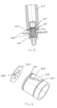
- the means to which a force may be applied further includes a pin 324 extending from outside the port, through an aperture 113 in the wall 115 of the port into engagement with the groove 322.
- the aperture 113 is larger than the diameter of the pin 324 so that the pin can move axially within the aperture when an axial force is applied to the pin.
- the axial force may be applied to the pin manually or, alternatively, by connection of a connector or hose or other fitting to the first end of the port as described further below.
- the close assembly in the first position, is closed. This is typically the default position when no fluid is to be filled through the hydraulic port.
- the spring 500 In the first position, the spring 500 is biased to hold the second filter part in a rotational position, relative to the first filter part, where the perforations of the filter parts are not aligned and so no fluid flows through the filter unit 250.
- the groove 330 is arcuate such that as the secondary filter part rotates, the protrusion 220 travels along the groove 330 between a first end 331 and a second end 332 of the groove.
- the groove 330 is preferably an open groove such that the protrusion comes into contact with the spring 500 as described further below. The force of the spring 500 biases the closure assembly to the closed position.
- the first filter part may be provided with flattened sides 230 for the first filter part to engage in a conventional hydraulic port connector. This prevents rotation of the while filter unit when the connector/fitting is applied to the port.
- Fig. 7 shows the closure assembly in the second, open position. In this position, the second filter element 300 is rotated relative to the first to a position in which its perforations are aligned with the perforations of the first filter element.
- this rotation could be performed by applying an axially downward force on the pin 324 which, by engagement in the groove 322, causes the second filter part to rotate.
- the opening of the closure assembly can be performed in an automatic way when an external connector 600, hose etc. is attached to the first end 101 of the port 100. In aircraft applications, this may be performed e.g. by ground maintenance staff.
- a flange or sleeve 700 is provided around the port, through which the pin 324 extends. The flange is located such that when the connector 600 is attached to the port it exerts an axially downward force on the flange and, thus, on the pin 324 that extends through the flange.
- the groove rides along the pin causing rotation of the second filter element.
- the groove is designed such that when the pin reaches the end 322 of the groove, the perforations in the second filter part are aligned with those of the first filter part to provide a fluid flow passage through the filter unit 250.
- the spring 500 maintains the axial position of the second filter part relative to the first to avoid and leakage between the perforations of the two filter parts.
- O-rings 800 may also be provided between the second filter part and the port to avoid leakage.
- a protrusion 220 extending from the first filter element 200 engages in a groove 330 in the second filter element and contacts, through this groove 330, the spring 500.
- this protrusion 330 therefore compresses the spring 500.
- the first (open) position of the example described can be seen in Fig. 9A and the second (open) position can be seen in Fig. 9B .
- the housing 10' of the present disclosure is much simpler and lighter and less machined than the housing 10 of the known design.
- the housing is usually the most expensive part of the assembly, this is clearly advantageous.
- a reduction in mass, number of parts and manufacturing costs and complexity is important in many fields including the aircraft industry.
- the design of the disclosure avoids the need for flaps and hinges and so reduces the adverse effects of wear of those parts.
- the closures By having the closures internal to the ports and, in some cases, opened automatically on attachment of a hose or connector, the opening and closing function requires much less space and the envelope of the assembly is greatly reduced. Furthermore, the assembly can be easily inspected for damage.
Landscapes
- Engineering & Computer Science (AREA)
- General Engineering & Computer Science (AREA)
- Mechanical Engineering (AREA)
- Aviation & Aerospace Engineering (AREA)
- Joints Allowing Movement (AREA)
- Health & Medical Sciences (AREA)
- Life Sciences & Earth Sciences (AREA)
- Hydrology & Water Resources (AREA)
- Public Health (AREA)
- Water Supply & Treatment (AREA)
Priority Applications (2)
| Application Number | Priority Date | Filing Date | Title |
|---|---|---|---|
| EP23461629.0A EP4495471A1 (fr) | 2023-07-20 | 2023-07-20 | Ensemble de fermeture d'orifice d'eau |
| US18/774,092 US20250027300A1 (en) | 2023-07-20 | 2024-07-16 | Water port closure assembly |
Applications Claiming Priority (1)
| Application Number | Priority Date | Filing Date | Title |
|---|---|---|---|
| EP23461629.0A EP4495471A1 (fr) | 2023-07-20 | 2023-07-20 | Ensemble de fermeture d'orifice d'eau |
Publications (1)
| Publication Number | Publication Date |
|---|---|
| EP4495471A1 true EP4495471A1 (fr) | 2025-01-22 |
Family
ID=87474309
Family Applications (1)
| Application Number | Title | Priority Date | Filing Date |
|---|---|---|---|
| EP23461629.0A Pending EP4495471A1 (fr) | 2023-07-20 | 2023-07-20 | Ensemble de fermeture d'orifice d'eau |
Country Status (2)
| Country | Link |
|---|---|
| US (1) | US20250027300A1 (fr) |
| EP (1) | EP4495471A1 (fr) |
Citations (3)
| Publication number | Priority date | Publication date | Assignee | Title |
|---|---|---|---|---|
| DE1153581B (de) * | 1959-03-14 | 1963-08-29 | Friedrich Gampper K G Metallwa | Absperr- und Drosselvorrichtung fuer Fluessigkeitsleitungen mit einem Drehschieber |
| US6959729B2 (en) * | 2002-04-20 | 2005-11-01 | Kwc Ag | Control cartridge for regulating the water flow at a water outlet of a fitting |
| EP4145034A1 (fr) * | 2021-09-06 | 2023-03-08 | B/E Aerospace, Inc. | Assemblage de capuchon |
Family Cites Families (34)
| Publication number | Priority date | Publication date | Assignee | Title |
|---|---|---|---|---|
| US293240A (en) * | 1884-02-12 | Valve | ||
| US3026899A (en) * | 1960-02-24 | 1962-03-27 | Myron S Mischanski | Valves |
| US3426797A (en) * | 1965-10-20 | 1969-02-11 | Willis Oil Tool Co | Multiple orifice valve |
| US3843172A (en) * | 1973-09-26 | 1974-10-22 | Hoff Stevens | Keg tapping device having improved sealing means |
| US4360040A (en) * | 1980-02-27 | 1982-11-23 | Smith International Inc. | Multiple orifice valves |
| US4395019A (en) * | 1981-04-24 | 1983-07-26 | Mobil Oil Corporation | Seal for wear resistant inserts |
| US4549579A (en) * | 1984-06-22 | 1985-10-29 | American Standard Inc. | Straight-way valve |
| US4554948A (en) * | 1984-06-22 | 1985-11-26 | American Standard Inc. | Straight-way valve |
| US4848403A (en) * | 1988-03-10 | 1989-07-18 | Pilolla Joseph J | Flow-control valve |
| US5088689A (en) * | 1988-10-31 | 1992-02-18 | Automatic Control Components, Inc. | Removable discharge sleeve in a disk valve |
| US5025833A (en) * | 1988-10-31 | 1991-06-25 | Automatic Control Components, Inc. | Disk valve |
| US5063954A (en) * | 1989-10-04 | 1991-11-12 | Automatic Control Components | Multiple orifice valve with reduced operator torque |
| US5025832A (en) * | 1990-09-14 | 1991-06-25 | Taylor Julian S | Multiple orifice rotatable disc in-line restrictor valve |
| GB2380241B (en) * | 2001-07-12 | 2003-08-20 | Huntleigh Technology Plc | Connector |
| DE10135793C1 (de) * | 2001-07-23 | 2003-04-17 | Lucas Automotive Gmbh | Hydraulikfluidbehälter für eine hydraulische Fahrzeugbremsanlage |
| WO2005124218A1 (fr) * | 2004-06-16 | 2005-12-29 | Cntek, Corp. | Raccord rapide pour tuyaux assurant un montage et un demontage faciles |
| DE102004035854B4 (de) * | 2004-07-23 | 2007-11-22 | Airbus Deutschland Gmbh | Adapter zum Kuppeln von zwei Verbindungsleitungen |
| US7726338B2 (en) * | 2007-10-26 | 2010-06-01 | Uponor Innovation Ab | Valve with ceramic discs |
| GB2470609B (en) * | 2009-05-30 | 2013-10-09 | Aker Subsea Ltd | Subsea hydraulic coupler |
| US8776637B2 (en) * | 2012-01-06 | 2014-07-15 | Gm Global Technology Operations, Llc | Hydraulic fluid transfer assembly |
| US10436365B2 (en) * | 2012-04-27 | 2019-10-08 | Leigh Maxwell Remfry | Refueling coupling |
| EP3187764B1 (fr) * | 2015-12-29 | 2019-10-16 | FASTER S.r.l. | Bloc de support pour raccords interchangeables |
| US10871234B2 (en) * | 2018-10-23 | 2020-12-22 | Cameron International Corporation | Low-torque disc for a multiple orifice valve |
| IT201900002529A1 (it) * | 2019-02-21 | 2020-08-21 | Giacomini Spa | Valvola di regolazione e bilanciamento idraulici della portata di fluido |
| DE102019107359A1 (de) * | 2019-03-22 | 2020-09-24 | Airbus Operations Gmbh | Vielzweckanschluss für ein Flugzeugmonument sowie Flugzeugmonument, Flugzeugbereich und Flugzeug mit Vielzweckanschluss |
| US11885438B2 (en) * | 2020-03-30 | 2024-01-30 | Lancaster Flow Automation, Llc | Choke Valve |
| DE102021117773A1 (de) * | 2021-07-09 | 2023-01-12 | Viega Technology Gmbh & Co. Kg | Ventil zur Regulierung eines Durchflusses eines Mediums |
| FR3127542B1 (fr) * | 2021-09-24 | 2023-10-13 | Staubli Sa Ets | Ensemble de connexion et ensemble de refroidissement |
| TWM623783U (zh) * | 2021-11-12 | 2022-02-21 | 志合訊息股份有限公司 | 給水裝置及其水管接頭結構 |
| EP4257857A1 (fr) * | 2022-04-06 | 2023-10-11 | Goodrich Corporation | Ensemble fermeture d'orifice d'eau |
| US12123526B2 (en) * | 2022-09-12 | 2024-10-22 | Avantor Fluid Handling, Llc | Aseptic connect and disconnect coupler |
| EP4398678A1 (fr) * | 2023-01-04 | 2024-07-10 | Goodrich Corporation | Ensemble de chauffage |
| EP4407225B1 (fr) * | 2023-01-26 | 2025-12-10 | B/E Aerospace, Inc. | Ensemble de fermeture d'orifice d'eau |
| EP4406740B1 (fr) * | 2023-01-26 | 2026-04-08 | B/E Aerospace, Inc. | Ensemble orifice de remplissage |
-
2023
- 2023-07-20 EP EP23461629.0A patent/EP4495471A1/fr active Pending
-
2024
- 2024-07-16 US US18/774,092 patent/US20250027300A1/en active Pending
Patent Citations (3)
| Publication number | Priority date | Publication date | Assignee | Title |
|---|---|---|---|---|
| DE1153581B (de) * | 1959-03-14 | 1963-08-29 | Friedrich Gampper K G Metallwa | Absperr- und Drosselvorrichtung fuer Fluessigkeitsleitungen mit einem Drehschieber |
| US6959729B2 (en) * | 2002-04-20 | 2005-11-01 | Kwc Ag | Control cartridge for regulating the water flow at a water outlet of a fitting |
| EP4145034A1 (fr) * | 2021-09-06 | 2023-03-08 | B/E Aerospace, Inc. | Assemblage de capuchon |
Also Published As
| Publication number | Publication date |
|---|---|
| US20250027300A1 (en) | 2025-01-23 |
Similar Documents
| Publication | Publication Date | Title |
|---|---|---|
| US4634098A (en) | Ball Valve | |
| EP1606039B1 (fr) | Filtre multifonction | |
| DE102012018859B4 (de) | Öffnungs- und Schließvorrichtung für einen Kraftstofftank | |
| US20110042604A1 (en) | Device for Connecting a Valve Housing to an Actuator in a Process Valve Acting as a Lift Valve | |
| US3987812A (en) | Adapter valve | |
| JPH03555B2 (fr) | ||
| US12552658B2 (en) | Water port closure assembly | |
| US4690296A (en) | Open flow valve assembly | |
| JP4262833B2 (ja) | 保護ケース入り袋の弁装置 | |
| EP4495471A1 (fr) | Ensemble de fermeture d'orifice d'eau | |
| FR2533658A1 (fr) | Robinet a boisseau et a plusieurs positions | |
| EP0171870A1 (fr) | Robinets de distribution de liquide | |
| US4871303A (en) | Fuel drain safety system for fuel pumps and the like | |
| US20100314570A1 (en) | Rotary gate valve with secondary seal | |
| US12441536B2 (en) | Water port closure assembly | |
| KR100571112B1 (ko) | 통기 밸브 조립체 | |
| CA2262195C (fr) | Vanne de wagon-citerne interne equipee d'un blocage de securite | |
| US6113072A (en) | Access port or drain plug with valve for liquid containers | |
| US12292150B2 (en) | Water port closure assembly | |
| EP1065421B1 (fr) | Unité de commande verrouillable d'un robinet | |
| EP0159799A2 (fr) | Robinet à tournant sphérique | |
| CN116472222B (zh) | 用于飞行器的排放阀及相关方法 | |
| CN111212740A (zh) | 墨盒盖 | |
| EP4641054A1 (fr) | Dispositif de soupape | |
| AU722116B2 (en) | Access port or drain plug with valve for liquid containers |
Legal Events
| Date | Code | Title | Description |
|---|---|---|---|
| PUAI | Public reference made under article 153(3) epc to a published international application that has entered the european phase |
Free format text: ORIGINAL CODE: 0009012 |
|
| STAA | Information on the status of an ep patent application or granted ep patent |
Free format text: STATUS: THE APPLICATION HAS BEEN PUBLISHED |
|
| AK | Designated contracting states |
Kind code of ref document: A1 Designated state(s): AL AT BE BG CH CY CZ DE DK EE ES FI FR GB GR HR HU IE IS IT LI LT LU LV MC ME MK MT NL NO PL PT RO RS SE SI SK SM TR |
|
| STAA | Information on the status of an ep patent application or granted ep patent |
Free format text: STATUS: REQUEST FOR EXAMINATION WAS MADE |
|
| 17P | Request for examination filed |
Effective date: 20250722 |