EP4495513A1 - Appareil de réfrigération avec système de conduit en communication fluidique avec le compartiment de réfrigération et le compartiment de congélation - Google Patents
Appareil de réfrigération avec système de conduit en communication fluidique avec le compartiment de réfrigération et le compartiment de congélation Download PDFInfo
- Publication number
- EP4495513A1 EP4495513A1 EP24189450.0A EP24189450A EP4495513A1 EP 4495513 A1 EP4495513 A1 EP 4495513A1 EP 24189450 A EP24189450 A EP 24189450A EP 4495513 A1 EP4495513 A1 EP 4495513A1
- Authority
- EP
- European Patent Office
- Prior art keywords
- refrigeration
- freezer
- inner liner
- compartment
- aperture
- Prior art date
- Legal status (The legal status is an assumption and is not a legal conclusion. Google has not performed a legal analysis and makes no representation as to the accuracy of the status listed.)
- Withdrawn
Links
Images


Classifications
-
- F—MECHANICAL ENGINEERING; LIGHTING; HEATING; WEAPONS; BLASTING
- F25—REFRIGERATION OR COOLING; COMBINED HEATING AND REFRIGERATION SYSTEMS; HEAT PUMP SYSTEMS; MANUFACTURE OR STORAGE OF ICE; LIQUEFACTION SOLIDIFICATION OF GASES
- F25D—REFRIGERATORS; COLD ROOMS; ICE-BOXES; COOLING OR FREEZING APPARATUS NOT OTHERWISE PROVIDED FOR
- F25D21/00—Defrosting; Preventing frosting; Removing condensed or defrost water
- F25D21/14—Collecting or removing condensed and defrost water; Drip trays
-
- F—MECHANICAL ENGINEERING; LIGHTING; HEATING; WEAPONS; BLASTING
- F25—REFRIGERATION OR COOLING; COMBINED HEATING AND REFRIGERATION SYSTEMS; HEAT PUMP SYSTEMS; MANUFACTURE OR STORAGE OF ICE; LIQUEFACTION SOLIDIFICATION OF GASES
- F25D—REFRIGERATORS; COLD ROOMS; ICE-BOXES; COOLING OR FREEZING APPARATUS NOT OTHERWISE PROVIDED FOR
- F25D11/00—Self-contained movable devices, e.g. domestic refrigerators
- F25D11/02—Self-contained movable devices, e.g. domestic refrigerators with cooling compartments at different temperatures
-
- F—MECHANICAL ENGINEERING; LIGHTING; HEATING; WEAPONS; BLASTING
- F25—REFRIGERATION OR COOLING; COMBINED HEATING AND REFRIGERATION SYSTEMS; HEAT PUMP SYSTEMS; MANUFACTURE OR STORAGE OF ICE; LIQUEFACTION SOLIDIFICATION OF GASES
- F25D—REFRIGERATORS; COLD ROOMS; ICE-BOXES; COOLING OR FREEZING APPARATUS NOT OTHERWISE PROVIDED FOR
- F25D17/00—Arrangements for circulating cooling fluids; Arrangements for circulating gas, e.g. air, within refrigerated spaces
- F25D17/04—Arrangements for circulating cooling fluids; Arrangements for circulating gas, e.g. air, within refrigerated spaces for circulating air, e.g. by convection
- F25D17/042—Air treating means within refrigerated spaces
- F25D17/047—Pressure equalising devices
-
- F—MECHANICAL ENGINEERING; LIGHTING; HEATING; WEAPONS; BLASTING
- F25—REFRIGERATION OR COOLING; COMBINED HEATING AND REFRIGERATION SYSTEMS; HEAT PUMP SYSTEMS; MANUFACTURE OR STORAGE OF ICE; LIQUEFACTION SOLIDIFICATION OF GASES
- F25D—REFRIGERATORS; COLD ROOMS; ICE-BOXES; COOLING OR FREEZING APPARATUS NOT OTHERWISE PROVIDED FOR
- F25D23/00—General constructional features
- F25D23/06—Walls
- F25D23/065—Details
- F25D23/066—Liners
-
- F—MECHANICAL ENGINEERING; LIGHTING; HEATING; WEAPONS; BLASTING
- F25—REFRIGERATION OR COOLING; COMBINED HEATING AND REFRIGERATION SYSTEMS; HEAT PUMP SYSTEMS; MANUFACTURE OR STORAGE OF ICE; LIQUEFACTION SOLIDIFICATION OF GASES
- F25D—REFRIGERATORS; COLD ROOMS; ICE-BOXES; COOLING OR FREEZING APPARATUS NOT OTHERWISE PROVIDED FOR
- F25D23/00—General constructional features
- F25D23/06—Walls
- F25D23/065—Details
- F25D23/068—Arrangements for circulating fluids through the insulating material
-
- F—MECHANICAL ENGINEERING; LIGHTING; HEATING; WEAPONS; BLASTING
- F25—REFRIGERATION OR COOLING; COMBINED HEATING AND REFRIGERATION SYSTEMS; HEAT PUMP SYSTEMS; MANUFACTURE OR STORAGE OF ICE; LIQUEFACTION SOLIDIFICATION OF GASES
- F25D—REFRIGERATORS; COLD ROOMS; ICE-BOXES; COOLING OR FREEZING APPARATUS NOT OTHERWISE PROVIDED FOR
- F25D2201/00—Insulation
- F25D2201/10—Insulation with respect to heat
- F25D2201/14—Insulation with respect to heat using subatmospheric pressure
-
- F—MECHANICAL ENGINEERING; LIGHTING; HEATING; WEAPONS; BLASTING
- F25—REFRIGERATION OR COOLING; COMBINED HEATING AND REFRIGERATION SYSTEMS; HEAT PUMP SYSTEMS; MANUFACTURE OR STORAGE OF ICE; LIQUEFACTION SOLIDIFICATION OF GASES
- F25D—REFRIGERATORS; COLD ROOMS; ICE-BOXES; COOLING OR FREEZING APPARATUS NOT OTHERWISE PROVIDED FOR
- F25D2321/00—Details or arrangements for defrosting; Preventing frosting; Removing condensed or defrost water, not provided for in other groups of this subclass
- F25D2321/14—Collecting condense or defrost water; Removing condense or defrost water
- F25D2321/146—Collecting condense or defrost water; Removing condense or defrost water characterised by the pipes or pipe connections
Definitions
- the present disclosure generally relates to a refrigeration appliance, and more specifically, to a refrigeration appliance with a conduit system that is in fluid communication with both a refrigeration compartment and a freezer compartment of the refrigeration appliance.
- a refrigeration appliance can include a vacuum insulated structure that defines both a refrigeration compartment and a freezer compartment, and one or more doors allowing selective access to those compartments from an external environment.
- air pressure within the refrigeration compartment can decrease relative to atmospheric pressure, which resists a user attempting to open the doorto the refrigeration compartment.
- the user might have to use a greater pulling force to open the door than the user would like.
- the present disclosure addresses the problem with a conduit system that allows airflow from the freezer compartment to the refrigeration compartment to reduce the pressure differential between the air within the refrigeration compartment and atmospheric air pressure when the user opens the door to the refrigeration compartment.
- a refrigeration appliance comprises: (a) a cabinet comprising (i) a vacuum insulated structure at least partially defining a refrigeration compartment and a freezer compartment and (ii) a conduit system in fluid communication with both the refrigeration compartment and the freezer compartment; (b) a refrigeration door coupled to the cabinet, the refrigeration door manipulable to, from, and between (i) a closed position where the refrigeration door denies access to the refrigeration compartment from an external environment and (ii) an open position where the refrigeration door allows access to the refrigeration compartment from the external environment; and (c) a refrigeration door coupled to the cabinet, the refrigeration door manipulable to, from, and between (i) a closed position where the refrigeration door denies access to the refrigeration compartment from an external environment and (ii) an open position where the refrigeration door allows access to the refrigeration compartment from the external environment.
- a refrigeration appliance comprises: (I) a cabinet comprising (A) vacuum insulated structure comprising (1) a refrigeration inner liner at least partially defining a refrigeration compartment and comprising an aperture, (2) a freezer inner liner at least partially defining a freezer compartment and comprising an aperture, (3) an outer wrapper that at least partially envelopes both the refrigeration inner liner and the freezer inner liner but is separated therefrom by a contiguous spaces, the outer wrapper comprising (a) a first aperture that is aligned with the aperture through the refrigeration inner liner and (b) a second aperture that is aligned with the aperture through the freezer inner liner, (B) a refrigeration evaporator disposed within the refrigeration compartment, (C) a freezer evaporator disposed within the freezer compartment, and (D) a conduit system comprising: (1) a refrigeration conduit comprising (a) a first portion positioned to accept condensate collected from the refrigeration evaporator, (b) a body extending from the first portion, through the aperture of
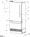
- the terms “upper,” “lower,” “right,” “left,” “rear,” “front,” “vertical,” “horizontal,” and derivatives thereof shall relate to the disclosure as oriented in FIG. 1 .
- the term “front” shall refer to the surface of the element closer to an intended viewer, and the term “rear” shall refer to the surface of the element further from the intended viewer.
- the disclosure may assume various alternative orientations, except where expressly specified to the contrary.
- the specific devices and processes illustrated in the attached drawings, and described in the following specification are simply exemplary embodiments of the inventive concepts defined in the appended claims. Hence, specific dimensions and other physical characteristics relating to the embodiments disclosed herein are not to be considered as limiting, unless the claims expressly state otherwise.
- a refrigeration appliance 10 includes a cabinet 12, a refrigeration door 14, and a freezer door or drawer 16.
- the cabinet 12 includes a vacuum insulated structure 18 that at least partially defines a refrigeration compartment 20 and a freezer compartment 22.
- the refrigeration appliance 10 can maintain an air temperature within the refrigeration compartment 20 above the freezing point of water but less than the room temperature, such as a temperature within a range of from 2 °C to 4 °C.
- the air temperature within the refrigeration compartment 20 thus can prolong shelf-life of a food item 24 disposed within the refrigeration compartment 20.
- the refrigeration appliance 10 can maintain an air temperature within the freezer compartment 22 below the freezing point of water, such as a temperature within a range of from -18 °C to -23 °C.
- the refrigeration appliance 10 can be of the built-in variety, as in the illustrated embodiments, where the cabinet 12 is configured to be recessed behind cabinetry (not illustrated) or of the stand-alone variety. In embodiments where the refrigeration appliance 10 is of the stand-alone variety, refrigeration appliance 10 can include a cover (not illustrated) over the cabinet 12 that is aesthetically pleasing.
- the refrigeration door 14 is coupled to the cabinet 12, such as via one or more hinges 26 that are attached to both the refrigeration door 14 and the cabinet 12.
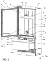
- the refrigeration door 14 is manipulable to, from, and between a closed position 28 (see FIG. 1 ) and an open position 30 (see FIG. 2 ).
- the refrigeration door 14 can include a handle 32 to facilitate a user manipulating the refrigeration door 14 accordingly.
- the closed position 28 the refrigeration door 14 denies access to the refrigeration compartment 20 from an external environment 34.
- the refrigeration door 14 covers an opening 36 into the refrigeration compartment 20 in the closed position 28.
- the refrigeration door 14 allows access to the refrigeration compartment 20 from the external environment 34.
- the refrigeration door 14, in the open position 30, sufficiently reveals the opening 36 for the user to access the refrigeration compartment 20 from the external environment 34.
- the freezer door or drawer 16 is coupled to the cabinet 12 as well.
- the freezer door can be coupled to the cabinet 12 via hinges 26.
- the freezer drawer 16 can be coupled to the cabinet 12 via a track system 38.
- the freezer door or drawer 16 is manipulable to, from, and between a closed position 28 and an open position 30. In the closed position 28, the freezer door, if included, denies access to the freezer compartment 22 from the external environment 34. For example, the freezer door covers an opening 36 that the cabinet 12 forms into the freezer compartment 22.
- a storage compartment 40 of the freezer drawer 16 is disposed within the freezer compartment 22 and the freezer drawer 16 covers the opening 36 into the freezer compartment 22.
- a food item 24 can be disposed within the storage compartment 40 of the freezer drawer 16.
- the freezer door In the open position 30, the freezer door, if included, does allow access through the opening 36 into the freezer compartment 22 from the external environment 34. If instead, as illustrated, the freezer drawer 16 is included, in the open position 30, the storage compartment 40 of the freezer drawer 16 is at least partially withdrawn from the freezer compartment 22 and accessible to the user from the external environment 34.
- the freezer door or drawer 16 can include a handle 42 to assist the user in manipulating the freezer door or drawer 16.
- the vacuum insulated structure 18 includes a refrigeration inner liner 44, a freezer inner liner 46, and an outer wrapper 48.
- the refrigeration inner liner 44 at least partially defines the refrigeration compartment 20.
- the refrigeration inner liner 44 can include a top wall 50, a bottom wall 52, a side wall 54, a side wall 56, and a rear wall 58.
- the top wall 50 and the bottom wall 52 oppose each other.
- the side wall 54 and the side wall 56 oppose each other.
- the rear wall 58 opposes the refrigeration door 14 when the refrigeration door 14 is in the closed position 28.
- the top wall 50, the bottom wall 52, the side walls 54, 56, and the rear wall 58 bound the refrigeration compartment 20.
- the refrigeration inner liner 44 can be made of a plastic material or welded sheet metal, amount other possibilities.
- the freezer inner liner 46 at least partially defines the freezer compartment 22.
- the freezer inner liner 46 can include a top wall 60, a bottom wall 62, a side wall 64, a side wall 66, and a rear wall 68.
- the top wall 60 and the bottom wall 62 oppose each other.
- the side wall 64 and the side wall 66 oppose each other.
- the rear wall 68 opposes the freezer door or drawer 16 when the freezer door or drawer 16 is in the closed position 28.
- the top wall 60, the bottom wall 62, the side walls 64, 66, and the rear wall 68 bound the freezer compartment 22.
- the freezer inner liner 46 can be made of a plastic material or welded sheet metal, amoung other possibilities.
- the refrigeration inner liner 44 is disposed above the freezer inner liner 46.
- the refrigeration inner liner 44 could be disposed below the freezer inner liner 46.
- the refrigeration inner liner 44 and the freezer inner liner 46 could be disposed side-by-side.
- the outer wrapper 48 at least partially envelopes both the refrigeration inner liner 44 and the freezer inner liner 46.
- the outer wrapper 48 includes a top wall 70, a bottom wall 72, a side wall 74, a side wall 76, and a rear wall 78.
- the top wall 70 and the bottom wall 72 oppose each other.
- the side walls 74, 76 oppose each other.
- the top wall 70 is disposed above the top wall 50 of the refrigeration compartment 20.
- the bottom wall 72 is disposed below the bottom wall 52 of the refrigeration compartment 20.
- the side wall 74 of the outer wrapper 48 is disposed laterally outward from the side wall 54 of the refrigeration inner liner 44 and the side wall 64 of the freezer inner liner 46.
- the side wall 76 of the outer wrapper 48 is disposed laterally outward from the side wall 56 of the refrigeration inner liner 44 and the side wall 66 of the freezer inner liner 46.
- the refrigeration inner liner 44 and the freezer inner liner 46 are both disposed elevationally between the top wall 70 and the bottom wall 72 of the outer wrapper 48.
- the refrigeration inner liner 44 and the freezer inner liner 46 are both disposed between the side wall 74 and the side wall 76 of the outer wrapper 48.
- the rear wall 78 of the outer wrapper 48 is disposed rearward of the rear wall 58 of the refrigeration inner liner 44 and the rear wall 68 of the freezer inner liner 46.
- the outer wrapper 48 is separated from both the refrigeration inner liner 44 and the freezer inner liner 46 by a contiguous space 80.
- the contiguous space 80 separates (i) the top wall 70 of the outer wrapper 48 from the top wall 50 of the refrigeration inner liner 44, (ii) the bottom wall 72 of the outer wrapper 48 from the bottom wall 62 of the freezer inner liner 46, (iii) the side wall 74 of the outer wrapper 48 from the side wall 54 of the refrigeration inner liner 44 and the side wall 64 of the freezer inner liner 46, and (iv) the side wall 76 of the outer wrapper 48 from the side wall 56 of the refrigeration inner liner 44 and the side wall 66 of the freezer inner liner 46.
- the contiguous space 80 separates the refrigeration inner liner 44 from the freezer inner liner 46.
- the contiguous space 80 separates the bottom wall 52 of the refrigeration inner liner 44 from the top wall 60 of the freezer inner liner 46.
- the contiguous space 80 of the vacuum insulated cabinet 12 separating the outer wrapper 48, the refrigeration inner liner 44, and the freezer inner liner 46 from each other has an air pressure that is less than atmospheric air pressure.
- the reduced air pressure within the contiguous space 80 is achieved by evacuating air from the contiguous space 80 and sealing the vacuum insulated structure 18.
- the reduced air pressure reduces thermal transfer from the external environment 34 through the vacuum insulated structure 18 and into the refrigeration compartment 20 and the freezer compartment 22 compared to if the air pressure was not reduced.
- the vacuum insulated structure 18 can further include insulation media 82 (e.g., fumed silica) within the contiguous space 80 to further reduce thermal transfer and to help maintain form of the vacuum insulated structure 18.
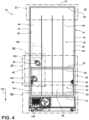
- the cabinet 12 further includes a conduit system 84.
- the conduit system 84 is in fluid communication with both the refrigeration compartment 20 and the freezer compartment 22.
- the conduit system 84 allows air to flow from the freezer compartment 22, through the freezer inner liner 46, through the contiguous space 80, through the outer wrapper 48, alongside the outer wrapper 48, through the contiguous space 80 again, and then through the refrigeration inner liner 44 into the refrigeration compartment 20.
- the conduit system 84 allows air to flow from the refrigeration compartment 20, through the refrigeration inner liner 44, through the contiguous space 80, through the outer wrapper 48, alongside the outer wrapper 48, through the contiguous space 80 again, and then through the freezer inner liner 46 into the freezer compartment 22.
- the refrigeration inner liner 44 comprises an aperture 86 that is aligned with a first aperture 88 of the outer wrapper 48.
- the conduit system 84 extends through the aperture 86 and the first aperture 88 to be in fluid communication with the refrigeration compartment 20.
- the freezer inner liner 46 comprises an aperture 90 that is aligned with a second aperture 92 of the outer wrapper 48.
- the conduit system 84 extends through the aperture 90 and the second aperture 92 to be in fluid communication with the freezer compartment 22.
- “Aligned” here can mean alignment of the aperture 86 and first aperture 88, and of the aperture 90 and the second aperture 92, horizontally forward 94 to rearward 96, but need not be. Any straight-line alignment suffices.
- the vacuum insulated structure 18 further includes a refrigeration passthrough 98.
- the refrigeration passthrough 98 is disposed within the aperture 86 of the refrigeration inner liner 44 and first aperture 88 of the outer wrapper 48.
- An outer surface 100 of the refrigeration passthrough 98 forms an airtight seal against both the refrigeration inner liner 44 and the outer wrapper 48. The airtight seal prevents the air pressure within the contiguous space 80 from equalizing with the atmospheric air pressure.
- the refrigeration passthrough 98 extends through the contiguous space 80 between the aperture 86 and first aperture 88.
- the refrigeration passthrough 98 includes an aperture 102 that may be part of the conduit system 84 to the extent that airflow through the aperture 102 contacts the refrigeration passthrough 98.
- the conduit system 84 thus maintains fluid communication with the refrigeration compartment 20.
- the vacuum insulated structure 18 further includes a freezer passthrough 104.
- the freezer passthrough 104 and the refrigeration passthrough 98 can be identical and thus do not need to be individually illustrated.
- the freezer passthrough 104 is disposed within the aperture 90 of the freezer inner liner 46 and the second aperture 92 of the outer wrapper 48.
- An outer surface 107 of the freezer passthrough 104 forms an airtight seal against both the freezer inner liner 46 and the outer wrapper 48.
- the airtight seal prevents the air pressure within the contiguous space 80 from equalizing with the atmospheric air pressure.
- the freezer passthrough 104 extends through the contiguous space 80 between the aperture 90 and the second aperture 29.
- the freezer passthrough 104 includes an aperture 108 that may be part of the conduit system 84 to the extent that airflow through the aperture 108 contacts the freezer passthrough 104.
- the conduit system 84 thus maintains fluid communication with the freezer compartment 22.
- the conduit system 84 includes a tube 110.
- the tube 110 has a first end 103 and a second end 105.
- the first end 103 can terminate within the aperture 102 of the refrigeration passthrough 98, as illustrated, or proximate the refrigeration passthrough 98 within the refrigeration compartment 20.
- the second end 105 can terminate within the aperture 108 of the freezer passthrough 104, as illustrated, or proximate the freezer passthrough 104 within the freezer compartment 22.
- air flows (i) from the refrigeration compartment 20 into the first end 103 of the tube 110 (either directly or via the aperture 102 through the refrigeration passthrough), (ii) from the first end 103 of the tube 110 toward the second end 105 of the tube 110, and (iii) from the second end 105 of the tube 110 into the freezer compartment 22 (either directly or via the aperture 108 of the freezer passthrough 104).
- the user pulling the freezer door or drawer 16 to the open position 30 pulls air from the refrigeration compartment 20 toward the freezer compartment 22 via the conduit system 84 including the tube 110.
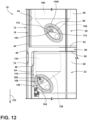
- the cabinet 12 further includes a refrigeration evaporator 106.
- the refrigeration evaporator 106 is disposed within the refrigeration compartment 20. As the refrigeration evaporator 106 is utilized for a refrigeration cycle to withdraw heat from the refrigeration compartment 20, water condenses upon the refrigeration evaporator 106. The condensed water falls from the refrigeration evaporator 106 because of the force of gravity. The water can be collected with the incorporation of a funnel 109 disposed under the refrigeration evaporator 106.
- the conduit system 84 can include a refrigeration conduit 110A positioned to direct the condensate so collected from the refrigeration evaporator 106 to outside of the refrigeration compartment 20. More particularly, in embodiments, such as those illustrated, the refrigeration conduit 110A includes a first portion 112, a second portion 114, and a body 116 disposed between the first portion 112 and the second portion 114. The first portion 112 of the refrigeration conduit 110A is positioned to accept condensate collected from the refrigeration evaporator 106. For example, the first portion 112 can be fluidly coupled to the funnel 109 elevationally below the refrigeration evaporator 106.
- the body 116 of the refrigeration conduit 110A extends from the first portion 112, through the aperture 86 of the refrigeration inner liner 44, through the contiguous space 80 between the refrigeration inner liner 44 and the outer wrapper 48, and through the first aperture 88 of the outer wrapper 48.
- the second portion 114 is disposed external to an outer surface 118 of the outer wrapper 48.
- the second portion 114 can be disposed rearward 96 of the outer wrapper 48 or beneath the outer wrapper 48, among other options.
- the refrigeration conduit 110A extends through the refrigeration passthrough 98.
- the refrigeration passthrough 98 can include an aperture 120 for the refrigeration conduit 110A.
- the first portion 112 of the refrigeration conduit 110A can accept the condensate collected from the refrigeration evaporator 106 within the aperture 120 of the refrigeration passthrough 98 or proximate the refrigeration passthrough 98 within the refrigeration compartment 20.
- the body 116 of the refrigeration conduit 110A then extends away from the first portion 112 within the refrigeration passthrough 98, such as rearward 96.
- the body 116 extends along the outer wrapper 48 external to the outer surface 118 thereof, such as downward 122, so that the force of gravity causes the condensate to flow downward 122 toward the second portion 114.
- the second portion 114 can be disposed elevationally below the first portion 112.
- the cabinet 12 further includes a freezer evaporator 124.
- the freezer evaporator 124 is disposed within the freezer compartment 22.
- water condenses upon the freezer evaporator 124.
- the condensed water falls from the freezer evaporator 124 because of the force of gravity.
- the water can be collected with the incorporation of a funnel 126 disposed under the freezer evaporator 124.
- the refrigeration appliance 10 can further include a defrosting mechanism (e.g., a defrost heater, not illustrated) to facilitate melting of condensate that has frozen upon the freezer evaporator 124.
- the conduit system 84 can include a freezer conduit 128 positioned to direct the condensate so collected from the freezer evaporator 124 to outside of the freezer compartment 22. More particularly, in embodiments, such as those illustrated, the freezer conduit 128 includes a first portion 130, a second portion 132, and a body 134 disposed between the first portion 130 and the second portion 132. The first portion 130 of the freezer conduit 128 is positioned to accept condensate collected from the freezer evaporator 124. For example, the first portion 130 can be fluidly coupled to the funnel 126 elevationally below the freezer evaporator 124.
- the body 134 of the freezer conduit 128 extends from the first portion 130, through the aperture 90 of the freezer inner liner 46, through the contiguous space 80 between the freezer inner liner 46 and the outer wrapper 48, and through the second aperture 92 of the outer wrapper 48.
- the second portion 132 is disposed external to the outer surface 118 of the outer wrapper 48.
- the second portion 132 can be disposed rearward 96 of the outer wrapper 48 or beneath the outer wrapper 48, among other options.
- the freezer conduit 128 extends through the freezer passthrough 104.
- the freezer passthrough 104 can include an aperture 136 for the freezer conduit 128.
- the first portion 130 of the freezer conduit 128 can accept the condensate collected from the freezer evaporator 124 within the aperture 136 of the freezer passthrough 104 or proximate the freezer passthrough 104 within the freezer compartment 22.
- the body 134 of the freezer conduit 128 then extends away the first portion 130 within the freezer passthrough 104, such as rearward 96.
- the body 134 extends along the outer wrapper 48 external to the outer surface 118 thereof, such as downward 122, so that the force of gravity causes the condensate to flow downward 122 toward the second portion 132.
- the second portion 132 can be disposed elevationally below the first portion 130.
- the refrigeration conduit 110A and the freezer conduit 128 of the conduit system 84 are fluidly coupled external to the outer surface 118 of the outer wrapper 48.
- the conduit system 84 can include pipe fittings 138 such as an elbow 138a and a tee 138b to fluidly connect the refrigeration conduit 110A and the freezer conduit 128.
- the refrigeration conduit 110A and the freezer conduit 128 become fluidly coupled elevationally below the second aperture 92 of the outer wrapper 48.
- the conduit system 84 further includes a drain conduit 140.
- the drain conduit 140 is fluidly coupled to both the refrigeration conduit 110A and the freezer conduit 128.
- the drain conduit 140 can include a first end 142 that is fluidly coupled to the tee, which places the first end 142 of the drain conduit 140 in fluid communication with both the second portion 132 of the freezer conduit 128 and the second portion 114 of the refrigeration conduit 110A.
- the cabinet 12 further includes a drain pan 144.
- the conduit system 84 is further in fluid communication with the drain pan 144.
- the drain conduit 140 can include a second end 146 in fluid communication with the drain pan 144.
- the drain pan 144 can be elevationally below the conduit system 84, and the second end 146 of the drain conduit 140 disposed elevationally below the first end 142 of the drain conduit 140, so that condensate flows from the conduit system 84 into the drain pan 144.
- the drain pan 144 can be disposed within a machine room 148 of the cabinet 12, along with refrigeration cycle components such as a compressor 150.
- the vacuum insulated structure 18 can be disposed above the machine room 148 and thus the drain pan 144.
- the conduit system 84 can terminate within the machine room 148 with the second end 146 of the drain conduit 140 be disposed elevationally above the drain pan 144. Condensate thus flows out of the second end 146 of the drain conduit 140 and into the drain pan 144.
- air flows (i) from the freezer compartment 22 and into the first portion 130 of the freezer conduit 128, (ii) from the first portion 130 of the freezer conduit 128 toward the second portion 132 of the freezer conduit 128, (iii) from the second portion 132 of the freezer conduit 128 to the second portion 114 of the refrigeration conduit 110A, (iv) from the second portion 114 of the refrigeration conduit 110A to the first portion 112 of the refrigeration conduit 110A, and (v) from the first portion 112 of the refrigeration conduit 110A into the refrigeration compartment 20.
- air flows (i) from the external environment 34 into the second end 146 of the drain conduit 140, (ii) from the second end 146 of the drain conduit 140 toward first end 142 of the drain conduit 140, (iii) from the first end 142 of the drain conduit 140 to the second end 105 of the refrigeration conduit 110A, (iv) from the second end 105 of the refrigeration conduit 110A towards the first end 103 of the refrigeration conduit 110A, and (v) from the second end 105 of the refrigeration conduit 110A and into the refrigeration compartment 20.
- air flows (i) from the refrigeration compartment 20 and into the first portion 112 of the refrigeration conduit 110A, (ii) from the first portion 112 of the refrigeration conduit 110A toward the second portion 114 of the refrigeration conduit 110A, (iii) from the second portion 114 of the refrigeration conduit 110A to the second portion 132 of the freezer conduit 128, (iv) from the second portion 132 of the freezer conduit 128 to the first portion 130 of the freezer conduit 128, and (v) from the first portion 130 of the freezer conduit 128 into the freezer compartment 22.
- air flows (i) from the external environment 34 into the second end 146 of the drain conduit 140, (ii) from the second end 146 of the drain conduit 140 toward first end 142 of the drain conduit 140, (iii) from the first end 142 of the drain conduit 140 to the second end 105 of the freezer conduit 128, (iv) from the second end 105 of the freezer conduit 128 towards the first end 103 of the freezer conduit 128, and (v) from the second end 105 of the freezer conduit 128 and into the freezer compartment 22.
- the conduit system 84 can include the tube 110, but not the refrigeration conduit 110A fluidly coupled to the freezer conduit 128, to direct airflow from the freezer compartment 22 into the refrigeration compartment 20 as the refrigeration door 14 is moved to the open position 30 or from the refrigeration compartment 20 into the freezer compartment 22 as the freezer door or drawer 16 is moved to the open position 30.
- the conduit system 84 can include the refrigeration conduit 110A fluidly coupled to the freezer conduit 128, but not the tube 110, to direct airflow from the freezer compartment 22 into the refrigeration compartment 20 as the refrigeration door 14 is moved to the open position 30 or from the refrigeration compartment 20 into the freezer compartment 22 as the freezer door or drawer 16 is moved to the open position 30.
- the conduit system 84 can include both the tube 110 and the refrigeration conduit 110A fluidly coupled to the freezer conduit 128 to direct airflow from the freezer compartment 22 into the refrigeration compartment 20 as the refrigeration door 14 is moved to the open position 30 or from the refrigeration compartment 20 into the freezer compartment 22 as the freezer door or drawer 16 is moved to the open position 30.
- the drawings include both embodiments simultaneously for ease of description, but the refrigeration appliance 10 could include just one of the embodiments to the exclusion of the other. Note that in the instances where the refrigeration appliance 10 includes the tube 110 but not the refrigeration conduit 110A fluidly coupled to the freezer conduit 128, the refrigeration appliance 10 can additionally include the refrigeration conduit 110A and the freezer conduit 128 in separate fluid communication with the drain pan 144.
- Incorporating the conduit system 84 with the refrigeration conduit 110A fluidly coupled to the freezer conduit 128 but not the tube 110 may be advantageous to decrease the number of apertures (such as eliminating apertures 102, 108) through the refrigeration passthrough 98 and the freezer passthrough 104, because the apertures 136, 120 for the freezer conduit 128 and the refrigeration conduit 110A, respectively, may need to be included anyway to drain condensate from freezer evaporator 124 and the refrigeration evaporator 106.
- the embodiments of the conduit system 84 of the present disclosure address the problem described in the Background, because, as the user pulls the refrigeration door 14 toward the open position 30, the conduit system 84 allows airflow from the freezer compartment 22 to the refrigeration compartment 20. The additional airflow into the refrigeration compartment 20 lessens the air pressure differential between the air within the refrigeration compartment 20 and atmospheric air pressure. The user thus uses a lesser pulling force to move the refrigeration door 14 to the open position 30 compared to if the refrigeration appliance 10 did not include such a conduit system 84.
- the conduit system 84 may reduce moisture imbalance between the refrigeration compartment 20 and the freezer compartment 22 compared to if no conduit system 84 was included to allow air to flow between the refrigeration compartment 20 and the freezer compartment 22.
- the reduction in the moisture imbalance could mean a reduced relative humidity within the refrigeration compartment 20.
- the reduced relative humidity reduces the volume of insulation needed to cover refrigeration cycle lines within the refrigeration compartment 20, which leads to increased capacity for the refrigeration compartment 20 to hold food items 24.
- a refrigeration appliance comprises: (a) a cabinet comprising (i) a vacuum insulated structure at least partially defining a refrigeration compartment and a freezer compartment and (ii) a conduit system in fluid communication with both the refrigeration compartment and the freezer compartment; (b) a refrigeration door coupled to the cabinet, the refrigeration door manipulable to, from, and between (i) a closed position where the refrigeration door denies access to the refrigeration compartment from an external environment and (ii) an open position where the refrigeration door allows access to the refrigeration compartment from the external environment; and (c) a freezer door or drawer coupled to the cabinet, the freezer door or drawer manipulable to, from, and between (i) a closed position where the freezer door or drawer denies access to the freezer compartment from the external environment and (ii) an open position where the freezer door or drawer allows access to the freezer compartment from the external environment.
- the refrigeration appliance of the first aspect comprises (i) a refrigeration inner liner at least partially defining the refrigeration compartment, (ii) a freezer inner liner at least partially defining the freezer compartment, and (iii) an outer wrapper that at least partially envelopes both the refrigeration inner liner and the freezer inner liner but is separated therefrom by a contiguous space; and (b) the conduit system allows air to flow from the freezer compartment, through the freezer inner liner, through the contiguous space, through the outer wrapper, alongside the outer wrapper, through the contiguous space again, and then through the refrigeration inner liner into the refrigeration compartment.
- the refrigeration appliance of the second aspect is presented, wherein the refrigeration inner liner is disposed above the freezer inner liner.
- the refrigeration appliance of any one of the second through third aspects is presented, wherein the contiguous space further separates the refrigeration inner liner from the freezer inner liner.
- the refrigeration appliance of any one of the second through fourth aspects is presented, wherein (i) the refrigeration inner liner comprises an aperture that is aligned with an aperture of outer wrapper, and (ii) the conduit system extends through the apertures of the refrigeration inner liner and the outer wrapper that are aligned.
- the refrigeration appliance of the fifth aspect is presented, wherein (i) the vacuum insulated structure further comprises a refrigeration passthrough disposed within the apertures of the refrigeration inner liner and the outer wrapper, forms an air-tight seal against the refrigeration inner liner and the outer wrapper, and extends through the contiguous space between the apertures; and (ii) the conduit system comprises an aperture that extends through the refrigeration passthrough.
- the refrigeration appliance of any one of the second through sixth aspects is presented, wherein (i) the freezer inner liner comprises an aperture that is aligned with an aperture of outer wrapper, and (ii) the conduit system extends through the apertures of the freezer inner liner and the outer wrapper that are aligned.
- the refrigeration appliance of the seventh aspect is presented, wherein (i) the vacuum insulated structure further comprises a freezer passthrough disposed within the apertures of the freezer inner liner and the outer wrapper, forms an air-tight seal against the freezer inner liner and the outer wrapper, and extends through the contiguous space between the apertures; and (ii) the conduit system comprises an aperture that extends through the freezer passthrough.
- the refrigeration appliance of the second aspect is presented, wherein (1) the refrigeration inner liner comprises an aperture that is aligned with a first aperture of the outer wrapper; (2) the vacuum insulated structure further comprises a refrigeration passthrough disposed within the aperture of the refrigeration inner liner and the first aperture of the outer wrapper, forms an air-tight seal against the refrigeration inner liner and the outer wrapper, and extends through the contiguous space; (3) the freezer inner liner comprises an aperture that is aligned with a second aperture of outer wrapper; (4) the vacuum insulated structure further comprises a freezer passthrough disposed within the aperture of the freezer inner liner and the second aperture of the outer wrapper, forms an air-tight seal against the freezer inner liner and the outer wrapper, and extends through the contiguous space; and (5) the conduit system comprises (a) an aperture of the refrigeration passthrough, (b) an aperture of the freezer passthrough, and (c) a tube comprising (i) a first end that terminates within the aperture of the refrigeration passthrough
- the refrigeration appliance of any one of the first through ninth aspects is presented, wherein (i) the cabinet further comprises a refrigeration evaporator disposed within the refrigeration compartment; and (ii) the conduit system comprises a refrigeration conduit positioned to direct condensate collected from the refrigeration evaporator from the refrigeration compartment to outside of the refrigeration compartment.
- the refrigeration appliance of any one of the first through tenth aspects is presented, wherein (i) the cabinet further comprises a freezer evaporator disposed within the freezer compartment; and (ii) the conduit system comprises a freezer conduit positioned to direct condensate collected from the freezer evaporator from the refrigeration compartment to outside the freezer compartment.
- the refrigeration appliance of any one of the first through eleventh aspects is presented, wherein (i) the cabinet further comprises a drain pan, and (ii) the conduit system is in further fluid communication with the drain pan.
- the refrigeration appliance of any one of the first through twelfth aspects is presented, wherein (i) the cabinet further comprises a machine room, and (ii) the conduit system terminates within the machine room.
- the refrigeration appliance of the thirteenth aspect is presented, wherein the vacuum insulated structure is disposed above the machine room.
- a refrigeration appliance comprises: (I) a cabinet comprising (A) vacuum insulated structure comprising (1) a refrigeration inner liner at least partially defining a refrigeration compartment and comprising an aperture, (2) a freezer inner liner at least partially defining a freezer compartment and comprising an aperture, (3) an outer wrapper that at least partially envelopes both the refrigeration inner liner and the freezer inner liner but is separated therefrom by a contiguous space, the outer wrapper comprising (a) a first aperture that is aligned with the aperture through the refrigeration inner liner and (b) a second aperture that is aligned with the aperture through the freezer inner liner, (B) a refrigeration evaporator disposed within the refrigeration compartment, (C) a freezer evaporator disposed within the freezer compartment, and (D) a conduit system comprising: (1) a refrigeration conduit comprising (a) a first portion positioned to accept condensate collected from the refrigeration evaporator, (b) a body extending from the first portion, through
- the refrigeration appliance of the fifteenth aspect further comprises: (a) a refrigeration door coupled to the cabinet, the refrigeration door manipulable to, from, and between (i) a closed position where the refrigeration door denies access to the refrigeration compartment from an external environment and (ii) an open position where the refrigeration door allows access to the refrigeration compartment from the external environment; and (b) a freezer door or drawer coupled to the cabinet, the freezer door or drawer manipulable to, from, and between (i) a closed position where the freezer door denies access to the freezer compartment from the external environment or a storage compartment of the drawer is disposed within the freezer compartment and (ii) an open position where the freezer door allows access to the freezer compartment from the external environment or the storage compartment of the freezer drawer is at least partially withdrawn from the freezer compartment.
- the refrigeration appliance of the sixteenth aspect is presented, wherein as the refrigeration door is manipulated from the closed position to the open position, air flows (i) from the freezer compartment and into the freezer conduit, (ii) from the freezer conduit and into the refrigeration conduit, and (iii) from the refrigeration conduit and into the refrigeration compartment.
- the refrigeration appliance of any one of the fifteenth through seventeenth aspects is presented, wherein (a) the vacuum insulated structure further comprises a refrigeration passthrough within the aperture of the refrigeration inner liner and the first aperture of the outer wrapper, the refrigeration passthrough forming an air-tight seal against the refrigeration inner liner and the outer wrapper and extending through the space between the refrigeration inner liner and the outer wrapper; (b) the body of the refrigeration conduit extends through the refrigeration passthrough; (c) the vacuum insulated structure further comprises a freezer passthrough within the aperture of the freezer inner liner and the second aperture of the outer wrapper, the freezer passthrough forming an air-tight seal against the freezer inner liner and the outer wrapper and extending through the space between the freezer inner liner and the outer wrapper; and (d) the body of the freezer conduit extends through the freezer passthrough.
- the refrigeration appliance of any one of the fifteenth through eighteenth aspects is presented, wherein (i) the refrigeration inner liner is disposed above the freezer liner, and (ii) the refrigeration conduit and the freezer conduit become fluidly coupled elevationally below the second aperture of the outer wrapper.
- the refrigeration appliance of any one of the fifteenth through nineteenth aspects is presented, wherein (i) the conduit system further includes a drain conduit comprising (i) a first end fluidly coupled to the refrigeration conduit and the freezer conduit and (ii) a second end in fluid communication with a drain pan.
- the term "coupled” in all of its forms, couple, coupling, coupled, etc. generally means the joining of two components (electrical or mechanical) directly or indirectly to one another. Such joining may be stationary in nature or movable in nature. Such joining may be achieved with the two components (electrical or mechanical) and any additional intermediate members being integrally formed as a single unitary body with one another or with the two components. Such joining may be permanent in nature or may be removable or releasable in nature unless otherwise stated.
- elements shown as integrally formed may be constructed of multiple parts or elements shown as multiple parts may be integrally formed, the operation of the interfaces may be reversed or otherwise varied, the length or width of the structures and/or members or connector or other elements of the system may be varied, the nature or number of adjustment positions provided between the elements may be varied.
- the elements and/or assemblies of the system may be constructed from any of a wide variety of materials that provide sufficient strength or durability, in any of a wide variety of colors, textures, and combinations. Accordingly, all such modifications are intended to be included within the scope of the present innovations. Other substitutions, modifications, changes, and omissions may be made in the design, operating conditions, and arrangement of the desired and other exemplary embodiments without departing from the spirit of the present innovations.
Landscapes
- Engineering & Computer Science (AREA)
- Chemical & Material Sciences (AREA)
- Combustion & Propulsion (AREA)
- Physics & Mathematics (AREA)
- Mechanical Engineering (AREA)
- Thermal Sciences (AREA)
- General Engineering & Computer Science (AREA)
- Devices That Are Associated With Refrigeration Equipment (AREA)
Applications Claiming Priority (1)
| Application Number | Priority Date | Filing Date | Title |
|---|---|---|---|
| US18/224,286 US20250027703A1 (en) | 2023-07-20 | 2023-07-20 | Refrigeration appliance with conduit system in fluid communication with both refrigeration compartment and freezer compartment |
Publications (1)
| Publication Number | Publication Date |
|---|---|
| EP4495513A1 true EP4495513A1 (fr) | 2025-01-22 |
Family
ID=91959205
Family Applications (1)
| Application Number | Title | Priority Date | Filing Date |
|---|---|---|---|
| EP24189450.0A Withdrawn EP4495513A1 (fr) | 2023-07-20 | 2024-07-18 | Appareil de réfrigération avec système de conduit en communication fluidique avec le compartiment de réfrigération et le compartiment de congélation |
Country Status (3)
| Country | Link |
|---|---|
| US (1) | US20250027703A1 (fr) |
| EP (1) | EP4495513A1 (fr) |
| CN (1) | CN119334042A (fr) |
Citations (5)
| Publication number | Priority date | Publication date | Assignee | Title |
|---|---|---|---|---|
| JPH01136875U (fr) * | 1988-03-14 | 1989-09-19 | ||
| KR0153297B1 (ko) * | 1996-06-25 | 1999-01-15 | 김광호 | 냉장고 |
| WO2009132940A2 (fr) * | 2008-04-29 | 2009-11-05 | BSH Bosch und Siemens Hausgeräte GmbH | Réfrigérateur |
| CN203177570U (zh) * | 2013-03-19 | 2013-09-04 | 合肥荣事达三洋电器股份有限公司 | 冰箱箱体 |
| CN204494950U (zh) * | 2015-02-13 | 2015-07-22 | 合肥美菱股份有限公司 | 一种直冷冰箱冷冻室的压力平衡结构 |
Family Cites Families (1)
| Publication number | Priority date | Publication date | Assignee | Title |
|---|---|---|---|---|
| JP5872143B2 (ja) * | 2010-07-28 | 2016-03-01 | 株式会社東芝 | 冷蔵庫 |
-
2023
- 2023-07-20 US US18/224,286 patent/US20250027703A1/en not_active Abandoned
-
2024
- 2024-07-16 CN CN202410950258.1A patent/CN119334042A/zh active Pending
- 2024-07-18 EP EP24189450.0A patent/EP4495513A1/fr not_active Withdrawn
Patent Citations (5)
| Publication number | Priority date | Publication date | Assignee | Title |
|---|---|---|---|---|
| JPH01136875U (fr) * | 1988-03-14 | 1989-09-19 | ||
| KR0153297B1 (ko) * | 1996-06-25 | 1999-01-15 | 김광호 | 냉장고 |
| WO2009132940A2 (fr) * | 2008-04-29 | 2009-11-05 | BSH Bosch und Siemens Hausgeräte GmbH | Réfrigérateur |
| CN203177570U (zh) * | 2013-03-19 | 2013-09-04 | 合肥荣事达三洋电器股份有限公司 | 冰箱箱体 |
| CN204494950U (zh) * | 2015-02-13 | 2015-07-22 | 合肥美菱股份有限公司 | 一种直冷冰箱冷冻室的压力平衡结构 |
Also Published As
| Publication number | Publication date |
|---|---|
| US20250027703A1 (en) | 2025-01-23 |
| CN119334042A (zh) | 2025-01-21 |
Similar Documents
| Publication | Publication Date | Title |
|---|---|---|
| US9885516B2 (en) | Vacuum insulated door structure and method for the creation thereof | |
| CN106440605B (zh) | 冰箱 | |
| US8429926B2 (en) | Ice storage bin and icemaker apparatus for refrigerator | |
| US20190056165A1 (en) | Refrigerator | |
| CN105444494A (zh) | 冰箱 | |
| KR20100105267A (ko) | 냉장고 | |
| US10767919B2 (en) | Method for ensuring reliable core material fill around the pass throughs in a vacuum insulated structure | |
| US10605516B2 (en) | Refrigerator appliance | |
| JP6061808B2 (ja) | 冷蔵庫 | |
| US11994322B2 (en) | Refrigerator | |
| EP4495513A1 (fr) | Appareil de réfrigération avec système de conduit en communication fluidique avec le compartiment de réfrigération et le compartiment de congélation | |
| JP2021076296A (ja) | 冷蔵庫 | |
| US20250044016A1 (en) | Support system for a vacuum insulated panel | |
| EP4474739A1 (fr) | Appareil frigorifique doté d'une conduite de réfrigérant et d'une conduite d'eau s'étendant à travers un passage commun d'une structure isolée sous vide | |
| CN213514585U (zh) | 冰箱及其玻璃门 | |
| JPH03233281A (ja) | 冷蔵庫 | |
| CN102261782B (zh) | 制冷器具 | |
| CN102261783B (zh) | 制冷器具 | |
| JP2902961B2 (ja) | 低温貯蔵庫 | |
| US12449182B2 (en) | Refrigeration appliance including a refrigerant line and water line extending through common pass-through of a vacuum-insulated structure | |
| EP2778578B1 (fr) | Structure de porte isolée sous vide et procédé de création associé | |
| JP6919008B2 (ja) | 冷蔵庫 | |
| CN214950043U (zh) | 冰箱 | |
| CN209783082U (zh) | 家用制冷器具 | |
| CN114719527B (zh) | 一种冰箱 |
Legal Events
| Date | Code | Title | Description |
|---|---|---|---|
| PUAI | Public reference made under article 153(3) epc to a published international application that has entered the european phase |
Free format text: ORIGINAL CODE: 0009012 |
|
| STAA | Information on the status of an ep patent application or granted ep patent |
Free format text: STATUS: THE APPLICATION HAS BEEN PUBLISHED |
|
| AK | Designated contracting states |
Kind code of ref document: A1 Designated state(s): AL AT BE BG CH CY CZ DE DK EE ES FI FR GB GR HR HU IE IS IT LI LT LU LV MC ME MK MT NL NO PL PT RO RS SE SI SK SM TR |
|
| STAA | Information on the status of an ep patent application or granted ep patent |
Free format text: STATUS: THE APPLICATION HAS BEEN WITHDRAWN |
|
| 18W | Application withdrawn |
Effective date: 20250409 |