EP4495521A2 - Procédé de prérefroidissement d'hydrogène pour liquéfaction avec de l'azote liquide de complément - Google Patents
Procédé de prérefroidissement d'hydrogène pour liquéfaction avec de l'azote liquide de complément Download PDFInfo
- Publication number
- EP4495521A2 EP4495521A2 EP24210930.4A EP24210930A EP4495521A2 EP 4495521 A2 EP4495521 A2 EP 4495521A2 EP 24210930 A EP24210930 A EP 24210930A EP 4495521 A2 EP4495521 A2 EP 4495521A2
- Authority
- EP
- European Patent Office
- Prior art keywords
- hydrogen
- unit
- liquefaction
- stream
- air separation
- Prior art date
- Legal status (The legal status is an assumption and is not a legal conclusion. Google has not performed a legal analysis and makes no representation as to the accuracy of the status listed.)
- Granted
Links
Images


Classifications
-
- F—MECHANICAL ENGINEERING; LIGHTING; HEATING; WEAPONS; BLASTING
- F25—REFRIGERATION OR COOLING; COMBINED HEATING AND REFRIGERATION SYSTEMS; HEAT PUMP SYSTEMS; MANUFACTURE OR STORAGE OF ICE; LIQUEFACTION SOLIDIFICATION OF GASES
- F25J—LIQUEFACTION, SOLIDIFICATION OR SEPARATION OF GASES OR GASEOUS OR LIQUEFIED GASEOUS MIXTURES BY PRESSURE AND COLD TREATMENT OR BY BRINGING THEM INTO THE SUPERCRITICAL STATE
- F25J1/00—Processes or apparatus for liquefying or solidifying gases or gaseous mixtures
- F25J1/0002—Processes or apparatus for liquefying or solidifying gases or gaseous mixtures characterised by the fluid to be liquefied
- F25J1/0005—Light or noble gases
- F25J1/001—Hydrogen
-
- F—MECHANICAL ENGINEERING; LIGHTING; HEATING; WEAPONS; BLASTING
- F25—REFRIGERATION OR COOLING; COMBINED HEATING AND REFRIGERATION SYSTEMS; HEAT PUMP SYSTEMS; MANUFACTURE OR STORAGE OF ICE; LIQUEFACTION SOLIDIFICATION OF GASES
- F25J—LIQUEFACTION, SOLIDIFICATION OR SEPARATION OF GASES OR GASEOUS OR LIQUEFIED GASEOUS MIXTURES BY PRESSURE AND COLD TREATMENT OR BY BRINGING THEM INTO THE SUPERCRITICAL STATE
- F25J1/00—Processes or apparatus for liquefying or solidifying gases or gaseous mixtures
- F25J1/003—Processes or apparatus for liquefying or solidifying gases or gaseous mixtures characterised by the kind of cold generation within the liquefaction unit for compensating heat leaks and liquid production
- F25J1/0047—Processes or apparatus for liquefying or solidifying gases or gaseous mixtures characterised by the kind of cold generation within the liquefaction unit for compensating heat leaks and liquid production using an "external" refrigerant stream in a closed vapor compression cycle
- F25J1/005—Processes or apparatus for liquefying or solidifying gases or gaseous mixtures characterised by the kind of cold generation within the liquefaction unit for compensating heat leaks and liquid production using an "external" refrigerant stream in a closed vapor compression cycle by expansion of a gaseous refrigerant stream with extraction of work
-
- F—MECHANICAL ENGINEERING; LIGHTING; HEATING; WEAPONS; BLASTING
- F25—REFRIGERATION OR COOLING; COMBINED HEATING AND REFRIGERATION SYSTEMS; HEAT PUMP SYSTEMS; MANUFACTURE OR STORAGE OF ICE; LIQUEFACTION SOLIDIFICATION OF GASES
- F25J—LIQUEFACTION, SOLIDIFICATION OR SEPARATION OF GASES OR GASEOUS OR LIQUEFIED GASEOUS MIXTURES BY PRESSURE AND COLD TREATMENT OR BY BRINGING THEM INTO THE SUPERCRITICAL STATE
- F25J1/00—Processes or apparatus for liquefying or solidifying gases or gaseous mixtures
- F25J1/006—Processes or apparatus for liquefying or solidifying gases or gaseous mixtures characterised by the refrigerant fluid used
- F25J1/0062—Light or noble gases, mixtures thereof
- F25J1/0065—Helium
-
- F—MECHANICAL ENGINEERING; LIGHTING; HEATING; WEAPONS; BLASTING
- F25—REFRIGERATION OR COOLING; COMBINED HEATING AND REFRIGERATION SYSTEMS; HEAT PUMP SYSTEMS; MANUFACTURE OR STORAGE OF ICE; LIQUEFACTION SOLIDIFICATION OF GASES
- F25J—LIQUEFACTION, SOLIDIFICATION OR SEPARATION OF GASES OR GASEOUS OR LIQUEFIED GASEOUS MIXTURES BY PRESSURE AND COLD TREATMENT OR BY BRINGING THEM INTO THE SUPERCRITICAL STATE
- F25J1/00—Processes or apparatus for liquefying or solidifying gases or gaseous mixtures
- F25J1/006—Processes or apparatus for liquefying or solidifying gases or gaseous mixtures characterised by the refrigerant fluid used
- F25J1/0062—Light or noble gases, mixtures thereof
- F25J1/0067—Hydrogen
-
- F—MECHANICAL ENGINEERING; LIGHTING; HEATING; WEAPONS; BLASTING
- F25—REFRIGERATION OR COOLING; COMBINED HEATING AND REFRIGERATION SYSTEMS; HEAT PUMP SYSTEMS; MANUFACTURE OR STORAGE OF ICE; LIQUEFACTION SOLIDIFICATION OF GASES
- F25J—LIQUEFACTION, SOLIDIFICATION OR SEPARATION OF GASES OR GASEOUS OR LIQUEFIED GASEOUS MIXTURES BY PRESSURE AND COLD TREATMENT OR BY BRINGING THEM INTO THE SUPERCRITICAL STATE
- F25J1/00—Processes or apparatus for liquefying or solidifying gases or gaseous mixtures
- F25J1/006—Processes or apparatus for liquefying or solidifying gases or gaseous mixtures characterised by the refrigerant fluid used
- F25J1/007—Primary atmospheric gases, mixtures thereof
- F25J1/0072—Nitrogen
-
- F—MECHANICAL ENGINEERING; LIGHTING; HEATING; WEAPONS; BLASTING
- F25—REFRIGERATION OR COOLING; COMBINED HEATING AND REFRIGERATION SYSTEMS; HEAT PUMP SYSTEMS; MANUFACTURE OR STORAGE OF ICE; LIQUEFACTION SOLIDIFICATION OF GASES
- F25J—LIQUEFACTION, SOLIDIFICATION OR SEPARATION OF GASES OR GASEOUS OR LIQUEFIED GASEOUS MIXTURES BY PRESSURE AND COLD TREATMENT OR BY BRINGING THEM INTO THE SUPERCRITICAL STATE
- F25J1/00—Processes or apparatus for liquefying or solidifying gases or gaseous mixtures
- F25J1/006—Processes or apparatus for liquefying or solidifying gases or gaseous mixtures characterised by the refrigerant fluid used
- F25J1/007—Primary atmospheric gases, mixtures thereof
- F25J1/0077—Argon
-
- F—MECHANICAL ENGINEERING; LIGHTING; HEATING; WEAPONS; BLASTING
- F25—REFRIGERATION OR COOLING; COMBINED HEATING AND REFRIGERATION SYSTEMS; HEAT PUMP SYSTEMS; MANUFACTURE OR STORAGE OF ICE; LIQUEFACTION SOLIDIFICATION OF GASES
- F25J—LIQUEFACTION, SOLIDIFICATION OR SEPARATION OF GASES OR GASEOUS OR LIQUEFIED GASEOUS MIXTURES BY PRESSURE AND COLD TREATMENT OR BY BRINGING THEM INTO THE SUPERCRITICAL STATE
- F25J1/00—Processes or apparatus for liquefying or solidifying gases or gaseous mixtures
- F25J1/006—Processes or apparatus for liquefying or solidifying gases or gaseous mixtures characterised by the refrigerant fluid used
- F25J1/0097—Others, e.g. F-, Cl-, HF-, HClF-, HCl-hydrocarbons etc. or mixtures thereof
-
- F—MECHANICAL ENGINEERING; LIGHTING; HEATING; WEAPONS; BLASTING
- F25—REFRIGERATION OR COOLING; COMBINED HEATING AND REFRIGERATION SYSTEMS; HEAT PUMP SYSTEMS; MANUFACTURE OR STORAGE OF ICE; LIQUEFACTION SOLIDIFICATION OF GASES
- F25J—LIQUEFACTION, SOLIDIFICATION OR SEPARATION OF GASES OR GASEOUS OR LIQUEFIED GASEOUS MIXTURES BY PRESSURE AND COLD TREATMENT OR BY BRINGING THEM INTO THE SUPERCRITICAL STATE
- F25J1/00—Processes or apparatus for liquefying or solidifying gases or gaseous mixtures
- F25J1/02—Processes or apparatus for liquefying or solidifying gases or gaseous mixtures requiring the use of refrigeration, e.g. of helium or hydrogen ; Details and kind of the refrigeration system used; Integration with other units or processes; Controlling aspects of the process
- F25J1/0203—Processes or apparatus for liquefying or solidifying gases or gaseous mixtures requiring the use of refrigeration, e.g. of helium or hydrogen ; Details and kind of the refrigeration system used; Integration with other units or processes; Controlling aspects of the process using a single-component refrigerant [SCR] fluid in a closed vapor compression cycle
- F25J1/0205—Processes or apparatus for liquefying or solidifying gases or gaseous mixtures requiring the use of refrigeration, e.g. of helium or hydrogen ; Details and kind of the refrigeration system used; Integration with other units or processes; Controlling aspects of the process using a single-component refrigerant [SCR] fluid in a closed vapor compression cycle as a dual level SCR refrigeration cascade
-
- F—MECHANICAL ENGINEERING; LIGHTING; HEATING; WEAPONS; BLASTING
- F25—REFRIGERATION OR COOLING; COMBINED HEATING AND REFRIGERATION SYSTEMS; HEAT PUMP SYSTEMS; MANUFACTURE OR STORAGE OF ICE; LIQUEFACTION SOLIDIFICATION OF GASES
- F25J—LIQUEFACTION, SOLIDIFICATION OR SEPARATION OF GASES OR GASEOUS OR LIQUEFIED GASEOUS MIXTURES BY PRESSURE AND COLD TREATMENT OR BY BRINGING THEM INTO THE SUPERCRITICAL STATE
- F25J1/00—Processes or apparatus for liquefying or solidifying gases or gaseous mixtures
- F25J1/02—Processes or apparatus for liquefying or solidifying gases or gaseous mixtures requiring the use of refrigeration, e.g. of helium or hydrogen ; Details and kind of the refrigeration system used; Integration with other units or processes; Controlling aspects of the process
- F25J1/0211—Processes or apparatus for liquefying or solidifying gases or gaseous mixtures requiring the use of refrigeration, e.g. of helium or hydrogen ; Details and kind of the refrigeration system used; Integration with other units or processes; Controlling aspects of the process using a multi-component refrigerant [MCR] fluid in a closed vapor compression cycle
- F25J1/0214—Processes or apparatus for liquefying or solidifying gases or gaseous mixtures requiring the use of refrigeration, e.g. of helium or hydrogen ; Details and kind of the refrigeration system used; Integration with other units or processes; Controlling aspects of the process using a multi-component refrigerant [MCR] fluid in a closed vapor compression cycle as a dual level refrigeration cascade with at least one MCR cycle
- F25J1/0215—Processes or apparatus for liquefying or solidifying gases or gaseous mixtures requiring the use of refrigeration, e.g. of helium or hydrogen ; Details and kind of the refrigeration system used; Integration with other units or processes; Controlling aspects of the process using a multi-component refrigerant [MCR] fluid in a closed vapor compression cycle as a dual level refrigeration cascade with at least one MCR cycle with one SCR cycle
-
- F—MECHANICAL ENGINEERING; LIGHTING; HEATING; WEAPONS; BLASTING
- F25—REFRIGERATION OR COOLING; COMBINED HEATING AND REFRIGERATION SYSTEMS; HEAT PUMP SYSTEMS; MANUFACTURE OR STORAGE OF ICE; LIQUEFACTION SOLIDIFICATION OF GASES
- F25J—LIQUEFACTION, SOLIDIFICATION OR SEPARATION OF GASES OR GASEOUS OR LIQUEFIED GASEOUS MIXTURES BY PRESSURE AND COLD TREATMENT OR BY BRINGING THEM INTO THE SUPERCRITICAL STATE
- F25J1/00—Processes or apparatus for liquefying or solidifying gases or gaseous mixtures
- F25J1/02—Processes or apparatus for liquefying or solidifying gases or gaseous mixtures requiring the use of refrigeration, e.g. of helium or hydrogen ; Details and kind of the refrigeration system used; Integration with other units or processes; Controlling aspects of the process
- F25J1/0221—Processes or apparatus for liquefying or solidifying gases or gaseous mixtures requiring the use of refrigeration, e.g. of helium or hydrogen ; Details and kind of the refrigeration system used; Integration with other units or processes; Controlling aspects of the process using the cold stored in an external cryogenic component in an open refrigeration loop
-
- F—MECHANICAL ENGINEERING; LIGHTING; HEATING; WEAPONS; BLASTING
- F25—REFRIGERATION OR COOLING; COMBINED HEATING AND REFRIGERATION SYSTEMS; HEAT PUMP SYSTEMS; MANUFACTURE OR STORAGE OF ICE; LIQUEFACTION SOLIDIFICATION OF GASES
- F25J—LIQUEFACTION, SOLIDIFICATION OR SEPARATION OF GASES OR GASEOUS OR LIQUEFIED GASEOUS MIXTURES BY PRESSURE AND COLD TREATMENT OR BY BRINGING THEM INTO THE SUPERCRITICAL STATE
- F25J1/00—Processes or apparatus for liquefying or solidifying gases or gaseous mixtures
- F25J1/02—Processes or apparatus for liquefying or solidifying gases or gaseous mixtures requiring the use of refrigeration, e.g. of helium or hydrogen ; Details and kind of the refrigeration system used; Integration with other units or processes; Controlling aspects of the process
- F25J1/0228—Coupling of the liquefaction unit to other units or processes, so-called integrated processes
- F25J1/0234—Integration with a cryogenic air separation unit
-
- F—MECHANICAL ENGINEERING; LIGHTING; HEATING; WEAPONS; BLASTING
- F25—REFRIGERATION OR COOLING; COMBINED HEATING AND REFRIGERATION SYSTEMS; HEAT PUMP SYSTEMS; MANUFACTURE OR STORAGE OF ICE; LIQUEFACTION SOLIDIFICATION OF GASES
- F25J—LIQUEFACTION, SOLIDIFICATION OR SEPARATION OF GASES OR GASEOUS OR LIQUEFIED GASEOUS MIXTURES BY PRESSURE AND COLD TREATMENT OR BY BRINGING THEM INTO THE SUPERCRITICAL STATE
- F25J1/00—Processes or apparatus for liquefying or solidifying gases or gaseous mixtures
- F25J1/02—Processes or apparatus for liquefying or solidifying gases or gaseous mixtures requiring the use of refrigeration, e.g. of helium or hydrogen ; Details and kind of the refrigeration system used; Integration with other units or processes; Controlling aspects of the process
- F25J1/0243—Start-up or control of the process; Details of the apparatus used; Details of the refrigerant compression system used
- F25J1/0244—Operation; Control and regulation; Instrumentation
- F25J1/0245—Different modes, i.e. 'runs', of operation; Process control
-
- F—MECHANICAL ENGINEERING; LIGHTING; HEATING; WEAPONS; BLASTING
- F25—REFRIGERATION OR COOLING; COMBINED HEATING AND REFRIGERATION SYSTEMS; HEAT PUMP SYSTEMS; MANUFACTURE OR STORAGE OF ICE; LIQUEFACTION SOLIDIFICATION OF GASES
- F25J—LIQUEFACTION, SOLIDIFICATION OR SEPARATION OF GASES OR GASEOUS OR LIQUEFIED GASEOUS MIXTURES BY PRESSURE AND COLD TREATMENT OR BY BRINGING THEM INTO THE SUPERCRITICAL STATE
- F25J3/00—Processes or apparatus for separating the constituents of gaseous or liquefied gaseous mixtures involving the use of liquefaction or solidification
- F25J3/02—Processes or apparatus for separating the constituents of gaseous or liquefied gaseous mixtures involving the use of liquefaction or solidification by rectification, i.e. by continuous interchange of heat and material between a vapour stream and a liquid stream
- F25J3/04—Processes or apparatus for separating the constituents of gaseous or liquefied gaseous mixtures involving the use of liquefaction or solidification by rectification, i.e. by continuous interchange of heat and material between a vapour stream and a liquid stream for air
- F25J3/04006—Providing pressurised feed air or process streams within or from the air fractionation unit
- F25J3/04078—Providing pressurised feed air or process streams within or from the air fractionation unit providing pressurized products by liquid compression and vaporisation with cold recovery, i.e. so-called internal compression
- F25J3/0409—Providing pressurised feed air or process streams within or from the air fractionation unit providing pressurized products by liquid compression and vaporisation with cold recovery, i.e. so-called internal compression of oxygen
-
- F—MECHANICAL ENGINEERING; LIGHTING; HEATING; WEAPONS; BLASTING
- F25—REFRIGERATION OR COOLING; COMBINED HEATING AND REFRIGERATION SYSTEMS; HEAT PUMP SYSTEMS; MANUFACTURE OR STORAGE OF ICE; LIQUEFACTION SOLIDIFICATION OF GASES
- F25J—LIQUEFACTION, SOLIDIFICATION OR SEPARATION OF GASES OR GASEOUS OR LIQUEFIED GASEOUS MIXTURES BY PRESSURE AND COLD TREATMENT OR BY BRINGING THEM INTO THE SUPERCRITICAL STATE
- F25J3/00—Processes or apparatus for separating the constituents of gaseous or liquefied gaseous mixtures involving the use of liquefaction or solidification
- F25J3/02—Processes or apparatus for separating the constituents of gaseous or liquefied gaseous mixtures involving the use of liquefaction or solidification by rectification, i.e. by continuous interchange of heat and material between a vapour stream and a liquid stream
- F25J3/04—Processes or apparatus for separating the constituents of gaseous or liquefied gaseous mixtures involving the use of liquefaction or solidification by rectification, i.e. by continuous interchange of heat and material between a vapour stream and a liquid stream for air
- F25J3/04151—Purification and (pre-)cooling of the feed air; recuperative heat-exchange with product streams
- F25J3/04163—Hot end purification of the feed air
- F25J3/04169—Hot end purification of the feed air by adsorption of the impurities
- F25J3/04175—Hot end purification of the feed air by adsorption of the impurities at a pressure of substantially more than the highest pressure column
-
- F—MECHANICAL ENGINEERING; LIGHTING; HEATING; WEAPONS; BLASTING
- F25—REFRIGERATION OR COOLING; COMBINED HEATING AND REFRIGERATION SYSTEMS; HEAT PUMP SYSTEMS; MANUFACTURE OR STORAGE OF ICE; LIQUEFACTION SOLIDIFICATION OF GASES
- F25J—LIQUEFACTION, SOLIDIFICATION OR SEPARATION OF GASES OR GASEOUS OR LIQUEFIED GASEOUS MIXTURES BY PRESSURE AND COLD TREATMENT OR BY BRINGING THEM INTO THE SUPERCRITICAL STATE
- F25J3/00—Processes or apparatus for separating the constituents of gaseous or liquefied gaseous mixtures involving the use of liquefaction or solidification
- F25J3/02—Processes or apparatus for separating the constituents of gaseous or liquefied gaseous mixtures involving the use of liquefaction or solidification by rectification, i.e. by continuous interchange of heat and material between a vapour stream and a liquid stream
- F25J3/04—Processes or apparatus for separating the constituents of gaseous or liquefied gaseous mixtures involving the use of liquefaction or solidification by rectification, i.e. by continuous interchange of heat and material between a vapour stream and a liquid stream for air
- F25J3/04248—Generation of cold for compensating heat leaks or liquid production, e.g. by Joule-Thompson expansion
- F25J3/04284—Generation of cold for compensating heat leaks or liquid production, e.g. by Joule-Thompson expansion using internal refrigeration by open-loop gas work expansion, e.g. of intermediate or oxygen enriched (waste-)streams
- F25J3/0429—Generation of cold for compensating heat leaks or liquid production, e.g. by Joule-Thompson expansion using internal refrigeration by open-loop gas work expansion, e.g. of intermediate or oxygen enriched (waste-)streams of feed air, e.g. used as waste or product air or expanded into an auxiliary column
- F25J3/04296—Claude expansion, i.e. expanded into the main or high pressure column
-
- F—MECHANICAL ENGINEERING; LIGHTING; HEATING; WEAPONS; BLASTING
- F25—REFRIGERATION OR COOLING; COMBINED HEATING AND REFRIGERATION SYSTEMS; HEAT PUMP SYSTEMS; MANUFACTURE OR STORAGE OF ICE; LIQUEFACTION SOLIDIFICATION OF GASES
- F25J—LIQUEFACTION, SOLIDIFICATION OR SEPARATION OF GASES OR GASEOUS OR LIQUEFIED GASEOUS MIXTURES BY PRESSURE AND COLD TREATMENT OR BY BRINGING THEM INTO THE SUPERCRITICAL STATE
- F25J3/00—Processes or apparatus for separating the constituents of gaseous or liquefied gaseous mixtures involving the use of liquefaction or solidification
- F25J3/02—Processes or apparatus for separating the constituents of gaseous or liquefied gaseous mixtures involving the use of liquefaction or solidification by rectification, i.e. by continuous interchange of heat and material between a vapour stream and a liquid stream
- F25J3/04—Processes or apparatus for separating the constituents of gaseous or liquefied gaseous mixtures involving the use of liquefaction or solidification by rectification, i.e. by continuous interchange of heat and material between a vapour stream and a liquid stream for air
- F25J3/04406—Processes or apparatus for separating the constituents of gaseous or liquefied gaseous mixtures involving the use of liquefaction or solidification by rectification, i.e. by continuous interchange of heat and material between a vapour stream and a liquid stream for air using a dual pressure main column system
- F25J3/04412—Processes or apparatus for separating the constituents of gaseous or liquefied gaseous mixtures involving the use of liquefaction or solidification by rectification, i.e. by continuous interchange of heat and material between a vapour stream and a liquid stream for air using a dual pressure main column system in a classical double column flowsheet, i.e. with thermal coupling by a main reboiler-condenser in the bottom of low pressure respectively top of high pressure column
-
- F—MECHANICAL ENGINEERING; LIGHTING; HEATING; WEAPONS; BLASTING
- F25—REFRIGERATION OR COOLING; COMBINED HEATING AND REFRIGERATION SYSTEMS; HEAT PUMP SYSTEMS; MANUFACTURE OR STORAGE OF ICE; LIQUEFACTION SOLIDIFICATION OF GASES
- F25J—LIQUEFACTION, SOLIDIFICATION OR SEPARATION OF GASES OR GASEOUS OR LIQUEFIED GASEOUS MIXTURES BY PRESSURE AND COLD TREATMENT OR BY BRINGING THEM INTO THE SUPERCRITICAL STATE
- F25J3/00—Processes or apparatus for separating the constituents of gaseous or liquefied gaseous mixtures involving the use of liquefaction or solidification
- F25J3/02—Processes or apparatus for separating the constituents of gaseous or liquefied gaseous mixtures involving the use of liquefaction or solidification by rectification, i.e. by continuous interchange of heat and material between a vapour stream and a liquid stream
- F25J3/04—Processes or apparatus for separating the constituents of gaseous or liquefied gaseous mixtures involving the use of liquefaction or solidification by rectification, i.e. by continuous interchange of heat and material between a vapour stream and a liquid stream for air
- F25J3/04521—Coupling of the air fractionation unit to an air gas-consuming unit, so-called integrated processes
- F25J3/04527—Integration with an oxygen consuming unit, e.g. glass facility, waste incineration or oxygen based processes in general
- F25J3/04539—Integration with an oxygen consuming unit, e.g. glass facility, waste incineration or oxygen based processes in general for the H2/CO synthesis by partial oxidation or oxygen consuming reforming processes of fuels
-
- F—MECHANICAL ENGINEERING; LIGHTING; HEATING; WEAPONS; BLASTING
- F25—REFRIGERATION OR COOLING; COMBINED HEATING AND REFRIGERATION SYSTEMS; HEAT PUMP SYSTEMS; MANUFACTURE OR STORAGE OF ICE; LIQUEFACTION SOLIDIFICATION OF GASES
- F25J—LIQUEFACTION, SOLIDIFICATION OR SEPARATION OF GASES OR GASEOUS OR LIQUEFIED GASEOUS MIXTURES BY PRESSURE AND COLD TREATMENT OR BY BRINGING THEM INTO THE SUPERCRITICAL STATE
- F25J3/00—Processes or apparatus for separating the constituents of gaseous or liquefied gaseous mixtures involving the use of liquefaction or solidification
- F25J3/02—Processes or apparatus for separating the constituents of gaseous or liquefied gaseous mixtures involving the use of liquefaction or solidification by rectification, i.e. by continuous interchange of heat and material between a vapour stream and a liquid stream
- F25J3/04—Processes or apparatus for separating the constituents of gaseous or liquefied gaseous mixtures involving the use of liquefaction or solidification by rectification, i.e. by continuous interchange of heat and material between a vapour stream and a liquid stream for air
- F25J3/04521—Coupling of the air fractionation unit to an air gas-consuming unit, so-called integrated processes
- F25J3/04563—Integration with a nitrogen consuming unit, e.g. for purging, inerting, cooling or heating
-
- F—MECHANICAL ENGINEERING; LIGHTING; HEATING; WEAPONS; BLASTING
- F25—REFRIGERATION OR COOLING; COMBINED HEATING AND REFRIGERATION SYSTEMS; HEAT PUMP SYSTEMS; MANUFACTURE OR STORAGE OF ICE; LIQUEFACTION SOLIDIFICATION OF GASES
- F25J—LIQUEFACTION, SOLIDIFICATION OR SEPARATION OF GASES OR GASEOUS OR LIQUEFIED GASEOUS MIXTURES BY PRESSURE AND COLD TREATMENT OR BY BRINGING THEM INTO THE SUPERCRITICAL STATE
- F25J2210/00—Processes characterised by the type or other details of the feed stream
- F25J2210/42—Nitrogen
-
- F—MECHANICAL ENGINEERING; LIGHTING; HEATING; WEAPONS; BLASTING
- F25—REFRIGERATION OR COOLING; COMBINED HEATING AND REFRIGERATION SYSTEMS; HEAT PUMP SYSTEMS; MANUFACTURE OR STORAGE OF ICE; LIQUEFACTION SOLIDIFICATION OF GASES
- F25J—LIQUEFACTION, SOLIDIFICATION OR SEPARATION OF GASES OR GASEOUS OR LIQUEFIED GASEOUS MIXTURES BY PRESSURE AND COLD TREATMENT OR BY BRINGING THEM INTO THE SUPERCRITICAL STATE
- F25J2250/00—Details related to the use of reboiler-condensers
- F25J2250/02—Bath type boiler-condenser using thermo-siphon effect, e.g. with natural or forced circulation or pool boiling, i.e. core-in-kettle heat exchanger
-
- F—MECHANICAL ENGINEERING; LIGHTING; HEATING; WEAPONS; BLASTING
- F25—REFRIGERATION OR COOLING; COMBINED HEATING AND REFRIGERATION SYSTEMS; HEAT PUMP SYSTEMS; MANUFACTURE OR STORAGE OF ICE; LIQUEFACTION SOLIDIFICATION OF GASES
- F25J—LIQUEFACTION, SOLIDIFICATION OR SEPARATION OF GASES OR GASEOUS OR LIQUEFIED GASEOUS MIXTURES BY PRESSURE AND COLD TREATMENT OR BY BRINGING THEM INTO THE SUPERCRITICAL STATE
- F25J2260/00—Coupling of processes or apparatus to other units; Integrated schemes
- F25J2260/42—Integration in an installation using nitrogen, e.g. as utility gas, for inerting or purging purposes in IGCC, POX, GTL, PSA, float glass forming, incineration processes, for heat recovery or for enhanced oil recovery
- F25J2260/44—Integration in an installation using nitrogen, e.g. as utility gas, for inerting or purging purposes in IGCC, POX, GTL, PSA, float glass forming, incineration processes, for heat recovery or for enhanced oil recovery using nitrogen for cooling purposes
-
- F—MECHANICAL ENGINEERING; LIGHTING; HEATING; WEAPONS; BLASTING
- F25—REFRIGERATION OR COOLING; COMBINED HEATING AND REFRIGERATION SYSTEMS; HEAT PUMP SYSTEMS; MANUFACTURE OR STORAGE OF ICE; LIQUEFACTION SOLIDIFICATION OF GASES
- F25J—LIQUEFACTION, SOLIDIFICATION OR SEPARATION OF GASES OR GASEOUS OR LIQUEFIED GASEOUS MIXTURES BY PRESSURE AND COLD TREATMENT OR BY BRINGING THEM INTO THE SUPERCRITICAL STATE
- F25J2270/00—Refrigeration techniques used
- F25J2270/14—External refrigeration with work-producing gas expansion loop
- F25J2270/16—External refrigeration with work-producing gas expansion loop with mutliple gas expansion loops of the same refrigerant
Definitions
- the present invention generally relates to a method and apparatus for improving the operation of a hydrogen liquefaction unit.
- liquefied hydrogen requires extremely low temperatures, high pressures, and well-insulated storing materials in order to minimize the losses associated with boil-off gas, not only during transit and storage, but also during transfer between storage tanks. While these steps of the hydrogen market present their own challenges in the supply chain of deliverable hydrogen to the end user market, there are also efficiencies to be gained in the initial liquefaction of the hydrogen itself.
- Hydrogen gas is typically generated from a feed gas such as natural gas or others using steam methane reforming (SMR), partial oxidation (POX), or autothermal reforming (ATR).
- SMR steam methane reforming
- POX partial oxidation
- ATR autothermal reforming
- ASU air separation unit
- high pressure hydrogen gas 2 (e.g., 15-70 bara) is purified and dried and sent to a cold box 10 where it is cooled in a precooling heat exchanger 20 to approximately -180°C to -190°C.
- Refrigeration for this level of cooling is typically provided by nitrogen, either in a closed loop cycle (not shown) or externally provided LIN 52 from a nearby ASU 50.
- the nitrogen refrigeration cycle may include a single turbine, multiple turbines, a turbine(s) with booster(s) in addition to mechanical refrigeration unit utilizing ammonia or other refrigerant. Additionally, the nitrogen refrigeration cycle typically employs a multistage nitrogen recycle compressor to complete the closed loop.
- this level of refrigeration (to between -180°C and -190°C) is provided by injecting a stream of liquid nitrogen (LIN) 62 into the exchanger 20 at approximately -190°C.
- This nitrogen stream vaporizes and is warmed to near ambient temperature as it exchanges cold with the hydrogen stream(s) 2, which are being cooled.
- the vaporized nitrogen can be extracted and introduced to gas/liquid separator 60, wherein gaseous nitrogen 64 is withdrawn and used to provide additional refrigeration to the heat exchanger 20.
- the cooled gaseous hydrogen 22 is further cooled and liquefied in liquefaction heat exchanger 30 at approximately -252°C by a second refrigeration cycle (not shown).
- Refrigeration for this level of cooling can be provided by a closed hydrogen (or helium, or helium/neon mixture) refrigeration cycle with multiple turbines and a hydrogen (or helium, or helium/neon mixture) recycle compressor.
- This hydrogen (or helium, or helium/neon mixture) compression is very difficult and expensive because of the low molecular weight (MW) or more specifically because these molecules are so small. Therefore it is known in the art to cool stream 22 to as cold temperature as possible in order to minimize expensive refrigeration required by hydrogen (or helium, or helium/neon mixture)
- U.S. Pat. No. 2,983,585 discloses a partial oxidation process in which methane is partially oxidized with oxygen to produce carbon monoxide and hydrogen gas.
- the partial oxidation process is integrated with a hydrogen liquefaction process in which hydrogen gas is pre-cooled by indirect heat exchange against liquid methane and subsequently further cooled against a closed external refrigerating cycle using liquid nitrogen ("LIN") as the refrigerant.
- LIN liquid nitrogen
- the resultant methane is compressed at the warm end of the liquefaction process and then fed to the partial oxidation process.
- the resultant gaseous nitrogen is compressed at the warm end of the closed cycle before being condensed by indirect heat exchange with liquid methane and recycled.
- liquid methane could be replaced with liquefied natural gas ("LNG").
- LNG liquefied natural gas
- this warm end refrigeration load is simply shifted from the hydrogen liquefier unit to the natural gas liquefaction unit.
- An additional heat exchange system between nitrogen and LNG is required incurring additional thermodynamic losses.
- the hydrogen stream is only cooled to approximately -150°C due to the liquefaction temperature of LNG.
- U.S. Pat. No. 3,347,055 (Blanchard et al. ) discloses a process in which a gaseous hydrocarbon feedstock is reacted to produce hydrogen gas, which is then liquefied in an integrated liquefaction cycle.
- the liquefaction cycle involves two closed refrigerant cycles, the first using hydrogen gas as a refrigerant and the second using nitrogen. Compression for both refrigeration cycles takes place at the warm end of the cycles.
- the hydrogen to be liquefied is also cooled by indirect heat exchange against a liquefied hydrocarbon feedstock gas thereby producing gaseous feedstock at 1 atm. (e.g., about 0.1 MPa) for use in the hydrogen production plant.
- the hydrocarbon feedstock may be natural gas. This scheme also is shifting part of the refrigeration load from the hydrogen liquefier to the natural gas liquefier.
- JP-A-2002/243360 discloses a process for producing liquid hydrogen in which hydrogen that is similar to 3,347,055 Blanchard, feed gas is pre-cooled by indirect heat exchange against a stream of pressurized LNG.
- the pre-cooled hydrogen gas is fed to a liquefier where it is further cooled by indirect heat exchange against both LIN and a refrigerant selected from hydrogen or helium.
- the further cooled hydrogen is then expanded to produce partially condensed hydrogen, which is separated into liquid hydrogen, which is removed and stored, and hydrogen vapor, which is recycled in the liquefier.
- Quack discloses ("Conceptual Design of a High Efficiency Large Capacity Hydrogen Liquefier”; Adv. Cryog. Eng., Proc. CEC, Madison 2001, AIP, Vol. 613, 255-263 ) a hydrogen liquefier cycle that, to the inventors knowledge, most accurately represents the best current technology projections for hydrogen liquefaction cycles. It should be noted that Quack uses efficiency figures for compressors and turbines that are not achievable at present, but which are thought to be realistic for the future.
- This scheme involves pre-cooling the hydrogen to about -53°C by indirect heat exchange with propane, ammonia, fluorocarbons or other refrigerants.
- the hydrogen is then further cooled and liquefied in two or more steps by indirect heat exchange against a mixture of helium and neon.
- the use of neon in the mixture also prevents the temperature level of the refrigerant from achieving the very cold temperatures (-252°C) required for the liquefaction of hydrogen.
- helium and neon must be sourced and its composition in the neon/helium mixture carefully managed.
- this refrigerant must be compressed specifically and solely for the purpose of the hydrogen liquefaction energy.
- the present invention is directed to a device and a method that satisfies at least one of these needs.
- One objective of the current invention is to improve the refrigeration section for the precooling portion (e.g., 300K to about 80K) of the hydrogen liquefaction process, while also minimizing the number of rotating equipment (e.g., compressors and turbine boosters).
- the invention can include integration of an air separation unit (ASU), a hydrogen generation unit (HGU), and a hydrogen liquefaction unit (HLU), wherein the ASU provides pressurized gaseous oxygen to the HGU, and the HGU provides gaseous hydrogen to the HLU.
- ASU air separation unit
- HGU hydrogen generation unit
- HLU hydrogen liquefaction unit
- the HLU includes a precooling unit having a primary refrigeration system and a secondary refrigeration system, and a liquefaction system.
- the precooling unit is configured to cool the hydrogen to approximately 80K, while the liquefaction unit is configured to cool and liquefy the hydrogen to a temperature suitable for liquefaction of the hydrogen as is known in the art.
- the ASU can provide liquid nitrogen to the HLU, preferably for use as the refrigerant for the secondary refrigeration system of the precooling step.
- This nitrogen for the secondary refrigeration system is preferably never combined or mixed with the primary refrigeration system.
- the integrated system of ASU, HLU, and HGU includes a single air compressor while providing refrigeration to the HLU at the ⁇ 80K level with a single nitrogen cycle compressor (e.g., no low-pressure feed/flash gas nitrogen compressor).
- a single nitrogen cycle compressor e.g., no low-pressure feed/flash gas nitrogen compressor.
- a method for liquefaction of hydrogen in a hydrogen liquefaction unit can include the steps of: introducing a hydrogen stream into a precooling system under conditions effective for cooling the hydrogen stream to a temperature of between about 75K and about 100K, more preferably between about 80K and about 90K, more preferably of about 80K to produce a cooled hydrogen stream, wherein the precooling system comprises a primary refrigeration system and a secondary refrigeration system; introducing the cooled hydrogen stream to a liquefaction system under conditions effective for liquefying the cooled hydrogen stream to produce liquid hydrogen; and withdrawing the liquid hydrogen from the liquefaction system.
- a method for liquefaction of hydrogen in a hydrogen liquefaction unit can include the steps of: introducing a hydrogen stream into a precooling system under conditions effective for cooling the hydrogen stream to a temperature of between about 75K and about 100K, more preferably between about 80K and about 90K, more preferably of about 80K to produce a cooled hydrogen stream, wherein the precooling system comprises a primary refrigeration system and a secondary refrigeration system; introducing the cooled hydrogen stream to a liquefaction system under conditions effective for liquefying the cooled hydrogen stream to produce liquid hydrogen; and withdrawing the liquid hydrogen from the liquefaction system; wherein the primary refrigeration system comprises compression and expansion of a primary refrigerant with expansion outlet pressure of P 1 and a secondary refrigeration system comprises vaporization of liquid nitrogen at pressure P 2 ; wherein the primary and secondary refrigerants are not in fluid communication.
- an integrated industrial unit which can include: a nitrogen source configured to provide liquid nitrogen; a hydrogen source configured to provide gaseous hydrogen at a pressure of at least 15 bar(a); a hydrogen liquefaction unit, wherein the hydrogen liquefaction unit comprises a precooling system, and a liquefaction system; and a liquid hydrogen storage tank, wherein the precooling system is configured to receive the gaseous hydrogen from the hydrogen source and cool the gaseous hydrogen to a temperature between 75K and 100K, wherein the precooling system comprises a primary refrigeration system and a secondary refrigeration system, wherein the liquefaction system is in fluid communication with the precooling system and is configured to liquefy the gaseous hydrogen received from the precooling system to produce liquid hydrogen, wherein the liquid hydrogen storage tank is in fluid communication with the liquefaction system and is configured to store the liquid hydrogen received from the liquefaction system.
- an integrated industrial unit can include: a nitrogen source configured to provide liquid nitrogen; a hydrogen source configured to provide gaseous hydrogen at a pressure of at least 15 bar(a); a hydrogen liquefaction unit, wherein the hydrogen liquefaction unit comprises a precooling system, and a liquefaction system; and a liquid hydrogen storage tank, wherein the precooling system is configured to receive the gaseous hydrogen from the hydrogen source and cool the gaseous hydrogen to a temperature between 75K and 100K, wherein the precooling system comprises a primary refrigeration system and a secondary refrigeration system, wherein the liquefaction system is in fluid communication with the precooling system and is configured to liquefy the gaseous hydrogen received from the precooling system to produce liquid hydrogen, wherein the liquid hydrogen storage tank is in fluid communication with the liquefaction system and is configured to store the liquid hydrogen received from the liquefaction system, wherein the primary refrigeration system comprises compressors and expanders configured to compress and expand, respectively, a primary refrigerant,
- Certain embodiments of the invention can include integration of an air separation unit (ASU), a hydrogen generation unit (HGU), and a hydrogen liquefaction unit (HLU), wherein the ASU provides pressurized gaseous oxygen to the HGU, and the HGU provides gaseous hydrogen to the HLU.
- the HLU includes a precooling unit having a primary refrigeration system and a secondary refrigeration system, and a liquefaction system. The precooling unit is configured to cool the hydrogen to approximately 80K, while the liquefaction unit is configured to cool and liquefy the hydrogen.
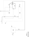
- FIG. 2 provides a flow chart in accordance with an embodiment of the present invention.
- a hydrogen feed stream 2 is introduced into a primary refrigeration system of a precooling system and cooling the hydrogen stream to a first precooling temperature.
- the precooled hydrogen stream is then introduced to a secondary refrigeration system of the precooling system and cooling the precooled hydrogen stream to a second temperature.
- the cooled hydrogen stream 22 is then liquefied in the liquefaction system to produce liquid hydrogen 32.
- oxygen is typically compressed by pumping liquid oxygen (LOX) and vaporizing it at high pressure in a main heat exchanger by heat exchange with another condensing stream (typically air).
- the condensing stream may either be at a higher pressure than the oxygen (for example using an additional BAC (booster air compressor)), or lower pressure than the oxygen (for example without a BAC using higher pressure from the MAC, a.k.a. GOK - See, e.g., U.S. Pat. 5,329,776 ].
- a significant advantage of this "GOK" cycle is the ability to produce pressurized gaseous oxygen with a single air compressor (without the BAC). With this process, the pressure from the MAC must be sufficient to meet the cold end refrigeration requirements to vaporize the oxygen. However, it also yields excessive refrigeration at the mid and warm ends, which are often valorized by either a) producing LOX, LIN and/or LAR (i.e., fatal liquid) or b) adding a cold booster, which adds heat to the process. See, e.g., U.S. Pat. 5,475,980 .
- incremental LIN can be available at very low cost relative to other operations such as the precooling portion of a hydrogen liquefier.
- the specific power of incremental LIN is only 0.3kW/Nm3 from the ASU but 0.6kW/Nm3 in the HLU.
- Hydrogen liquefaction processes require refrigeration over a very wide temperature range (300K to 20K). It is common to have separate dedicated refrigeration systems for the warm end (300K to 80K) and the cold end (80K to 20K) since the specific refrigeration demands and cost vary significantly with temperature. Regarding the warm temperature range (300K to 80K): existing technology uses a) closed loop N2 cycle, b) vaporization of LIN from an ASU, or c) mixed hydrocarbon refrigerant.
- Mixed hydrocarbon refrigerant can be the most thermodynamically efficient; however, it can also be the most expensive and is limited to process cooling to 95K to 100K before freezing hydrocarbon components and/or multi liquid phase problems. Therefore, an additional refrigeration load must be added to cover the range between 80K and 100K. This range is often compensated by additional load on the very cold refrigeration system (i.e. H 2 or He) but at a prohibitive cost. Therefore, it is desirable to have another means for this range of refrigeration.
- LIN can provide efficient refrigeration in the temperature range somewhat above 80K, it is not thermodynamically efficient for LIN to provide this complete temperature range up to 300K. As a result, this is typically limited to small liquefiers due to the extremely large quantities of LIN required making this unfeasible for large liquefiers.
- the N 2 refrigeration cycle involves compression of N 2 , partial cooling and expansion in dual turbine boosters.
- a portion of the high pressure N 2 is further cooled and expanded to 1.2 to 2 bara with a JT valve forming LIN, which is then vaporized providing refrigeration to the cooling streams at ⁇ 80K.
- this LIN vaporization pressure it is desirable for this LIN vaporization pressure to be as low as possible (e.g., 1.2 bar(a)) to provide the coldest temperature level, which is typically limited by pressure drop to rewarm and feed a low-pressure flash gas compressor.
- the ASU can use a single MAC scheme in accordance with the GOK ASU process as described above.
- This provides high-pressure oxygen (e.g., 30-40 bar(a)) to the HGU and liquid nitrogen (LIN) in a flow range of 15-50% of oxygen separation to the HLU, more preferably 25-40%.
- LAR can also optionally be produced.
- At least a portion of the LIN provides refrigeration to supplement the primary precooling refrigeration of the HLU.
- the primary precooling refrigeration may include a nitrogen turbo expander cycle, mixed hydrocarbon refrigerant cycle, ammonia cycle or similar.
- the LIN sent to the HLU is used for refrigeration purposes only, and therefore, high purity nitrogen is not required.
- purities of ⁇ 1% O2 as limited by margin to lower explosive limit of H 2 is sufficient.
- the quantity of GOX from the ASU to the HGU can be proportional to the quantity of H 2 produced and liquefied.
- the quantity of LIN to be vaporized in the HLU can be a function of the quantity of H 2 to be liquefied as well as the range of temperatures to which it is to provide cooling in the HLU.
- This temperature range in the HLU is from points 1 and 2 where Point 1 is the vaporization temperature of LIN at the lowest feasible pressure (dP of main exchanger only since it can be vented rather than feed an LP compressor).
- Point 2 the minimum temperature of the primary precooling refrigeration system.
- point 2 is the discharge temperature of the cold turbine.
- point 2 is the minimum temperature of the HC mixed refrigerant.
- the quantity of LIN to be vaporized can increase as the temperature difference between points 1 and 2 increases. If the discharge pressure of the cold N 2 turboexpander (also referred to as a turbo booster) increases, then its temperature must also increase to prevent liquid formation at the turbine outlet resulting in additional LIN flow to be vaporized.
- the discharge pressure of the cold N 2 turboexpander also referred to as a turbo booster
- LIN in the flow range of 15 to 50% of O 2 separation, more preferably 25% to 40% of O 2 separation to the HGU provides an optimum to de-couple the vaporized LIN from the N 2 refrigeration cycle, increasing the pressure of the turbine discharge, thus improving the process.
- the mass quantity of HPGOX needed in the HGU is approximately 3.3x the mass of H 2 produced from the HGU and to be liquefied n the HLU.
- the GOK-type ASU typically with single high pressure MAC
- This ASU scheme is well suited for producing LIN in the range of about 25% to 40% of the O 2 separation mass flow.
- the temperature difference (between cold end of primary refrigerant and vaporizing LIN second refrigerant) is meaningful because it directly determines the quantity of secondary refrigerant LIN needed.
- FIG. 2 provides a schematic process view of an embodiment of the present invention in which an HLU 10 is integrated with both an HGU 40 and an ASU 50.
- an air feed 4 is introduced into ASU 50 in order to produce liquid nitrogen 52 and gaseous oxygen 54.
- Gaseous oxygen 54 is then introduced into HGU 40, which can be an SMR, ATR, POX or the like, wherein a feed stream (not shown) is used along with gaseous oxygen 54 to produce high-pressure hydrogen 2.
- HLU 10 preferably comprises a precooling system 20, a liquefying system 30, a primary refrigeration system 70, a secondary refrigeration system (62,64), and a thermal insulator such as a cold-box (not shown), which provides thermal insulation for certain equipment within HLU 10 that will be exposed to temperatures below freezing.
- Precooling system 20 and liquefying system 30 preferably include heat exchangers configured to operate at cryogenic temperatures and exchange heat between two or more stream via indirect heat exchange. The types of heat exchangers used in certain embodiments can be chosen appropriately by one of ordinary skill in the art.
- High-pressure hydrogen 2 is then introduced to HLU 10, wherein it is first cooled in precooling section 20 to a temperature of about 80K to form cooled hydrogen stream 22.
- This stream 22 is then sent to liquefying system 30 under conditions effective for liquefying the cooled hydrogen stream 22 to produce liquid hydrogen 32, which is withdrawn as a product stream.
- Refrigeration for this level of cooling can be provided by a closed hydrogen (or helium) refrigeration cycle with multiple turbines and a hydrogen (or helium) recycle compressor.
- This hydrogen (or helium) compression is very difficult and expensive because of the low molecular weight (MW) or more specifically because these molecules are so small.
- Refrigeration needed to provide the cooling to produce cooled hydrogen stream 22 is provided by primary refrigeration system 70 and secondary refrigeration system 62/64.
- primary refrigeration system is a closed loop nitrogen refrigeration cycle comprising a recycle compressor 75, and first and second turbo boosters 85, 95. As the boosters of the turbo boosters are powered by turbines, the only power used in this refrigeration cycle is from the recycle compressor 75.
- secondary refrigeration system comprises vaporizing LIN 52 received from ASU 50.
- LIN 52 is introduced to gas/liquid separator 60 wherein the liquid nitrogen 62 is withdrawn from a bottom portion of gas/liquid separator 60 and warmed in precooling section 20, wherein it is then withdrawn and sent back to gas/liquid separator 60.
- Gaseous nitrogen 64 is withdrawn from a top portion of gas/liquid separator 60 before being sent to precooling section 20 for warming therein. Gaseous nitrogen is withdrawn from the warm end of the precooling section 20 and either captured for further use or vented to the atmosphere.
- FIG. 3 provides a detailed view of an embodiment using a GOK-type ASU in accordance with an embodiment of the present invention, in which the ASU also includes a turbo booster 170, 180.
- first air stream 102 is compressed in first MAC 110 to form compressed stream 112, before being fed to front-end purification unit (FEP) 130 to remove components that might freeze at cryogenic temperatures (e.g., water and carbon dioxide).
- FEP front-end purification unit
- the MAC preferably pressurizes stream 112 to an appropriate pressure level as is known by those of ordinary skill in the art, such that first portion 134 can be appropriately separated in the distillation column system 150.
- purified air stream 132 is split into a first portion 134 and a second portion 136.
- First portion 134 is kept at substantially the same pressure as the discharge of the MAC (minus pressure losses inherent in piping and equipment) and then introduced into a warm end of the main heat exchanger 140. After cooling in main heat exchanger 140, cooled first stream 142 is then introduced into distillation column system 150 for separation therein.
- Second portion 136 is further compressed in warm booster 170 to form boosted stream 172.
- the embodiment shown preferably includes cooler 171 in order to remove heat of compression from boosted stream 172 prior to introduction to main heat exchanger 140.
- warm booster 170 is coupled to turbine 180; thereby forming what is commonly referred to as a turbo-booster, which allows for the spinning of the turbine 180 to power the warm booster 170.
- Boosted stream 172 can then be sent to main heat exchanger 140 for cooling, wherein first portion 174 is withdrawn at an intermediate location and then expanded in turbine 180 to form expanded air 182, which is then introduced to distillation column system 150 for separation therein. Second portion 144 is fully cooled in heat exchanger 140 and then expanded across a Joule-Thompson valve 145 to produce additional refrigeration for the system before being introduced to the distillation column system for separation therein.
- distillation column system 150 is configured to provide a waste nitrogen stream 151, a medium pressure nitrogen stream 153, a low-pressure nitrogen stream 155 and a high-pressure gaseous oxygen stream 54.
- liquid oxygen 152 is withdrawn from the sump of the lower-pressure column (not shown) and pressurized in pump 200 before being heated in main heat exchanger 140 to form high-pressure gaseous oxygen stream 54.
- Liquid nitrogen product 52 can also be withdrawn from the distillation column system.
- Embodiments of the current invention provide improved means of operation, particularly with respect to operation of turbines.
- turndown is limited because turbine outlet pressure is fixed and equal to LIN vapor pressure.
- Turndown of the refrigeration loop can only be with flow and is limited by the machines to ⁇ 70%-80% of design (for example approach to compressor surge,..).
- the primary refrigerant e.g., N 2 expansion or mixed refrigerant
- the secondary refrigerant LIN vaporization
- the pressures throughout the primary refrigerant loop may be significantly reduced such that pressure ratios across all machines can be maintained approximately constant and operating near their best efficiency points. In certain embodiments, this yields efficient turndown to approximately ⁇ 30% of design.
- turndown is meant to include an operating case with reduced LH 2 production flowrates.
- precooling refrigeration system and cold end refrigeration system would also both need the ability to reduce refrigeration correspondingly.
- the methods known heretofore do not have much capability beyond operating at about 70-80% of design, whereas embodiments of the present invention have the capability to operate at less than 30% of design. This provides a distinct advantage in cases where demand lowers for whatever reason.
- the distillation column system 150 can be any column system that is configured to separate air into at least a nitrogen-enriched stream and an oxygen-enriched stream. This can include a single nitrogen column or a double column having a higher and lower pressure column, as is known in the art. In another embodiment, the distillation column system can also include other columns such as argon, xenon, and krypton columns. As all of these columns and systems are well known in the art, Applicant is not including detailed figures pertaining to their exact setup, as they are not necessary for an understanding of the inventive aspect of the present invention.
- a high pressure feed air compressor can include an air compressor with an output pressure of at least 15 bar(a). Additionally, as used herein, the term "about” can include natural variations that occur and include a generally accepted error range. In certain embodiments, about can include +/- 5% of a particular value.
- the present invention may suitably comprise, consist or consist essentially of the elements disclosed and may be practiced in the absence of an element not disclosed. Furthermore, if there is language referring to order, such as first and second, it should be understood in an exemplary sense and not in a limiting sense. For example, it can be recognized by those skilled in the art that certain steps can be combined into a single step or reversed in order.
- Providing in a claim is defined to mean furnishing, supplying, making available, or preparing something. The step may be performed by any actor in the absence of express language in the claim to the contrary a range is expressed, it is to be understood that another embodiment is from the one.
- Optional or optionally means that the subsequently described event or circumstances may or may not occur.
- the description includes instances where the event or circumstance occurs and instances where it does not occur.
- Ranges may be expressed herein as from about one particular value, and/or to about another particular value. When such particular value and/or to the other particular value, along with all combinations within said range.
Landscapes
- Engineering & Computer Science (AREA)
- Physics & Mathematics (AREA)
- Mechanical Engineering (AREA)
- Thermal Sciences (AREA)
- General Engineering & Computer Science (AREA)
- Health & Medical Sciences (AREA)
- Emergency Medicine (AREA)
- Separation By Low-Temperature Treatments (AREA)
Applications Claiming Priority (5)
| Application Number | Priority Date | Filing Date | Title |
|---|---|---|---|
| US202163295509P | 2021-12-30 | 2021-12-30 | |
| US17/896,967 US20230213273A1 (en) | 2021-12-30 | 2022-08-26 | Integrated industrial unit |
| US17/896,953 US20230213272A1 (en) | 2021-12-30 | 2022-08-26 | Process for precooling hydrogen for liquefaction with supplement liquid nitrogen |
| EP22854255.1A EP4457478B1 (fr) | 2021-12-30 | 2022-12-20 | Procédé de pré-refroidissement d'hydrogène pour liquéfaction avec supplément d'azote liquide |
| PCT/US2022/053549 WO2023129434A2 (fr) | 2021-12-30 | 2022-12-20 | Procédé de pré-refroidissement d'hydrogène pour liquéfaction avec supplément d'azote liquide |
Related Parent Applications (2)
| Application Number | Title | Priority Date | Filing Date |
|---|---|---|---|
| EP22854255.1A Division EP4457478B1 (fr) | 2021-12-30 | 2022-12-20 | Procédé de pré-refroidissement d'hydrogène pour liquéfaction avec supplément d'azote liquide |
| EP22854255.1A Division-Into EP4457478B1 (fr) | 2021-12-30 | 2022-12-20 | Procédé de pré-refroidissement d'hydrogène pour liquéfaction avec supplément d'azote liquide |
Publications (3)
| Publication Number | Publication Date |
|---|---|
| EP4495521A2 true EP4495521A2 (fr) | 2025-01-22 |
| EP4495521A3 EP4495521A3 (fr) | 2025-04-23 |
| EP4495521B1 EP4495521B1 (fr) | 2026-04-08 |
Family
ID=85172371
Family Applications (3)
| Application Number | Title | Priority Date | Filing Date |
|---|---|---|---|
| EP24210931.2A Pending EP4495522A3 (fr) | 2021-12-30 | 2022-12-20 | Procédé de prérefroidissement d'hydrogène pour liquéfaction avec de l'azote liquide de complément |
| EP24210930.4A Active EP4495521B1 (fr) | 2021-12-30 | 2022-12-20 | Procédé de prérefroidissement d'hydrogène pour liquéfaction avec de l'azote liquide de complément |
| EP22854255.1A Active EP4457478B1 (fr) | 2021-12-30 | 2022-12-20 | Procédé de pré-refroidissement d'hydrogène pour liquéfaction avec supplément d'azote liquide |
Family Applications Before (1)
| Application Number | Title | Priority Date | Filing Date |
|---|---|---|---|
| EP24210931.2A Pending EP4495522A3 (fr) | 2021-12-30 | 2022-12-20 | Procédé de prérefroidissement d'hydrogène pour liquéfaction avec de l'azote liquide de complément |
Family Applications After (1)
| Application Number | Title | Priority Date | Filing Date |
|---|---|---|---|
| EP22854255.1A Active EP4457478B1 (fr) | 2021-12-30 | 2022-12-20 | Procédé de pré-refroidissement d'hydrogène pour liquéfaction avec supplément d'azote liquide |
Country Status (4)
| Country | Link |
|---|---|
| EP (3) | EP4495522A3 (fr) |
| KR (1) | KR20240132040A (fr) |
| AU (1) | AU2022429663B2 (fr) |
| WO (1) | WO2023129434A2 (fr) |
Families Citing this family (1)
| Publication number | Priority date | Publication date | Assignee | Title |
|---|---|---|---|---|
| EP4617596A1 (fr) * | 2024-03-12 | 2025-09-17 | L'air Liquide, Societe Anonyme Pour L'etude Et L'exploitation Des Procedes Georges Claude | Procédé de production d'hydrogène liquéfié |
Citations (5)
| Publication number | Priority date | Publication date | Assignee | Title |
|---|---|---|---|---|
| US2983585A (en) | 1957-12-11 | 1961-05-09 | British Oxygen Co Ltd | Preparation of liquid hydrogen |
| US3347055A (en) | 1965-03-26 | 1967-10-17 | Air Reduction | Method for recuperating refrigeration |
| US5329776A (en) | 1991-03-11 | 1994-07-19 | L'air Liquide, Societe Anonyme Pour L'etude Et L'exploitation Des Procedes Georges Claude | Process and apparatus for the production of gaseous oxygen under pressure |
| US5475980A (en) | 1993-12-30 | 1995-12-19 | L'air Liquide, Societe Anonyme Pour L'etude L'exploitation Des Procedes Georges Claude | Process and installation for production of high pressure gaseous fluid |
| JP2002243360A (ja) | 2001-02-19 | 2002-08-28 | Air Liquide Japan Ltd | 液体水素の製造方法および液体水素の製造設備 |
Family Cites Families (2)
| Publication number | Priority date | Publication date | Assignee | Title |
|---|---|---|---|---|
| US10634425B2 (en) * | 2016-08-05 | 2020-04-28 | L'air Liquide, Societe Anonyme Pour L'etude Et L'exploitation Des Procedes Georges Claude | Integration of industrial gas site with liquid hydrogen production |
| AU2021261350B2 (en) * | 2020-04-22 | 2024-05-02 | L'air Liquide, Societe Anonyme Pour L'etude Et L'exploitation Des Procedes Georges Claude | Nitrogen process for production of ammonia and liquid hydrogen |
-
2022
- 2022-12-20 EP EP24210931.2A patent/EP4495522A3/fr active Pending
- 2022-12-20 KR KR1020247025387A patent/KR20240132040A/ko active Pending
- 2022-12-20 WO PCT/US2022/053549 patent/WO2023129434A2/fr not_active Ceased
- 2022-12-20 EP EP24210930.4A patent/EP4495521B1/fr active Active
- 2022-12-20 AU AU2022429663A patent/AU2022429663B2/en active Active
- 2022-12-20 EP EP22854255.1A patent/EP4457478B1/fr active Active
Patent Citations (5)
| Publication number | Priority date | Publication date | Assignee | Title |
|---|---|---|---|---|
| US2983585A (en) | 1957-12-11 | 1961-05-09 | British Oxygen Co Ltd | Preparation of liquid hydrogen |
| US3347055A (en) | 1965-03-26 | 1967-10-17 | Air Reduction | Method for recuperating refrigeration |
| US5329776A (en) | 1991-03-11 | 1994-07-19 | L'air Liquide, Societe Anonyme Pour L'etude Et L'exploitation Des Procedes Georges Claude | Process and apparatus for the production of gaseous oxygen under pressure |
| US5475980A (en) | 1993-12-30 | 1995-12-19 | L'air Liquide, Societe Anonyme Pour L'etude L'exploitation Des Procedes Georges Claude | Process and installation for production of high pressure gaseous fluid |
| JP2002243360A (ja) | 2001-02-19 | 2002-08-28 | Air Liquide Japan Ltd | 液体水素の製造方法および液体水素の製造設備 |
Non-Patent Citations (1)
| Title |
|---|
| QUACK: "Adv. Cryog. Eng., Proc. CEC", vol. 613, 2001, AIP, article "Conceptual Design of a High Efficiency Large Capacity Hydrogen Liquefier", pages: 255 - 263 |
Also Published As
| Publication number | Publication date |
|---|---|
| WO2023129434A3 (fr) | 2023-08-10 |
| EP4495522A2 (fr) | 2025-01-22 |
| EP4495521A3 (fr) | 2025-04-23 |
| EP4457478B1 (fr) | 2026-02-25 |
| AU2022429663A1 (en) | 2024-08-15 |
| EP4495521B1 (fr) | 2026-04-08 |
| AU2022429663B2 (en) | 2026-01-08 |
| EP4495522A3 (fr) | 2025-04-30 |
| EP4457478A2 (fr) | 2024-11-06 |
| KR20240132040A (ko) | 2024-09-02 |
| WO2023129434A2 (fr) | 2023-07-06 |
Similar Documents
| Publication | Publication Date | Title |
|---|---|---|
| AU2021416497B2 (en) | Methods and systems for hydrogen liquefaction | |
| AU2010283530B2 (en) | Refrigerant composition control | |
| US5141543A (en) | Use of liquefied natural gas (LNG) coupled with a cold expander to produce liquid nitrogen | |
| US7143606B2 (en) | Combined air separation natural gas liquefaction plant | |
| US20130118204A1 (en) | Integrated liquid storage | |
| AU2017305523A1 (en) | Integration of industrial gas site with liquid hydrogen production | |
| US12181215B2 (en) | Hydrogen liquefier | |
| KR102488158B1 (ko) | 질소 제거에 의한 lng 생산 | |
| EP4457478B1 (fr) | Procédé de pré-refroidissement d'hydrogène pour liquéfaction avec supplément d'azote liquide | |
| US10612842B2 (en) | LNG integration with cryogenic unit | |
| US20230213273A1 (en) | Integrated industrial unit | |
| US20250198695A1 (en) | Method for liquefying a methane-rich feed gas, and corresponding facility | |
| Wanner et al. | Concept and operation of a 4.4 ton/d liquid hydrogen facility | |
| AU2024227743A1 (en) | Installation and method for producing liquefied hydrogen |
Legal Events
| Date | Code | Title | Description |
|---|---|---|---|
| PUAI | Public reference made under article 153(3) epc to a published international application that has entered the european phase |
Free format text: ORIGINAL CODE: 0009012 |
|
| STAA | Information on the status of an ep patent application or granted ep patent |
Free format text: STATUS: THE APPLICATION HAS BEEN PUBLISHED |
|
| AC | Divisional application: reference to earlier application |
Ref document number: 4457478 Country of ref document: EP Kind code of ref document: P |
|
| AK | Designated contracting states |
Kind code of ref document: A2 Designated state(s): AL AT BE BG CH CY CZ DE DK EE ES FI FR GB GR HR HU IE IS IT LI LT LU LV MC ME MK MT NL NO PL PT RO RS SE SI SK SM TR |
|
| XX | Miscellaneous (additional remarks) |
Free format text: MISSING OR CORRECT PARTS INCLUDED UNDER RULE 56(3) OR RULE 56A(4) EPC |
|
| PUAL | Search report despatched |
Free format text: ORIGINAL CODE: 0009013 |
|
| AK | Designated contracting states |
Kind code of ref document: A3 Designated state(s): AL AT BE BG CH CY CZ DE DK EE ES FI FR GB GR HR HU IE IS IT LI LT LU LV MC ME MK MT NL NO PL PT RO RS SE SI SK SM TR Free format text: MISSING OR CORRECT PARTS INCLUDED UNDER RULE 56(3) OR RULE 56A(4) EPC |
|
| RIC1 | Information provided on ipc code assigned before grant |
Ipc: F25J 1/00 20060101AFI20250319BHEP |
|
| STAA | Information on the status of an ep patent application or granted ep patent |
Free format text: STATUS: REQUEST FOR EXAMINATION WAS MADE |
|
| 17P | Request for examination filed |
Effective date: 20251023 |
|
| GRAP | Despatch of communication of intention to grant a patent |
Free format text: ORIGINAL CODE: EPIDOSNIGR1 |
|
| RIN1 | Information on inventor provided before grant (corrected) |
Inventor name: TURNEY, MIKE Inventor name: GUILLARD, ALAIN Inventor name: CHAN, BOBBY MON-FLAN |
|
| STAA | Information on the status of an ep patent application or granted ep patent |
Free format text: STATUS: GRANT OF PATENT IS INTENDED |
|
| GRAS | Grant fee paid |
Free format text: ORIGINAL CODE: EPIDOSNIGR3 |
|
| GRAA | (expected) grant |
Free format text: ORIGINAL CODE: 0009210 |
|
| STAA | Information on the status of an ep patent application or granted ep patent |
Free format text: STATUS: THE PATENT HAS BEEN GRANTED |
|
| INTG | Intention to grant announced |
Effective date: 20260225 |
|
| AC | Divisional application: reference to earlier application |
Ref document number: 4457478 Country of ref document: EP Kind code of ref document: P |
|
| AK | Designated contracting states |
Kind code of ref document: B1 Designated state(s): AL AT BE BG CH CY CZ DE DK EE ES FI FR GB GR HR HU IE IS IT LI LT LU LV MC ME MK MT NL NO PL PT RO RS SE SI SK SM TR |
|
| REG | Reference to a national code |
Ref country code: CH Ref legal event code: F10 Free format text: ST27 STATUS EVENT CODE: U-0-0-F10-F00 (AS PROVIDED BY THE NATIONAL OFFICE) Effective date: 20260408 Ref country code: GB Ref legal event code: FG4D |
|
| XX | Miscellaneous (additional remarks) |
Free format text: MISSING OR CORRECT PARTS INCLUDED UNDER RULE 56(3) OR RULE 56A(4) EPC |