EP4495543A1 - Schlammdickenmessverfahren und schlammdickenmessvorrichtung - Google Patents
Schlammdickenmessverfahren und schlammdickenmessvorrichtung Download PDFInfo
- Publication number
- EP4495543A1 EP4495543A1 EP22896824.4A EP22896824A EP4495543A1 EP 4495543 A1 EP4495543 A1 EP 4495543A1 EP 22896824 A EP22896824 A EP 22896824A EP 4495543 A1 EP4495543 A1 EP 4495543A1
- Authority
- EP
- European Patent Office
- Prior art keywords
- sludge
- depth
- receiver
- transmitter
- waves
- Prior art date
- Legal status (The legal status is an assumption and is not a legal conclusion. Google has not performed a legal analysis and makes no representation as to the accuracy of the status listed.)
- Pending
Links
Images
Classifications
-
- G—PHYSICS
- G01—MEASURING; TESTING
- G01C—MEASURING DISTANCES, LEVELS OR BEARINGS; SURVEYING; NAVIGATION; GYROSCOPIC INSTRUMENTS; PHOTOGRAMMETRY OR VIDEOGRAMMETRY
- G01C13/00—Surveying specially adapted to open water, e.g. sea, lake, river or canal
- G01C13/008—Surveying specially adapted to open water, e.g. sea, lake, river or canal measuring depth of open water
-
- G—PHYSICS
- G01—MEASURING; TESTING
- G01B—MEASURING LENGTH, THICKNESS OR SIMILAR LINEAR DIMENSIONS; MEASURING ANGLES; MEASURING AREAS; MEASURING IRREGULARITIES OF SURFACES OR CONTOURS
- G01B17/00—Measuring arrangements characterised by the use of infrasonic, sonic or ultrasonic vibrations
- G01B17/02—Measuring arrangements characterised by the use of infrasonic, sonic or ultrasonic vibrations for measuring thickness
-
- G—PHYSICS
- G01—MEASURING; TESTING
- G01F—MEASURING VOLUME, VOLUME FLOW, MASS FLOW OR LIQUID LEVEL; METERING BY VOLUME
- G01F23/00—Indicating or measuring liquid level or level of fluent solid material, e.g. indicating in terms of volume or indicating by means of an alarm
- G01F23/22—Indicating or measuring liquid level or level of fluent solid material, e.g. indicating in terms of volume or indicating by means of an alarm by measuring physical variables, other than linear dimensions, pressure or weight, dependent on the level to be measured, e.g. by difference of heat transfer of steam or water
- G01F23/28—Indicating or measuring liquid level or level of fluent solid material, e.g. indicating in terms of volume or indicating by means of an alarm by measuring physical variables, other than linear dimensions, pressure or weight, dependent on the level to be measured, e.g. by difference of heat transfer of steam or water by measuring the variations of parameters of electromagnetic or acoustic waves applied directly to the liquid or fluent solid material
- G01F23/296—Acoustic waves
- G01F23/2962—Measuring transit time of reflected waves
-
- G—PHYSICS
- G01—MEASURING; TESTING
- G01S—RADIO DIRECTION-FINDING; RADIO NAVIGATION; DETERMINING DISTANCE OR VELOCITY BY USE OF RADIO WAVES; LOCATING OR PRESENCE-DETECTING BY USE OF THE REFLECTION OR RERADIATION OF RADIO WAVES; ANALOGOUS ARRANGEMENTS USING OTHER WAVES
- G01S15/00—Systems using the reflection or reradiation of acoustic waves, e.g. sonar systems
- G01S15/88—Sonar systems specially adapted for specific applications
-
- G—PHYSICS
- G01—MEASURING; TESTING
- G01S—RADIO DIRECTION-FINDING; RADIO NAVIGATION; DETERMINING DISTANCE OR VELOCITY BY USE OF RADIO WAVES; LOCATING OR PRESENCE-DETECTING BY USE OF THE REFLECTION OR RERADIATION OF RADIO WAVES; ANALOGOUS ARRANGEMENTS USING OTHER WAVES
- G01S7/00—Details of systems according to groups G01S13/00, G01S15/00, G01S17/00
- G01S7/52—Details of systems according to groups G01S13/00, G01S15/00, G01S17/00 of systems according to group G01S15/00
- G01S7/56—Display arrangements
- G01S7/62—Cathode-ray tube displays
- G01S7/6218—Cathode-ray tube displays providing two-dimensional coordinated display of distance and direction
-
- G—PHYSICS
- G01—MEASURING; TESTING
- G01S—RADIO DIRECTION-FINDING; RADIO NAVIGATION; DETERMINING DISTANCE OR VELOCITY BY USE OF RADIO WAVES; LOCATING OR PRESENCE-DETECTING BY USE OF THE REFLECTION OR RERADIATION OF RADIO WAVES; ANALOGOUS ARRANGEMENTS USING OTHER WAVES
- G01S7/00—Details of systems according to groups G01S13/00, G01S15/00, G01S17/00
- G01S7/52—Details of systems according to groups G01S13/00, G01S15/00, G01S17/00 of systems according to group G01S15/00
- G01S7/56—Display arrangements
- G01S7/62—Cathode-ray tube displays
- G01S7/6272—Cathode-ray tube displays producing cursor lines and indicia by electronic means
Definitions
- the present invention relates to a sludge thickness measuring method and a sludge thickness measuring device for rivers and the like.
- the present invention relates to a sludge thickness measuring method and a sludge thickness measuring device for causing one ultrasonic transmitter/receiver to transmit and receive ultrasonic waves to measure a surface depth and a bottom depth of a sludge layer.
- the present invention relates to a sludge thickness measuring device comprising a small-scale crewless catamaran unnecessary to be boarded by a crew and capable of acquiring sludge layer information comprising the surface depth and the bottom depth of the sludge layer together with accurate latitude and longitude information.
- the bottom sediment sludge layer (hereinafter referred to as the sludge layer) containing pollutants piles up over the sand layer or base rock layer, which forms the bottom of rivers, dam lakes, lakes, reservoirs, canals, or ports (hereinafter referred to as rivers and the like).
- the sludge layer With the sludge layer being piled up, not only the habitat environment of fish and shellfish deteriorates, but also deterioration in the water quality or a bad smell is caused in canals; deterioration in the water quality of discharged water is caused in dam lakes; the accumulation inhibits port functions such as the ship sailing in ports; holding necessary agricultural water becomes difficult in reservoirs; or flood control functions cannot be maintained.
- the accumulated sludge layer does not naturally disappear and can be removed only by dredging.
- dredging In order to maintain the water quality of rivers and the like in good condition, dredging must be done efficiently, and the sludge layer thickness must be measured periodically beforehand. Conventionally, the layer thickness of the accumulated layer in the rivers and the like was measured by crew members boarding the inspection ship pushing a rod body into the bottom.
- Patent Document 1 a technology of sludge layer survey apparatus is disclosed, in which the sludge layer thickness is measured by transmitting high-band ultrasonic waves of 100kHz and 90kHz simultaneously from two ultrasonic transmitters/receivers. It is said that the interaction of the two ultrasonic waves generates inside water low-band ultrasonic of 10kHz, "the difference component" of the ultrasonic waves, which makes it possible to generate the ultrasonic signal with sharp directivity, to make the size of the ultrasonic transmitter smaller, and to eliminate deviation of transmitting point as well.
- the wide-band ultrasonic waves of "the sum component” reflect at the surface depth of the sludge layer for measuring the depth from the water surface to the sludge layer surface, and the 10kHz low-band ultrasonic waves of "the difference component” pass through the sludge layer and reflect at the bottom depth, whereby the thickness of the sludge layer (hereinafter referred to as sludge thickness)can be measured.
- sludge thickness the thickness of the sludge layer
- Patent Document 2 high-band ultrasonic waves and different band ultrasonic waves different from the said ultrasonic waves by the frequency ⁇ are simultaneously transmitted from one ultrasonic transmitter/receiver, and the reflected waves with two bands caused by the high-band ultrasonic waves and the low-band ultrasonic waves generated by the interaction of the two ultrasonic waves are received by the one ultrasonic transmitter/receiver, and the thickness of the sludge layer is measured by separating and amplifying them.
- an ultrasonic transmitter/receiver to generate only low-band ultrasonic waves became unnecessary, there was a problem that time errors occurred in the propagation timing of the ultrasonic signals.
- Patent Document 3 A technology to equip a delay circuit to eliminate the time errors in the propagation timing is disclosed in Patent Document 3.
- the rigid body in order to measure the time to be delayed by the delay circuit, the rigid body should be placed in the water beforehand, and the signals of high-band ultrasonic waves and low-band ultrasonic waves reflected on the rigid body need to be measured beforehand, which caused the problem that labor and time are necessary.
- Patent Document 4 a technology of measurement system is disclosed, which identifies the location of a survey ship by a ground base station and a GPS (Global Positioning System) positioning device on board the survey ship, and measures the water depth by transmitting 200kHz ultrasonic waves from the ultrasonic transmitter/receiver and stores the location information, the depth information, and the time information as one unit in the storage device.
- GPS Global Positioning System
- the technology in the case of measuring the bottom sediment quality of the lake bottom together, it is said to be appropriate to transmit ultrasonic waves of 2kHz to 12kHz from the measurement device for the bottom sediment quality different from the ultrasonic transmitter/receiver.
- the ground base station is inevitable in addition to the survey ship to correct the errors of location information of the GPS positioning device on board the survey ship, which makes the measurement system large-scale.
- the ultrasonic waves having different wavelengths respectively need to be transmitted from the two devices producing ultrasonic waves, causing a problem that the system became complicated.
- the inventor of the present invention takes it as a problem to provide a sludge thickness measuring method and a sludge thickness measuring device, which can measure the depth of the surface and bottom of a sludge layer by causing the single ultrasonic transmitter/receiver to transmit and receive ultrasonic waves.
- the first invention of the present invention among sludge thickness measuring methods to measure the sludge thickness by causing the transmitter/receiver provided on the water surface to transmit and receive ultrasonic waves is characterized as follows: as for the transmitter/receiver, the distance from the outer edge of the irradiation radius at the presumed surface depth of the sludge layer to the transmitter/receiver is shorter than the distance from the irradiation center at the presumed bottom depth of the sludge layer to the transmitter/receiver, and also, a single transmitter/receiver which transmits and receives ultrasonic waves with a single frequency that reflect not only on the surface of the sludge layer but also on the bottom surface of the sludge layer is selected; the said single transmitter/receiver transmits and receives ultrasonic waves of the said frequency; the phenomenon is confirmed by receiving ultrasonic waves transmitted from the said single transmitter/receiver by the said single transmitter/receiver that while the intensity of the surface reflected waves received
- the water depth to the water bottom i.e., the surface depth of the sludge layer
- the approximate ratio of the sludge thickness to the surface depth is presumed to be such as 10 % or 100 %.
- the transmitter/receiver may be selected as having an irradiation angle in which the distance from the outer edge of the irradiation radius of the ultrasonic waves on the surface depth to the transmitter/receiver is shorter than the distance from the irradiation center of the ultrasonic waves on the bottom depth of the sludge layer to the transmitter/receiver.
- the inventor of the present invention tried measuring the water bottom using two kinds of ultrasonic transmitters/receivers with frequencies of 28 kHz and 50 kHz. While with the transmitter/receiver with 50 kHz frequency, the reflected waves from the sludge layer surface and the reflected waves from the bottom surface were difficult to distinguish, with the ultrasonic transmitter/receiver with 28 kHz frequency, the surface reflected waves from the surface and the bottom surface reflected waves from the bottom surface were distinguished, which led to the present invention.
- the reflected waves are accumulated from the arrival of the surface reflected waves from the center of the irradiation range on the sludge surface until the arrival of the surface reflected waves from the outer edge of the irradiation range, thus the measured intensity of reflected waves gradually increase.
- the intensity of the bottom surface reflected waves from the sludge bottom surface is similar too.
- the distance from the bottom surface of the sludge layer is larger than the distance from the outer edge of the irradiation radius on the surface depth of the sludge layer to the transmitter/receiver, there is a time lag since the surface reflected waves reflect on the outer edge on the sludge surface until the bottom surface reflected waves from the center of the sludge bottom surface arrive.
- the phenomenon where the intensity of the surface reflected waves from the sludge surface gradually increases, and gradually decreases after passing the inflection point is measured.
- the height of the surface and the height of the bottom surface of the sludge layer are estimated.
- the sludge thickness measuring method of the first invention favorable effects in that depths of the surface and the bottom surface of the sludge layer can be estimated even by transmitting and receiving ultrasonic waves with a single frequency, and measurement of sludge thickness is possible and easy even with a single transmitter/receiver are achieved.
- the second invention of the present invention is the sludge thickness measuring method of the first invention and is further characterized as follows: comparing the first time from the transmission of the ultrasonic waves to the gradual increase starting point in the intensity of the received surface reflected waves and the second time from the gradual increase starting point in the intensity of the received surface reflected waves to the gradual increase starting point in the intensity of the reflected waves that are received secondary waves caused by re-reflection of the said surface reflected waves returned to the water surface; the said surface depth is determined based on approximation between the first time and the second time, and the estimated sludge thickness is determined to be the correct thickness of the sludge layer.
- the ultrasonic waves reflect on the sludge surface, and the ultrasonic waves that return to the water surface reflect at the location of the transmitter/receiver and go to the water bottom, becoming the secondary waves.
- the secondary waves again reflect on the sludge surface, and the gradual increase in the intensity of the secondary waves is measured by the transmitter/receiver.
- the gradual increase starting point in the secondary waves is the distance equivalent to two roundtrip distances from the ultrasonic transmission to the surface of the sludge layer; thus, the surface depth of the sludge layer is determined based on approximation between the first time and the second time, and the estimated sludge layer can be determined to be the correct sludge thickness.
- the approximation is not necessarily limited to a match due to the effect of growth, etc. in the water, and an error of 20 to 40 % is allowable.
- the surface depth of the sludge layer estimated by the first invention is endorsed, causing a favorable effect in that the sludge thickness estimated using ultrasonic waves with a single frequency can be determined to be the correct sludge thickness.
- the third invention of the present invention in sludge thickness measuring devices to measure the sludge thickness by causing a transmitter/receiver provided on the water surface to transmit and receive ultrasonic waves is characterized as follows: a sludge layer bottom confirmation means and a sludge thickness estimation means are comprised; the said transmitter/receiver is a single transmitter/receiver capable of transmitting and receiving ultrasonic waves with a single frequency; the irradiation angle of the said transmitter/receiver is set at an angle where the distance from the outer edge of the irradiation radius at the presumed surface depth of the sludge layer to the transmitter/receiver is shorter than the distance from the irradiation center at the presumed bottom depth of the sludge layer to the transmitter/receiver, and also, the frequency of the said transmitter/receiver is set in a frequency that reflects not only on the surface of the sludge layer but also on the bottom surface; the said sludge layer bottom confirmation
- the sludge thickness measuring device of the third invention is a device to conduct the sludge thickness measuring method of the first invention, and can estimate the sludge thickness with only a single transmitter/receiver, causing an advantageous effect in that the measurement of sludge thickness is easy.
- the fourth invention of the present invention is the sludge thickness measuring device of the third invention and is further characterized as follows: a surface depth determination means and a sludge thickness determination means are comprised; the said surface depth determination means can compare the first time from the transmission of the ultrasonic waves to the gradual increase starting point in the intensity of the said surface reflected waves and the second time from the gradual increase starting point in the intensity of the said surface reflected waves to the gradual increase starting point in the intensity of the secondary reflected waves of re-reflection of the said surface reflected waves returned to the water surface; and the said surface depth can be determined by approximation between the first time and the second time, and the said sludge thickness determination means can determine the estimation of the said sludge thickness to be the correct thickness of the sludge layer.
- the approximation is not necessarily limited to a match due to the effect of growth, etc., in the water, and an error up to about 20 % is allowable.
- the sludge thickness measuring device of the fourth invention is a device to conduct the sludge thickness measuring method of the second invention and has a favorable effect in that the sludge thickness estimated using a single transmitter/receiver can be determined to be the correct sludge thickness.
- the fifth invention of the present invention is the sludge thickness measuring device of the third or the fourth invention and characterized in that the frequency of the ultrasonic waves is the frequency not exceeding 50 kHz.
- the sludge bottom surface could be recognized with ultrasonic waves of 28 kHz.
- ultrasonic waves of 28 kHz or more and less than 50 kHz can be used. According to the fifth invention, there is a favorable effect in that the sludge thickness can be measured even with a frequency of 50 kHz or less.
- the sixth invention of the present invention is the sludge thickness measuring device from the third to the fifth invention and characterized in that the said frequency is a frequency of 28 kHz or less.
- the sludge bottom surface can be clearly measured, and it is preferable.
- Patent Document 1 and the like since it is known publicly that a sludge bottom surface can be measured by ultrasonic waves with less than 28 kHz, for example, ultrasonic waves from 2 kHz to 10 kHz, it is obvious that the frequency of low-band ultrasonic waves is not limited.
- the seventh invention of the present invention is characterized in that the transmitter/receiver described in the third to the sixth invention is boarded in touch with the water surface in the central location of a small-scale crewless catamaran moved by wireless control.
- the sludge thickness measuring device can easily transmit ultrasonic waves directly downward from the central portion of the small-scale crewless catamaran; the secondary waves reflect not only on the transmitter/receiver but also on the overall bottom surface of the small-scale crewless catamaran, eliminating reflections from the wavy water surface, the reflected waves of the secondary waves are clearly identified; thereby causing an effect in that the measurement of the secondary waves is easy.
- the eighth invention of the present invention in the sludge thickness measuring device of the seventh invention, is characterized as follows: the said small-scale crewless catamaran is provided with a GPS positioning device; the latitude/longitude information is measured by at least four satellites with an elevation angle of 70 degrees or more; the said latitude/longitude information, the said surface depth, the said bottom depth, and the time information at the time of measuring them are recorded together.
- the location is captured by four or more satellites located within an elevated angle of seventy degrees or more close to directly above without being shielded by the surrounding artificial objects.
- the accurate latitude/longitude information of the sludge thickness measuring device is measured without any intermission. Because the latitude/longitude information, the said surface depth, and the said bottom depth of the sludge layer are accurately measured, an effect appears that the volume of sludge to be dredged is also accurately figured out. Moreover, since the time information is also recorded together, an effect in that the water level influence caused by the high and low tide is also recorded together is obtained.
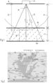
- the distance (Z) from the outer edge (R) of the irradiation radius at the presumed surface depth (X) of the sludge layer (refer to FIG. 1 ) to the transmitter/receiver is shorter than the distance from the irradiation center C at the presumed bottom depth (X+Y) of the sludge layer to the transmitter/receiver, and moreover, using the transmitter/receiver 10 which transmits the ultrasonic waves with a frequency that reflects on the surface and the bottom surface of the sludge layer, the sludge thickness was measured based on the time lag between the reception (a) (refer to FIG. 4 ) of the surface reflected waves of the sludge layer and the reception (c) of the bottom surface reflected waves.
- FIG. 1 shows an explanatory drawing of the sludge thickness measuring method.
- FIG. 2 shows an explanatory drawing of the measuring sites in the measuring experiments in Lake Hamana.
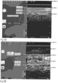
- FIG. 3(A) shows the measurement results of the sludge thickness at the first measuring site shown in FIG. 2
- FIG. 3(B) shows the measurement results of the sludge thickness at the second measuring site shown in FIG. 2 .
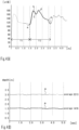
- FIG. 4 shows an explanatory drawing of the reflected waves measured at the third measuring site shown in FIG. 2 .
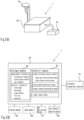
- FIG. 5(A) shows a schematic drawing of the sludge thickness measuring device 1
- FIG. 5(B) shows a block diagram of the sludge thickness measuring device 1.
- a depth from the water surface to the surface of the sludge layer (hereinafter referred to as surface depth) and a depth from the water surface to the bottom surface of the sludge layer (hereinafter referred to as bottom depth) are measured by either of the following methods: a person thrusts a measuring rod into the sludge layer and catches a response to the hand or penetrates a tip of the cone to the sludge layer and measures the resistance value in a cone-penetrating test.
- a sludge thickness As a specific example of a sludge thickness, according to the multiple cone-penetrating tests in Horikawa River in Nagoya City, Aichi Prefecture, conducted on January 12, 2009, the surface depth of about 1.5 m, the bottom depth of about 2.5 m to about 3.0 m were measured, and the measurement result of the sludge thickness was about 1 m to about 1.5 m. With these test results, the proportion of the sludge thickness to the surface depth was about 70 % to 100 %, which was supposed to be a large proportion.
- the upper layer side tends to be a soft layer, and the lower layer side tends to be a hard layer.
- a measurement by a low band ultrasonic of about 10 kHz was necessary.
- the inventor and others based on the results of the said investigation, on July 7, 2020, and July 8, the same year, tried measuring tests of the sludge layer by ultrasonic waves with 28 kHz frequency at the measuring sites in Hamana Lake ( FIG. 2 ), Shizuoka Prefecture bordering the sea. In these measuring tests, with the ultrasonic waves of 28 kHz, the surface depth and the bottom depth could be measured by a single frequency.
- the transmitter/receiver may be selected according to the previously presumed sludge thickness in response to measuring objects such as rivers, dam lakes, lakes, reservoirs, canals, or ports.
- a dam lake based on the flood control capacity designed to maintain a normal function of the flowing water, the service water capacity, and the sediment storage capacity, the sludge thickness may be presumed.
- the sludge thickness may be presumed based on the previously mentioned preliminary investigation results, etc.
- a transmitter/receiver having the predetermined irradiation angle to conform to the presumed surface depth and sludge thickness is selected.
- the irradiation angle of the ultrasonic waves is an angle at which the ultrasonic waves transmitted from the transmitter/receiver spread; the ultrasonic waves are irradiated so that the range where the irradiation angle is the outer edge is the irradiation range.
- the irradiation angle may be selected by the directivity angle displayed as an angle at which the intensity of ultrasonic waves attenuates to about 1/2 in the 1 m distance from the transmitter/receiver.
- the ultrasonic waves transmitted directly downwards from the transmitter/receiver 10 towards the sludge layer 100 go toward the center (C) of irradiation range in the shortest distance and reflect on the surface of the sludge layer (refer to solid arrow). Since as going from the center of the irradiation range toward the outer edge, the reflecting distance gradually increases, and the time at which the transmitter/receiver receives the reflected waves gradually delays; thereby, the intensity of the received reflected waves accumulates and gradually increases from the center (C) to the outer edge (R), and gradually decreases from the inflection point of the outer edge (R) (refer to a to c in FIG.
- the intensity of the bottom surface reflected waves (refer to dotted arrow) from the bottom surface of the sludge layer also gradually increases and, after passing the inflection point, gradually decreases (refer to c to e in FIG. 4 (A) ).
- a part of ultrasonic waves transmitted through the inside of the sludge layer 100 reflects on the bottom surface of the sludge layer.
- the transmitter/receiver having an irradiation angle, in which the distance (Z) from the outer edge (R) of the irradiation radius at the presumed surface depth X to the transmitter/receiver 10 is shorter than the distance (X+Y) from the irradiation center at the bottom depth of the sludge layer to the transmitter/receiver, the intensity of the reflected waves lowers by the time lag responding to the distance difference (D).
- the presumed surface depth from the water surface A is (X)
- the presumed sludge thickness is (Y)
- the distance from the outer edge (R) of the irradiation radius at the presumed surface depth (X) to the transmitter/receiver is (Z).
- ⁇ the irradiation angle
- X + Y > Z Z ⁇ cos ⁇ 2 X
- a transmitter/receiver of ultrasonic waves one having a directivity angle of a small angle of 8 degrees to 30 degrees in the case of a transmitter/receiver used mainly in the atmosphere, and one having a wide directivity angle of a wide angle of about 60 degrees in the case for wide-range fish detection inside the water are practically used.
- the directivity angle should be smaller than 96.2 degrees, and most transmitters/receivers including a transmitter/receiver for fish detection can be adopted.
- the sludge layer ratio being small like dam lakes where the ratio of sludge layer is in the range of about 5 %, there are many transmitters/receivers with a small directivity angle of less than about 35.4 degrees, and if the transmitter/receiver with a small directivity angle is selected among them, it can be practically used.
- FIG. 2 shows the schematic drawing of measuring sites from the first to the third and Lake Hamana.
- FIG. 3(A) shows the measurement data acquired on July 7 at 10:56 am at the first measuring site.
- FIG. 3(B) shows the measurement data acquired on July 7 at 12:13 pm at the second measuring site.
- FIG. 4(A) shows the measurement test results in the graph conducted on July 8, 2020, at 9:36 am.
- the sludge thickness measuring device and the GPS positioning device were on board a ship, and the acquired reflected wave information, the latitude/longitude information, and the time information were recorded together.
- the left side of the drawing shows a map of the measuring site based on the latitude/longitude information, and also, on the right side of the drawing, the drawing that represents the binarized intensity of reflected waves is shown.
- the measurement time, the tide level graph of high and low tides, and the direction are shown together on this map.
- the ultrasonic transmitter/receiver transmitted and received ultrasonic waves 125 times for 5 seconds with an interval of 0.04 seconds, and the measurements were done.
- the first measuring site was the site of Lake Hamana at 34 degrees 47.463 minutes north latitude and 137 degrees 38.557 minutes east longitude (refer to FIG. 2 and FIG. 3(A) ).
- the first measuring site was the site in the shallow part of Lake Hamana, about 350 m south-southwest from the mouth of the Miyakoda River that flows in.
- the surface depth was about 1.0 m
- the bottom depth was about 1.5 m
- the thickness of the sludge layer was about 0.5 m.
- a person thrust a measuring rod into the sludge and measured the sludge thickness, and the results were almost the same.
- the second measuring site was set at the site of 34 degrees 46.040 minutes north latitude and 137 degrees 37.709 minutes east longitude on Lake Hamana (refer to FIG. 2 and FIG. 3(B) ).
- the second measuring site was the site in the shallow part of Lake Hamana, about 100m south of the mouth of the Kurematsu River that flows in.
- the surface depth was about 1.8 m
- the bottom depth was about 3.1 m
- the thickness of the sludge layer was about 1.3 m.
- a person thrust a measuring rod into the sludge and measured the sludge thickness, and the results were almost the same.
- the third measuring site was at the site of 34 degrees 47.4626 minutes north latitude and 137 degrees 38.5555 minutes east longitude, and the location apart from the mouth of the Miyakoda River in the southwest direction from the first measuring site (refer to FIG. 2 ). Due to the influence of high and low tides, at the time of the third measurement, the measurement was done at the tide level of about 0.4 m higher than that of the first measurement experiment conducted the previous day.
- FIG. 4(A) shows the intensity of the surface reflected waves (a to c indicated by a solid line), the bottom reflected waves (c to e indicated by a dotted line), and the secondary waves (e ⁇ indicated by a one-dot chain line) in a line graph, which were measured using the transmitter/receiver with a predetermined irradiation angle and 28 kHz of frequency.
- the vertical axis indicates the intensity of the reflected waves
- the horizontal axis indicates the depth, which is the moving distance of the ultrasonic waves.
- FIG. 4(A) shows the average value of the surface depth (X: refer to FIG. 1 ) estimated from the surface reflected waves when measuring the reflected waves multiple times over 5 seconds at the same point (refer to a, in the same FIG.), and the average value of the surface depth for two round trips estimated from the secondary wave (refer to e, in the same FIG.).
- the sludge thickness can be estimated by distinguishing between the surface reflected waves and the bottom reflected waves using only a single frequency of ultrasonic waves.
- the surface depth is estimated to be about 1.5 m from the depth from the ultrasonic wave transmission to the gradually increasing starting point a of the surface reflected waves.
- the bottom depth is estimated to be about 2.0 m from the depth from the ultrasonic wave transmission to the gradual increase starting point c of the bottom reflected waves.
- the sludge thickness is estimated to be about 0.5m from this difference.
- the tide level in the measurement experiment at the third measuring site was about 0.4 m higher than the tide level in the measurement experiment at the first measuring site (refer to Fig. 2 ).
- the surface depth was about 1.1 m, and the approximate result of the surface depth of about 1.0 m at the nearby first measuring site was obtained.
- the bottom depth at the third measuring site considering the tide level was about 1.6 m, and the bottom depth at the first measuring site was about 1.5 m, also resulting in the bottom depths approximate to each other.
- the ultrasonic waves were transmitted and received 125 times in 5 seconds for measurement at the third measuring site, too, and the average value was used. Based on the measured secondary waves (one-dot chain line e ⁇ in FIG. 4(A) ), whether the first time (refer to T1 in FIG. 4(A) ) and the second time (refer to T2 in FIG. 4(A) ) are approximate was judged. Specifically, the first time was from the transmission of the ultrasonic waves to the gradually increasing starting point a of the surface reflected waves, that is, the time in which the ultrasonic waves traveled about 1.5 m. In detail, the first time was the time for the ultrasonic waves to travel 1.476 m (refer to a in FIG. 4(B) ).
- the second time (refer to T2 in FIG. 4(A) ) was from the gradual increase starting point a of the surface reflected waves to the gradual increase starting point e of the secondary wave intensity, that is, the time for the ultrasonic wave to travel 1.737 m.
- the depth to the gradual increase starting point e in the intensity of the secondary wave was 3.213 m, and subtracting the above 1.476 m, 1.737 m was the time the ultrasonic waves traveled the distance.
- the estimated sludge thickness was determined as the correct sludge thickness, and the estimated surface depth was established as the correct surface depth as well.
- the approximation range is expected to vary due to differences in the original topography shape of the sludge bottom, or differences in layer quality such as softness and hardness of the sludge layer, etc., for example, the approximation range may be set up to 1.2 times to 1.4 times as the upper limit.
- the sludge thickness measuring device 1 includes the ultrasonic transmitter/receiver 10 (refer to FIG. 5 ).
- the ultrasonic transmitter/receiver 10 was equivalent to TD87 manufactured by Hyundai Electronics Co., Ltd., and used as a transmitter/receiver that transmits and receives ultrasonic waves with a frequency of 28 kHz.
- This transmitter/receiver (TD87) has an ultrasonic output of 3 kW and is capable of transmitting/receiving ultrasonic waves with a selected frequency of either 28 kHz or 55 kHz.
- the sludge thickness was measured by 28 kHz ultrasonic waves.
- the vibrator forming the transmitter/receiver was covered around with a rubber mold, and the size was a long side of about 200 mm, a short side of about 150 mm, and a height of about 130 mm.
- the main body 20 has control means 30, and storage means 40 (refer to FIG. 5(B) ).
- display means 50 and input means 60 can be connected to the main body, and when conducting measurement, GPS positioning device 70 and time information acquisition device 80 can be connected to the main body.
- the control means 30 may be a central processing unit.
- the control means 30 functions as sludge layer bottom confirmation means, and sludge thickness estimation means.
- the sludge layer bottom confirmation means may cause the control means to function as determination means to confirm the sludge bottom surface or may provide a display recognizably on a monitor that constitutes the display means 50.
- the display means 50 is connected to the main body 20 to display the reflected wave information, which may create the condition in which a person can confirm the depth of the bottom surface.
- the sludge thickness estimation means, the surface depth determination means, and the sludge thickness determination means too, the estimation and determination of the sludge thickness may similarly be performed only by the control means 30 or may be displayed recognizably on the monitor constituting the display means 50.
- the storage means 40 may be a storage device such as a hard disk, USB memory, an SD card, etc.
- the storage means as the measurement information, the reflected wave information, the latitude/longitude information, the time information, etc., were integrally stored. Furthermore, as the analysis information, the surface depth, the bottom depth, the sludge thickness, the first time, and the second time, etc., were stored in a discriminable manner.
- the GPS positioning device 70 and the time information acquisition device are connected to the main body 20, and the latitude/longitude information at the measuring site and the date and time of the measurement were stored in the storage means. If time information can also be obtained by the GPS positioning device 70, the time information acquisition device may be omitted. In this example, a tester boarded a small-scale crewed ship having the sludge thickness measuring device 1 and conducted the experiments.
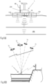
- FIG. 6(A) shows a front view of the small-scale crewless catamaran.
- FIG. 6(B) shows a state where the measurement site's latitude/longitude information is acquired.
- the solid lines indicate the ultrasonic waves transmitted from the transmitter/receiver
- the dotted lines indicate the surface reflected waves from the sludge layer surface and bottom surface
- the one-dot chain lines indicate the secondary waves reflected from the bottom surface of the ship.
- the small-scale crewless catamaran 200 is equipped with at least drive means (the drawing is omitted) and an ultrasonic transmitter/receiver 10.
- the receipt information received by the transmitter/receiver 10 may be transmitted to a base station on the ground by a communication means 90 or may be stored in a storage means such as a RAM provided in the small-scale crewless catamaran 200.
- the small-scale crewless catamaran may be driven while confirming the acquired receipt information by displaying it on a monitor serving as a display means. If the state of the sludge layer is surveyed while checking the receipt information, it is preferable since even the case where an abnormal value occurs can be responded to quickly.
- the obtained information is transmitted to the base facility through the communication means 90 and displayed on the monitor, it is superior in that making contrast by comparing it with other accumulated states of sludge layers can be possible.
- extending the cruising distance of making measurements is preferable by not loading a monitor or an analysis means, etc., on the small-scale crewless catamaran.
- the small-scale crewless catamaran 200 is operated by the radio control device while being checked by an operator (refer to FIG. 6 ).
- the small-scale crewless catamaran is a ship in which two fuselages 110 are connected in parallel with the deck, and between both fuselages is a central part space.
- the deck of the central part space of the fuselages is open, and the transmitter/receiver 10 is hung down from the central part space so as to be in contact with the water surface.
- the ultrasonic waves transmitted from the transmitter/receiver are directed to the sludge layer directly below and reflected on the surface and bottom surface of the sludge layer.
- the bottom surfaces of the fuselages 110 are made substantially flat, and the reflection occurs on the bottom surfaces.
- the small-scale crewless catamaran 200 is made small so that it can be used for measuring the sludge thickness of a reservoir of the inland region, and it is possible to be mounted on a vehicle and transported.
- the total length of the ship and the width of both fuselages are preferably both within about 1.0 m, but the size is not limited.
- the GPS positioning device 70 acquires latitude/longitude information from at least four artificial satellites 71 and obtains the latitude/longitude information with high accuracy (refer to FIG. 6(B) ). More specifically, acquiring latitude/longitude information from the centimeter-level positioning augmentation service by the quasi-zenith satellite system provided by the Cabinet Office Space Development Strategy Promotion Secretariat is preferable.
- the small-scale crewless catamaran 200 may be automatically navigated by inputting the coordinates of the measuring site in advance, and also, it is obvious that a function for correcting the navigating position may be provided in the case the difference between the coordinates of the measuring site and the acquired latitude/longitude information exceeds a predetermined range.
- a function for correcting the navigating position may be provided in the case the difference between the coordinates of the measuring site and the acquired latitude/longitude information exceeds a predetermined range.
Landscapes
- Physics & Mathematics (AREA)
- Engineering & Computer Science (AREA)
- Remote Sensing (AREA)
- General Physics & Mathematics (AREA)
- Radar, Positioning & Navigation (AREA)
- Computer Networks & Wireless Communication (AREA)
- Acoustics & Sound (AREA)
- Thermal Sciences (AREA)
- Fluid Mechanics (AREA)
- Electromagnetism (AREA)
- Life Sciences & Earth Sciences (AREA)
- Hydrology & Water Resources (AREA)
- Length Measuring Devices Characterised By Use Of Acoustic Means (AREA)
- Measurement Of Levels Of Liquids Or Fluent Solid Materials (AREA)
- Measurement Of Velocity Or Position Using Acoustic Or Ultrasonic Waves (AREA)
Applications Claiming Priority (2)
| Application Number | Priority Date | Filing Date | Title |
|---|---|---|---|
| JP2022038910A JP7188717B1 (ja) | 2022-03-14 | 2022-03-14 | ヘドロ厚測定方法およびヘドロ厚測定装置 |
| PCT/JP2022/046325 WO2023176072A1 (ja) | 2022-03-14 | 2022-12-16 | ヘドロ厚測定方法およびヘドロ厚測定装置 |
Publications (2)
| Publication Number | Publication Date |
|---|---|
| EP4495543A1 true EP4495543A1 (de) | 2025-01-22 |
| EP4495543A4 EP4495543A4 (de) | 2026-01-07 |
Family
ID=84441479
Family Applications (1)
| Application Number | Title | Priority Date | Filing Date |
|---|---|---|---|
| EP22896824.4A Pending EP4495543A4 (de) | 2022-03-14 | 2022-12-16 | Schlammdickenmessverfahren und schlammdickenmessvorrichtung |
Country Status (3)
| Country | Link |
|---|---|
| EP (1) | EP4495543A4 (de) |
| JP (1) | JP7188717B1 (de) |
| WO (1) | WO2023176072A1 (de) |
Families Citing this family (2)
| Publication number | Priority date | Publication date | Assignee | Title |
|---|---|---|---|---|
| JP7690715B1 (ja) * | 2024-12-17 | 2025-06-11 | 国土交通省国土技術政策総合研究所長 | 測量システム及び河川測量方法 |
| JP7755116B1 (ja) * | 2025-07-19 | 2025-10-16 | 国土交通省国土技術政策総合研究所長 | 測量システム及び河川測量方法 |
Family Cites Families (11)
| Publication number | Priority date | Publication date | Assignee | Title |
|---|---|---|---|---|
| JPS604955B2 (ja) * | 1977-01-21 | 1985-02-07 | 海上電機株式会社 | ヘドロ浚渫用音響探査装置 |
| JPS5786043A (en) * | 1980-11-18 | 1982-05-28 | Oki Electric Ind Co Ltd | Sludge searcher |
| JPS59147257A (ja) * | 1983-02-14 | 1984-08-23 | Oki Electric Ind Co Ltd | ヘドロ探査機 |
| JPS6085381A (ja) | 1983-10-17 | 1985-05-14 | Oki Electric Ind Co Ltd | ヘドロ探査機 |
| JPS60192281A (ja) | 1984-03-13 | 1985-09-30 | Oki Electric Ind Co Ltd | ヘドロ探査機 |
| US4780858A (en) * | 1986-12-29 | 1988-10-25 | Shell Oil Company | Borehole televiewer mudcake monitor |
| JP3259544B2 (ja) * | 1994-10-05 | 2002-02-25 | 日本電信電話株式会社 | 海底埋設物の探査方法および装置 |
| JP3590833B2 (ja) * | 1997-04-21 | 2004-11-17 | 独立行政法人農業工学研究所 | 測量システムとその測量システムを用いた測量方法 |
| JP2000193747A (ja) | 1998-12-29 | 2000-07-14 | Honda Electronic Co Ltd | 魚群探知機 |
| JP3202969B2 (ja) * | 1999-02-19 | 2001-08-27 | 富士通株式会社 | 波動受信装置 |
| KR102322776B1 (ko) | 2010-02-18 | 2021-11-04 | 마우이 이미징, 인코포레이티드 | 초음파 이미지를 구성하는 방법 및 이를 위한 다중-개구 초음파 이미징 시스템 |
-
2022
- 2022-03-14 JP JP2022038910A patent/JP7188717B1/ja active Active
- 2022-12-16 WO PCT/JP2022/046325 patent/WO2023176072A1/ja not_active Ceased
- 2022-12-16 EP EP22896824.4A patent/EP4495543A4/de active Pending
Also Published As
| Publication number | Publication date |
|---|---|
| WO2023176072A1 (ja) | 2023-09-21 |
| JP7188717B1 (ja) | 2022-12-13 |
| JP2023133749A (ja) | 2023-09-27 |
| EP4495543A4 (de) | 2026-01-07 |
Similar Documents
| Publication | Publication Date | Title |
|---|---|---|
| EP4495543A1 (de) | Schlammdickenmessverfahren und schlammdickenmessvorrichtung | |
| KR101714542B1 (ko) | 초음파에 의한 파랑계측방법 및 파랑계측 시스템 | |
| JP3658595B2 (ja) | Gps式波高・流向流速計測装置及びgps式波高・流向流速計測システム | |
| US7728759B2 (en) | System and method for using iridium satellite signals for meteorological measurements | |
| US20120327741A1 (en) | Data collection system, marine seismic survey system and method of estimating a corrected sound speed | |
| Wright et al. | Depth calibration and validation of the experimental advanced airborne research lidar, EAARL-B | |
| CN102081170A (zh) | 基于声学长基线和超短基线组合定位的海底电缆二次定位方法 | |
| KR20110026335A (ko) | 운항선박을 이용한 실시간 수질 모니터링 시스템 | |
| KR101339678B1 (ko) | 갯녹음 실태조사를 위한 암반,비암반 면적 산출방법 | |
| Bouin et al. | A kinematic GPS methodology for sea surface mapping, Vanuatu | |
| US7447112B2 (en) | Test method for a method for passively obtaining target parameters | |
| JP7723962B2 (ja) | 水中航走体の音響測位処理方法、音響測位処理プログラム、及び音響測位処理システム | |
| Furukawa et al. | Verification of GNSS multipath and positioning in urban areas using 3D maps | |
| TW202303185A (zh) | 電離層前兆地震參數短期預報方法 | |
| RU2282217C1 (ru) | Способ определения комплексных данных о состоянии океана | |
| Shin et al. | Application of broadcast RTK for automated static correction in 3D sub-bottom profiling | |
| JP2012211795A (ja) | 海面における中周期波の計測方法および計測装置 | |
| Hines et al. | Acoustic backscatter measurements from littoral seabeds at shallow grazing angles at 4 and 8 kHz | |
| Ochin | Spoofing detection for underwater acoustic GNSS-like positioning systems | |
| Doutt et al. | Using GPS at sea to determine the range between a moving ship and a drifting buoy to centimeter-level accuracy | |
| Gardner | Cruise Report RV Inland Surveyer Cruise IS-98: The Bathymetry of Lake Tahoe, California-Nevada, August 2 Through August 17, 1998, Lake Tahoe, California and Nevada | |
| Voulgaris et al. | USP RoxAnn ground discrimination system: a preliminary evaluation | |
| Thornton et al. | The development of an acoustic probe to measure the thickness of ferro-manganese crusts | |
| Guimaraes | Obtaining a reference for calibrating broadband multibeam seabed backscatter | |
| Chuku et al. | Seafloor Sediments Morphodynamics: Implications on Subsea Facilities in Mfotu field offshore Eastern Niger Delta Nigeria |
Legal Events
| Date | Code | Title | Description |
|---|---|---|---|
| STAA | Information on the status of an ep patent application or granted ep patent |
Free format text: STATUS: UNKNOWN |
|
| STAA | Information on the status of an ep patent application or granted ep patent |
Free format text: STATUS: THE INTERNATIONAL PUBLICATION HAS BEEN MADE |
|
| PUAI | Public reference made under article 153(3) epc to a published international application that has entered the european phase |
Free format text: ORIGINAL CODE: 0009012 |
|
| STAA | Information on the status of an ep patent application or granted ep patent |
Free format text: STATUS: REQUEST FOR EXAMINATION WAS MADE |
|
| 17P | Request for examination filed |
Effective date: 20230531 |
|
| AK | Designated contracting states |
Kind code of ref document: A1 Designated state(s): AL AT BE BG CH CY CZ DE DK EE ES FI FR GB GR HR HU IE IS IT LI LT LU LV MC ME MK MT NL NO PL PT RO RS SE SI SK SM TR |
|
| DAV | Request for validation of the european patent (deleted) | ||
| DAX | Request for extension of the european patent (deleted) | ||
| A4 | Supplementary search report drawn up and despatched |
Effective date: 20251209 |
|
| RIC1 | Information provided on ipc code assigned before grant |
Ipc: G01B 17/02 20060101AFI20251203BHEP Ipc: G01C 13/00 20060101ALI20251203BHEP Ipc: G01S 7/62 20060101ALI20251203BHEP Ipc: G01F 23/2962 20220101ALI20251203BHEP Ipc: G01S 15/88 20060101ALI20251203BHEP |
|
| RAP3 | Party data changed (applicant data changed or rights of an application transferred) |
Owner name: JINZAIKAIHATSU-SIENKIKOU CO., LTD. |