EP4495562A1 - Dispositif et système de mesure d'un paramètre physique relatif à la chaussée d'une section d'infrastructure routière - Google Patents
Dispositif et système de mesure d'un paramètre physique relatif à la chaussée d'une section d'infrastructure routière Download PDFInfo
- Publication number
- EP4495562A1 EP4495562A1 EP24186754.8A EP24186754A EP4495562A1 EP 4495562 A1 EP4495562 A1 EP 4495562A1 EP 24186754 A EP24186754 A EP 24186754A EP 4495562 A1 EP4495562 A1 EP 4495562A1
- Authority
- EP
- European Patent Office
- Prior art keywords
- pavement
- radio signal
- measuring device
- wake
- measuring
- Prior art date
- Legal status (The legal status is an assumption and is not a legal conclusion. Google has not performed a legal analysis and makes no representation as to the accuracy of the status listed.)
- Pending
Links
Images


Classifications
-
- G—PHYSICS
- G01—MEASURING; TESTING
- G01K—MEASURING TEMPERATURE; MEASURING QUANTITY OF HEAT; THERMALLY-SENSITIVE ELEMENTS NOT OTHERWISE PROVIDED FOR
- G01K1/00—Details of thermometers not specially adapted for particular types of thermometer
- G01K1/02—Means for indicating or recording specially adapted for thermometers
- G01K1/024—Means for indicating or recording specially adapted for thermometers for remote indication
-
- E—FIXED CONSTRUCTIONS
- E01—CONSTRUCTION OF ROADS, RAILWAYS, OR BRIDGES
- E01C—CONSTRUCTION OF, OR SURFACES FOR, ROADS, SPORTS GROUNDS, OR THE LIKE; MACHINES OR AUXILIARY TOOLS FOR CONSTRUCTION OR REPAIR
- E01C23/00—Auxiliary devices or arrangements for constructing, repairing, reconditioning, or taking-up road or like surfaces
- E01C23/01—Devices or auxiliary means for setting-out or checking the configuration of new surfacing, e.g. templates, screed or reference line supports; Applications of apparatus for measuring, indicating, or recording the surface configuration of existing surfacing, e.g. profilographs
-
- E—FIXED CONSTRUCTIONS
- E01—CONSTRUCTION OF ROADS, RAILWAYS, OR BRIDGES
- E01F—ADDITIONAL WORK, SUCH AS EQUIPPING ROADS OR THE CONSTRUCTION OF PLATFORMS, HELICOPTER LANDING STAGES, SIGNS, SNOW FENCES, OR THE LIKE
- E01F11/00—Road engineering aspects of Embedding pads or other sensitive devices in paving or other road surfaces, e.g. traffic detectors, vehicle-operated pressure-sensitive actuators, devices for monitoring atmospheric or road conditions
-
- G—PHYSICS
- G01—MEASURING; TESTING
- G01K—MEASURING TEMPERATURE; MEASURING QUANTITY OF HEAT; THERMALLY-SENSITIVE ELEMENTS NOT OTHERWISE PROVIDED FOR
- G01K13/00—Thermometers specially adapted for specific purposes
- G01K13/10—Thermometers specially adapted for specific purposes for measuring temperature within piled or stacked materials
Definitions
- the present invention relates in general to the field of devices and systems for the construction, monitoring and maintenance of road infrastructures.
- the present invention relates to a device for measuring a physical parameter relating to the pavement of a road infrastructure section.
- the present invention also relates to a system for measuring a physical parameter relating to the pavement of a road infrastructure section comprising said device.
- the pavement of road infrastructures in general is made from asphalt concrete which, as known, is a visco-elastic plastic material comprising a mixture of aggregates (rock material of various particle sizes, such as filler, sand and gravel) and a bituminous binder.
- asphalt concrete which, as known, is a visco-elastic plastic material comprising a mixture of aggregates (rock material of various particle sizes, such as filler, sand and gravel) and a bituminous binder.
- the pavement comprises various layers of asphalt concrete, which are laid one over the other until a total thickness of the pavement typically comprised between 25 cm and 40 cm is reached.
- WO 2013/082109 describes a method for control of the pavement laying process, in which it is provided for the temperature sensors to be mixed with the pavement material and therefore laid with it. It is also provided for a wireless signal emitted by the temperature sensors to be monitored during the laying process, and for the laying process parameters to be adjusted on the basis of the wireless signal received.
- WO 2013/082109 i.e. control of the pavement laying process
- the temperature sensors of WO 2013/082109 may therefore be powered with respective batteries, the only requirement of which, in terms of duration, is that of supporting continual transmission of the wireless signal for some hours.
- the bearing capacity of the pavement is generally measured by means of a deflectometer.
- the deflectometer applies a load to a certain position of the pavement, which therefore deflects, forming a deflection basin.
- the deflectometer therefore measures the profile of the deflection basin (for example, by means of geophones or laser Doppler sensors), and obtains information on the bearing capacity of the pavement.
- a curvature index of the deflection basin can be measured (SCI, or "Surface Curvature Index”), on the basis of which an estimate of the residual useful lifetime of the pavement can be calculated, a parameter that allows planning of replacement and/or maintenance interventions.
- deflectometers such as FWD, or Falling Weight Deflectometers
- impact deflectometers such as FWD, or Falling Weight Deflectometers
- FWD flight speed detector
- TSD Traffic Speed Deflectometer
- the Applicant has noticed that a detection of the temperature of the pavement would allow the result provided by the deflectometer (for example, the SCI) to be normalized with respect to a reference temperature, for example 20°C, in order to take account of the effective temperature of the pavement in the position and time at which the deflectometer provides the results.
- a reference temperature for example 20°C
- the Applicant has observed that, for this purpose, it would be advantageous to use temperature sensors installed in the pavement, possibly at a distance of at least 10 cm from the surface of the pavement. Measurement of the pavement temperature at this depth is indeed more repeatable and stable with respect to, for example, a measurement of the temperature of the surface of the pavement, a parameter that is subject to high variability, due to factors such as irradiation, wind or rain to which the pavement surface is exposed.
- the temperature sensors it is desirable for the temperature sensors to be able to operate (i.e. to detect the temperature and to transmit it to the deflectometer) for the entire life cycle of the pavement, meaning for the entire time that passes from laying of the pavement of a road section up until its subsequent removal and the new laying of the pavement of the same road section. Said period is generally 7-10 years.
- an object of the present invention is to provide a device for measuring a physical parameter relating to the pavement of a road infrastructure section (in particular, but not exclusively, the temperature) that solves the above drawbacks.
- an object of the present invention is to provide a device for measuring a physical parameter relating to the pavement of a road infrastructure section (in particular, but not exclusively, the temperature) that is able to operate for a period of time compatible with the duration of the typical life cycle of said pavement (generally 7-10 years), so as to be installable during the pavement laying phase and to be suitable for applications that require a prolonged use of the measuring device, such as monitoring of the bearing capacity of the pavement.
- a measuring device comprising a sensor, a clock unit, a radio transceiver and a processor.
- the measuring device is operated cyclically in a sleeping mode for a period of a first predefined duration T1 and in a listening mode for a period of a second maximum predefined duration T2.
- sleeping mode only the clock unit is switched on for counting the first predefined duration T1, whereas in listening mode the radio transceiver and the processor are also switched on.
- the processor acquires, by means of the sensor, a measurement of the physical parameter relating to the pavement at the position of the measuring device and, by means of the radio transceiver, transmits the acquired measurement via radio.
- the measuring device is capable of operating for a period of time compatible with the duration of the typical life cycle of said pavement (generally 7-10 years), and is therefore installable in the pavement laying phase and suitable for applications that require a prolonged use of the measuring device, such as for example monitoring of the bearing capacity of the pavement.
- the measuring device does not detect any wake-up radio signal, indeed, it continues to cyclically alternate periods of duration T1, in which it is in sleeping mode, and periods of duration T2, in which it is in listening mode.
- the wake-up radio signal is received with a low frequency (for example, 1 or 2 times per year, if the measuring device is used for monitoring the bearing capacity of the pavement)
- acquisition of the measurement of the physical parameter relating to the pavement and its transmission via radio are a rare event, which has an almost irrelevant impact on energy consumption by the measuring device. Therefore, since the energy consumption of the device in sleeping mode is extremely limited (typically in the order of several ⁇ A), the parameter that most greatly impacts on the energy consumption of the measuring device is the frequency with which the measuring device exits from sleeping mode and enters into listening mode.
- Said frequency depends, in turn, on the duty cycle of the measuring device, defined as the ratio between predefined duration T1 and maximum predefined duration T2.
- the greater the duty cycle i.e. the greater duration T1 is with respect to duration T2
- the greater the duty cycle the lower the reactivity of the measuring device, i.e. the longer the time that the measuring device takes to react to a wake-up radio signal.
- the Applicant has estimated that this value of the duty cycle allows the measuring device to be operational for a period of 7-10 years. This is obtained together with a reactivity of the measuring device that is acceptable for applications such as monitoring the bearing capacity.
- T1 and T2 a measuring device is therefore obtained that is capable of operating throughout the typical life cycle of the pavement, and that may therefore be installed in the pavement laying phase and be used for monitoring the bearing capacity throughout the life cycle of the pavement.
- a measuring device for measuring a physical parameter relating to the pavement of a road infrastructure section, the measuring device comprising a sensor, a clock unit, a radio transceiver and a processor, wherein:
- the senor is a temperature sensor suitable for acquiring at least one measurement of the temperature of a portion of the pavement adjacent to the measurement device.
- the measuring device also comprises a battery electrically connected to the sensor, to the clock unit, to the radio transceiver and to the processor, so as to supply electrical power to them.
- the measuring device also comprises a casing suitable for containing the sensor, the clock unit, the radio transceiver and the processor, wherein the casing comprises:
- the plastic material comprises chlorinated polyvinyl chloride and the resin comprises an epoxy resin.
- the ratio between the first predefined duration T1 and the second maximum predefined duration T2 is comprised between 100 and 200.
- the processor is configured to, in listening mode:
- the present invention relates to a system for measuring a physical parameter relating to the pavement of a road infrastructure section, the system comprising:
- At least one of the plurality of measuring devices is suitable for being located at a depth D with respect to the surface of the pavement, the depth D being greater than 5 cm.
- the respective positions of the measuring devices are substantially equally spaced by a distance L comprised between 100 m and 500 m.
- control device comprises a geographic position sensor and a memory which stores, for each measuring device, data indicative of the geographic position of the measuring device, the control device being configured to:
- control device is configured to:
- the system also comprises a deflectometer movable along the road infrastructure section substantially integral with the control device, the deflectometer being configured to, while moving along the road infrastructure section integrally with the control device, acquire data indicative of the bearing capacity of the pavement of the road infrastructure section.
- the present invention provides a method for measuring a physical parameter relating to the pavement of a road infrastructure section, the method comprising:
- Figure 1 shows a device for measuring a physical parameter relating to the pavement of a road infrastructure section, such as for example a road or motorway section.
- the measuring device 1 is suitable for being installed inside the pavement 2, as shown in Figure 2 .
- the pavement 2 comprises a plurality of layers of asphalt concrete, laid one over the other until a total thickness H of the pavement 2 preferably comprised between 25 cm and 40 cm is reached.
- the measuring device 1 is suitable for being installed in the pavement 2 during the laying process of the pavement itself.
- the measuring device 1, when installed, is located at a depth D with respect to the surface 2a of the pavement 2, where depth D means the distance between the surface 2a of the pavement 2 and the base of the measuring device 1, as schematically indicated in Figure 2 .
- the depth D is preferably greater than 5 cm, more preferably greater than 10 cm, for example 15 cm.
- the measuring device 1 comprises a sensor 10 suitable for acquiring at least one measurement of a physical parameter (for example, but not exclusively, the temperature) relating to the pavement 2 at the position of the measuring device 1.
- the sensor 10 may be a temperature sensor suitable for acquiring at least one measurement of the temperature of the portion of the pavement adjacent to the measurement device 1.
- the temperature sensor 10 is suitable for acquiring at least one measurement of the temperature at the base of the measuring device 1.
- a copper sheet (not shown in the drawing) that extends across the base of the device 1 may be fixed (for example with a thermally conductive tape or paste) onto the temperature sensor 10.
- the temperature sensor 10 preferably has a measurement range comprised between -10°C and +60°C.
- the temperature sensor 10 also preferably has an accuracy greater than or equal to 1/10 °C.
- the Applicant has performed several positive tests using the temperature sensor model TMP117 manufactured and marketed by the company Texas Instruments Inc., with head office in Dallas (Texas, US).
- the measuring device 1 also preferably comprises a clock unit 11 configured to count a period of predefined duration T1, as will be discussed in further detail here below.
- the measuring device 1 also preferably comprises a radio transceiver 12.
- the radio transceiver 12 may, for example, operate in a band below 1 GHz (frequencies under GHz) without licenses. Furthermore, the radio transceiver 12 may use LoRa (Long Range) modulation, or FSK (Frequency-Shift Keying) modulation.
- LoRa Long Range
- FSK Frequency-Shift Keying
- the measuring device 1 also preferably comprises a processor 13 connected to the sensor 10 and to the radio transceiver 12, so as to coordinate their operation.
- the processor 13 may be made as a single component, or with two or more components connected to and cooperating with each other.
- the measuring device 1 preferably also comprises a battery 14.
- the battery 14 is preferably electrically connected (through an electrical circuit, not shown in Figure 1 ) to the sensor 10, to the clock unit 11, to the radio transceiver 12 and to the processor 13, so as to supply electrical power to these components.
- the battery 14, for example, may be a 3.6 V and 2.4 Ah lithium thionyl chloride battery.
- the sensor 10, the clock unit 11, the radio transceiver 12, the processor 13 and the battery 14 are preferably mounted on a PCB (Printed Circuit Board) 16, shown in Figures 3a, 3b and 3c (in Figures 3a, 3b and 3c , in order not to overload the drawings, only the battery 14 is shown, whereas the sensor 10, the clock unit 11, the radio transceiver 12 and the processor 13 are not shown).
- PCB Print Circuit Board
- the measuring device 1 also comprises a casing 15 suitable for containing all the other components of the measuring device 1.
- the structure and material(s) of the casing 15 are preferably chosen in a manner to resist the conditions (in particular, temperature, pressure, vibrations and mechanical stresses) to which the measuring device 1 is subjected during the laying process of the pavement 2.
- the temperature during laying of the pavement 2 in particular, may reach 150°.
- FIGS 3a, 3b and 3c show the casing 15 according to an embodiment of the present invention.
- the casing comprises a tubular body 15a inside which the sensor 10, the clock unit 11, the radio transceiver 12, the processor 13 and the battery 14 are housed.
- the tubular body 15a is preferably made in a plastic material.
- the tubular body 15a may be in PVC-C (chlorinated polyvinyl chloride).
- the diameter of the tubular body 15a is preferably comprised between 20 mm and 30 mm, for example 25 mm.
- the length of the tubular body 15a is preferably comprised between 70 mm and 90 mm, for example 80 mm.
- the tubular body 15a is preferably encased inside a block of resin 15b.
- the block of resin 15b is preferably formed around the tubular body 15a by means of a resining process of the tubular body 15a.
- a silicon mould is preferably used for forming of the block of resin 15b.
- the tubular body 15a is preferably sealed at its ends, for example by means of rubber caps or impermeable adhesive films, in order to prevent the resin from entering into contact with the components of the measuring device 1, in particular with the antenna of the radio transceiver 12.
- the block in resin 15b is preferably in epoxy resin.
- the epoxy resin preferably has a temperature range comprised between -50°C and +150°C, a permittivity at 10 Hz equal to 4.7 ⁇ 20% and a Shore hardness comprised between D45 and D60.
- the Applicant has performed positive tests using the ER1448 epoxy resin manufactured and marketed by the company Electrolube, with head office in Woking (Surrey, U K).
- the block of resin 15b preferably has a quadrangular prism shape, preferably with rounded edges.
- the length of the block of resin 15b (where "length” means its dimension in the direction parallel to the axis of the tubular body 15a) is preferably comprised between 100 mm and 120 mm, for example 110 mm.
- the block of resin 15b Perpendicularly to the axis of the tubular body 15a, the block of resin 15b has a height preferably comprised between 30 mm and 50 mm, for example 40 mm; and a width preferably comprised between 60 mm and 80 mm, for example 70 mm.
- the measuring device 1 is operated in a sleeping mode (step 401) and in a listening mode (step 402) cyclically and alternately.
- the clock unit 11 In sleeping mode, only the clock unit 11 is switched on. All the other components of the measuring device 1 are switched off, so that it is not able either to transmit or to receive radio signals. Since the clock unit 11 has an extremely limited energy consumption (typically in the order of several ⁇ A), the energy consumption of the measuring device 1 in sleeping mode is therefore extremely limited. At each iteration of step 401, the measuring device 1 remains in sleeping mode for a period of time having predefined duration T1, counted by the clock unit 11.
- the clock unit 11 Upon expiry of T1, the clock unit 11 sends an electric signal to the radio transceiver 12 and to the processor 13. The electric signal switches on the radio transceiver 12 and the processor 13, so that the measuring device 1 enters into the listening mode. In listening mode, the measuring device 1 is therefore able to receive radio signals.
- the measuring device 1 starts listening for any wake-up radio signals through the radio transceiver 12.
- the measuring device 1 remains in listening mode for a period of time having maximum predefined duration T2.
- the processor 13 determines that through the radio transceiver 12 no wake-up radio signal has been received (step 403), it preferably returns the measuring device 1 into sleeping mode (step 401), switching off itself and the radio transceiver 12.
- the processor 13 determines that through the radio transceiver 12 a wake-up radio signal has been received, it preferably acquires through the sensor 10 a measurement of a physical parameter relating to the pavement 2 (step 404).
- the processor 13 preferably transmits via radio the measurement acquired through the radio transceiver 12 (step 405).
- the processor 13 preferably returns the measuring device 1 into sleeping mode (step 401), switching off itself and the radio transceiver 12.
- the cyclic and alternating iteration of steps 401 and 402 therefore starts again, until a new wake-up radio signal is received.
- the operation of the measuring device 1 described above continues for as long as the components of the measuring device 1 are able to operate, i.e. until complete discharging of the battery 14.
- the measuring device 1 is capable of operating for a period of time compatible with the period of the typical life cycle of the pavement (generally 7-10 years), and can therefore be installed in the pavement 2 laying phase and be used for applications that require a prolonged use of the measuring device 1, such as the aforesaid monitoring of the bearing capacity of the pavement.
- the measuring device 1 does not detect any wake-up radio signal, indeed, it continues to alternate cyclically periods of duration T1, in which it is in sleeping mode, and periods of duration T2, in which it is in listening mode.
- the wake-up radio signal is received with a low frequency (for example, 1 or 2 times per year, if the measuring device is used for monitoring the bearing capacity of the pavement)
- acquisition of the measurement of the physical parameter relating to the pavement 2 (step 404) and its transmission via radio (step 405) are a rare event, which has an almost irrelevant impact on energy consumption by the measuring device 1. Therefore, since the energy consumption of the measuring device 1 in sleeping mode is extremely limited (typically in the order of several ⁇ A, i.e.
- the parameter that most greatly impacts on the energy consumption of the measuring device 1 is the frequency with which the measuring device 1 exits from sleeping mode and enters into listening mode. Said frequency depends in turn on the duty cycle of the measuring device 1, defined as the ratio between duration T1 and duration T2.
- the greater the duty cycle i.e. the greater duration T1 with respect to duration T2 is), the lower the frequency with which the measuring device 1 enters into listening mode, and therefore the lower its overall energy consumption.
- the greater the duty cycle the lower the reactivity of the measuring device 1, i.e. the longer the time that the measuring device 1 takes to react to a wake-up radio signal.
- duty cycle T1/T2 it is therefore possible to find an appropriate trade-off between energy consumption of the measuring device 1 (and, therefore, the duration of the period for which the measuring device is operational) and the reactivity of the device 1 itself, choosing the value of duty cycle T1/T2 accordingly. Where low energy consumption is important, whereas a lower reactivity is acceptable, a higher duty cycle T1/T2 may be chosen. If, on the other hand, an application requires a higher reactivity, a lower duty cycle T1/T2 may be chosen.
- Step 403 of detecting the wake-up radio signal will be described in further detail below.
- the radio transceiver 12 is configured to receive and transmit radio signals, whose format is schematically shown in Figure 5 .
- the radio signal (indicated with reference number 5) preferably comprises a plurality of fields, including a preamble 50, a synchronization word 51 and a payload 52.
- the payload 52 may comprise an identifier ID(1) of the measuring device 1. If, on the other hand, the radio signal 5 is a wake-up radio signal transmitted in broadcasting mode to several identical devices to the measuring device 1, the payload 52 may comprise a predefined value that indicates the broadcasting transmission mode.
- the radio signal 5 may be, for example, an FSK signal.
- the preamble 50 comprises 7,625 symbols
- the synchronization word 51 comprises 3 bytes
- the payload 52 comprises 8 bytes.
- a Length field of 1 byte and a CRC field of 2 bytes are also present.
- the measuring device 1 in listening mode the measuring device 1 (in particular, the processor 13) preferably remains in listening mode for any radio signals comprising a sequence of symbols corresponding with the preamble 50.
- the processor 13 determines that through the radio transceiver 12 no wake-up radio signal comprising a sequence of symbols corresponding with the preamble 50 has been received, it preferably returns the device 1 into sleeping mode (step 401).
- the processor 13 determines that through the radio transceiver 12 a wake-up radio signal comprising a sequence of symbols corresponding with the preamble 50 has been received, it preferably determines whether this is followed by a sequence of bytes corresponding with the synchronization word 51. This check allows the processor 13 to establish whether the radio signal received actually is a radio signal having the expected format (i.e. identical to the radio signal 5) or whether it is noise, i.e. a radio signal that only accidentally comprises a sequence of symbols corresponding with the preamble 50.
- the processor 13 preferably compares the sequence of bytes (8 bytes, in the case of an FSK signal) that follows the sequence of symbols corresponding with the preamble 50 in the radio signal received with the synchronization word 51 locally stored by the measuring device 1.
- the processor 13 concludes that the radio signal received is noise, and therefore returns to sleeping mode (step 401). If, on the other hand, they coincide, the processor 13 preferably determines that it is actually a radio signal having the expected format (i.e. identical to the one of the radio signal 5), and therefore reads its payload.
- the processor 13 preferably concludes that the radio signal received is actually a wake-up radio signal destined for the measuring device 1. It therefore performs steps 404 (acquisition of a measurement of a physical parameter relating to the pavement 2 by means of the sensor 10) and 405 (transmission via radio of the measurement acquired by means of the radio transceiver 12).
- the processor 13 may send to the sensor 10 a trigger signal that starts the acquisition of the measurement. While the measurement is being performed, the processor 13 may be partially disabled, leaving enabled only an internal timer (not shown in the drawings) that counts a period of predefined duration T3.
- the duration T3 is preferably comprised between 100 ms and 200 ms, for example it may be 160 ms.
- the processor 13 preferably transmits via radio through the radio transceiver 12 a response radio signal, whose format is also identical to the format of the radio signal 5 shown in Figure 5 .
- the measurement of the physical parameter relating to the pavement 2 acquired by the sensor 10 is inserted into the payload of the response radio signal, preferably together with the identifier ID(1) of the measuring device 1.
- the processor 13 may wait for a timeslot assigned to it to transmit the response radio signal by means of the radio transceiver 12.
- the processor 13 preferably ignores the radio signal received and returns the measuring device 1 to the sleeping mode (step 401).
- Figure 6a schematically shows operation of the measuring device 1 according to the embodiment just described, in the case in which no wake-up radio signal is received.
- T1 and T2 may be, for example, 1200 ms and 8 ms respectively.
- Figure 6b schematically shows operation of the measuring device 1 according to the embodiment just described, in the case in which a wake-up radio signal is received.
- the check on the synchronization word and reading of the payload begins, which step terminates at time t3 and may have a duration t3-t2 for example of about 1225 ms.
- the measuring device 1 preferably transmits the response radio signal, which step terminates at time t5 and may have a duration of about 5 ms.
- the measuring device 1 returns to alternating the sleeping mode and the listening mode in an identical manner to what is described above with reference to Figure 6a .
- the device 1 may be used for implementing a system for measuring a physical parameter relating to the pavement of a road infrastructure section.
- Figure 7 schematically shows a system 100 for measuring a physical parameter relating to the pavement of a road infrastructure section, according to an embodiment of the present invention.
- the system 100 comprises a plurality of measuring devices identical to the measuring device 1 described above.
- the measuring devices 1.1, 1.2, 1.3, 1.4, 1.5 are installed inside the pavement 2 of a road infrastructure section 3, such as, for example, a road or motorway section.
- the measuring devices 1.1, 1.2, 1.3, 1.4, 1.5 are installed during laying of the payment 2, at a depth D with respect to the surface 2a of the pavement 2.
- the measuring devices 1.1, 1.2, 1.3, 1.4, 1.5 are installed in respective positions.
- the positions of the measuring devices 1.1, 1.2, 1.3, 1.4, 1.5 are distributed along a same lane of the road infrastructure section 3, so that a vehicle 4 that is travelling in the lane (as indicated schematically by arrow A in Figure 7 ) transits by each of them.
- the positions of the measuring devices 1.1, 1.2, 1.3, 1.4, 1.5 are substantially equally spaced.
- the measuring devices 1.1, 1.2, 1.3, 1.4, 1.5 are placed at a mutual distance L comprised between 100 m and 500 m, for example 200 m.
- the system 100 also comprises at least one control device 6.
- the control device 6 is preferably movable along the road infrastructure section 3.
- the control device 6 is installable on board the aforementioned vehicle 4, which travels in a lane of the road infrastructure section 3 as indicated schematically by arrow A in Figure 7 .
- the control device 6 comprises a radio transceiver 60.
- the radio transceiver 60 preferably has a coverage range R comprised between 50 m and 150 m.
- the coverage range R of the radio transceiver 60 may be 100 m or 130 m.
- the control device 6 also preferably comprises a geographic position sensor 61.
- the geographic position sensor 61 is preferably configured to interact with a geolocation system (not shown in the drawings), such as for example a GPS (Global Positioning System), Galileo or Glonass system, in order to detect the geographic position of the control device 6.
- a geolocation system such as for example a GPS (Global Positioning System), Galileo or Glonass system, in order to detect the geographic position of the control device 6.
- the control device 6 also preferably comprises a memory 62.
- the data indicative of the geographic position POS(1.n) of each measuring device 1.n are preferably in the form of geographic coordinates (xn; yn), where xn indicates the latitude of the device 1.n and yn indicates the longitude of the device 1.n.
- the memory 62 is also preferably configured to store the measurements provided by the measuring devices 1.n.
- the control device 6 also preferably comprises a processor 63 connected to the radio transceiver 60, to the geographic position sensor 61 and to the memory 62, in order to manage and coordinate operation of these components.
- the processor 63 may be implemented as a single device, or as a set of two or more devices mutually connected and cooperating with each other.
- the control device 6 also comprises a battery 64.
- the battery 64 is preferably electrically connected (through an electrical circuit, not shown in Figure 8 ) to the radio transceiver 60, to the geographic position sensor 61 and to the processor 63, so as to supply electrical power to these components.
- the battery 64 is preferably a rechargeable battery, having a duration of some hours (for example, 16 hours).
- the battery 64 may be a 2.4 Ah lithium polymer battery.
- control device 6 may also comprise a display (not shown in the drawings) suitable for providing information on the operation of the control device 6 and of the system 100 as a whole.
- the display may also be an LCD display.
- the processor 63 preferably periodically detects the geographic position of the control device 6 through the geographic position sensor 61 (step 901).
- the detection period is preferably comprised between 0.1 sec and 2 sec, for example 1 sec.
- the speed of the vehicle 4 is preferably lower than or equal to 130 km/h.
- the processor 63 checks whether at least one of the measuring devices 1.n is close to the control device 6 (step 903). For this purpose, the processor 63 preferably compares the geographic position determined with the data indicative of the geographic position POS(1.n) of the measuring devices 1.n stored in the memory 62.
- the processor 63 preferably transmits the wake-up radio signal to the measuring device 1.n* placed in that position (step 904).
- the wake-up radio signal has an identical format to the radio signal 5 shown in Figure 5 .
- the payload 52 of the wake-up radio signal comprises the identifier ID(1.n*) of the measuring device 1.n* for which the wake-up radio signal is intended.
- the measuring device 1.n* also alternates periods of predefined duration T1 in sleeping mode with periods of maximum predefined duration T2 in listening mode.
- the measuring device 1.n* may therefore receive and respond to the wake-up radio signal as described above (acquisition of a measurement and transmission of a response radio signal containing the measurement acquired) only if the control device 6 transmits the wake-up radio signal while the measuring device 1.n* is in listening mode. If the control device 6 transmits the wake-up radio signal while the measuring device 1.n* is in sleeping mode, the measuring device 1.n* does not receive the wake-up radio signal and does not respond to it.
- the processor 63 is preferably configured to, after transmission of the wake-up radio signal in step 904, take the control device 6 into a waiting mode (step 905), in which the control device 6 waits to receive the response radio signal from the measuring device 1.n*.
- the control device 6 preferably remains in waiting mode for a period of predefined duration T4.
- the duration T4 may, for example, be comprised between 100 ms and 200 ms, for example 160 ms.
- the processor 63 determines that through the radio transceiver 60 a response radio signal has been received (step 906), it preferably reads from its payload the measurement of the physical parameter relating to the pavement 2 of the road infrastructure section 3 and stores it (step 907).
- the measurement is stored in the memory 62 of the control device 6.
- the measurement is stored together with one or more of the following data:
- the processor 63 determines that through the radio transceiver 60 no response radio signal has been received (step 906), it preferably returns to step 904, transmitting the wake-up radio signal once again. Steps 904-906 are repeated cyclically, so that several transmission attempts of the wake-up radio signal are made.
- steps 904-906 are interrupted when the processor 63 determines that through the radio transceiver 60 a response radio signal has been received (step 907), or when an interruption condition occurs (step 908).
- a first example of an interruption condition may be the reaching of a predefined number of transmission attempts of the wake-up radio signal.
- the control device 6 could exceed the geographic position of the measuring device 1.n*.
- a second example of an interruption condition could therefore be reaching by the control device 6 of a geographic position that follows the geographic position of the measuring device 1.n* in the travel direction of the vehicle 4 by more than a certain predefined distance Lmax.
- the distance Lmax may be comprised between 20 m and 50 m, for example it can be equal to 35 m.
- the number of attempts performed by the control device 6 depends on the speed at which the vehicle 4 is travelling. If, for example, the speed of the vehicle 4 is 130 km/h, corresponding with 36.1 m/s, the control device 6 has at its disposal substantially two transmission attempts of the wake-up radio signal to the measuring device 1.n*.
- the processor 63 may record in the memory 62 an indication of the fact that acquisition of the measurement by the measuring device 1.n* has not been successful.
- Operation of the control device 6 therefore returns to steps 901-902, during which the processor 63 searches for the measuring device closest to its current position in order to send a new wake-up radio signal.
- step 909 Operation of the control device is repeated until the end of the measurement session (step 909), which typically takes place when the vehicle 4 has stopped travelling on the road infrastructure section 3 in the pavement 2 of which the measuring devices 1.1, 1.2, 1.3, 1.4, 1.5 of the system 100 are installed.
- the vehicle 4 with the control device 6 installed on board must once again travel on the road infrastructure section 3. It will be possible to perform measuring sessions for as long as the measuring devices 1.1, 1.2, 1.3, 1.4, 1.5 are operational, something that, as described above, may occur for a period of time up to 10 years, thanks to alternation of sleeping mode and listening mode.
- the control device 6 may transmit the wake-up radio signal in broadcasting mode.
- the wake-up radio signal preferably comprises in its payload a predefined value, which indicates the broadcasting transmission mode and which all the measuring devices 1.1, 1.2, 1.3, 1.4, 1.5 of the system 100 are configured to recognise.
- all the measuring devices that receive the wake-up radio signal can respond to the same wake-up radio signal.
- each measuring device 1.1, 1.2, 1.3, 1.4, 1.5 is configured with a respective timeslot during which it is authorised to transmit its own response radio signal to the control device 6.
- the timeslot can be used by the measuring device for the transmission of any response radio signal, or only in the case of response radio signals transmitted in response to a wake-up radio signal in broadcasting mode.
- the broadcasting transmission mode may be used as an alternative to the transmission of a wake-up radio signal intended for a specific measuring device, or in combination with it.
- transmission in broadcasting mode can be performed when at step 902 the processor 63 determines that detection of the geographic position of the control device 6 has not been successful. This may occur, for example, when the vehicle 4 transits in a tunnel. In this case, being unable to determine the specific measuring device close to it, the processor 63 may perform a transmission of the wake-up radio signal in broadcasting mode (step 910). The processor 63 therefore reads and stores the data contained in the response radio signals received, as described above with regard to step 907.
- the system 100 could comprise two or more control devices. Each of them could be installed on board a respective vehicle and deal with acquiring the measurements from a respective set of measuring devices. For example, a first control device on board a first vehicle could detect the measurements only from the measuring devices distributed along a first portion of the road infrastructure section 3, while a second control device on board a second vehicle could detect the measurements only from the measuring devices distributed along a second portion of the road infrastructure section 3.
- the system 100 can be used for various applications.
- the system 100 could be used for monitoring the bearing capacity of the road pavement 2.
- a deflectometer (not shown in the drawings), in particular a deflectometer of the TSD type, is also fixed to the vehicle 4.
- Each bearing capacity measurement performed by the deflectometer could be acquired by the processor 63 and stored together with the geographic position of the vehicle 4 at the acquisition time and/or a timestamp that indicates the acquisition date and time.
- the measurements of bearing capacity can therefore be provided to a processor external to the control device 6, together with the temperature measurements acquired by the measuring devices 1.1, 1.2, 1.3, 1.4, 1.5.
- the measuring devices 1.1, 1.2, 1.3, 1.4, 1.5 are installed in the pavement 2 at a distance D from the surface 2a of the pavement itself, the measurement of the temperature of the pavement 2 is more repeatable and stable with respect to, for example, a measurement of the temperature of the surface 2a of the pavement 2, a parameter subject to a high variability as a result of factors such as irradiation, wind or rain to which the surface of the pavement is exposed. Normalization of the bearing capacity measurements is therefore very accurate.
- the system 100 in the case in which the sensor 10 comprised in the measuring devices 1.1, 1.2, 1.3, 1.4, 1.5 is a temperature sensor, the system 100 could be used for monitoring the cooling of the asphalt concrete just laid.
- repaving interventions are indeed performed in very limited time windows (generally no longer than 8 hours). Within these time windows, it is planned to perform installation of the work site, removal of the previous pavement, laying of the new layers in asphalt concrete (which generally takes place at a temperature of around 150° C) and removal of the work site. Between the end of laying of the new layers of asphalt concrete and reopening to traffic, it is generally necessary to wait up to 3 hours to allow cooling of the pavement. This time period is variable as a function of certain factors, such as for example the thickness of the layers laid, the external temperature, the relative humidity and the thermal inertia of the road body.
- a measurement of the surface of the new pavement is not very indicative in this sense, since the surface, being in contact with the air, cools more quickly than the internal layers. In general, therefore, there is a tendency to overestimate the cooling time, for reasons of safety. A premature reopening of the road infrastructure section could cause immediate plastic deformations of the pavement just laid, which could represent a risk for travel.
- the system 100 allows instead determining the temperature inside the pavement 2 just laid, and therefore allows a precise determination of the moment at which it is possible to reopen the road infrastructure section 3 to traffic safely, thereby optimising both the duration of the work site activities and their impact on traffic.
- the casing 15 of the measuring device 1 (and of each measuring device 1.n of the system 100) is configured to resist the conditions (in particular, temperature, pressure, vibrations and mechanical stresses) to which the measuring device is subjected during the laying process of the pavement 2.
- the casing 15 comprises a tubular body 15a in a plastic material (inside which the sensor 10, the clock unit 11, the radio transceiver 12 and the processor 13 are housed) and a block of resin 15b which encases the tubular body 15a.
- the Applicant has made some positive tests showing that the casing with the above structure is actually capable of resisting the conditions (in particular, temperature, pressure, vibrations and mechanical stresses) to which the measuring device is subjected during the laying process of the pavement 2.
- the results of such tests are shown in Figures 10a, 10b and 10c .
- Figure 10a shows the results of a laboratory test.
- the laboratory test was conducted as follows:
- the range As to the range, a maximum value of 300 m was measured. In any case, the value of the range was above 100 m during the whole observation period.
- Figure 10a shows a graph of the variation of the detected temperature values during the observation period.
- the graph shows that, during a first period of about 45 minutes, the sensor gradually reached a thermal equilibrium with the surrounding asphalt concrete. Upon reaching the thermal equilibrium, the detected temperature reached its maximum value. Starting from this point, all the readings of the detected temperature value coincided with the actual temperature of the asphalt concrete, which was slowly cooling down.
- Figure 10b shows the results of a field test.
- the field test was conducted during an intervention for replacing the pavement of a road section.
- the intervention provided for removing a layer of 19 cm of the pre-existing pavement by milling, and then laying a new pavement made of a double layer of asphalt concrete, composed by a 15 cm base course and a 4 cm open graded asphalt concrete.
- the new pavement was laid by the known technic HMA (Hot mix Asphalt) and compacted by rolling in a known way.
- technic HMA Hot mix Asphalt
- the measuring device was placed on the ground after the milling, and then the new pavement was laid and compacted on top of it. Then, operation of the measuring device was monitored for an observation period of about 5 hours, by performing subsequent readings of the temperature value detected by its sensor. A final reading of the temperature value was also performed after about 14 hours.
- Figure 10b shows a graph of the variation of the detected temperature values during the observation period.
- the variation was similar to that shown in Figure 10a , namely during a first period the sensor gradually reached a thermal equilibrium with the surrounding asphalt concrete, upon which the detected temperature reached its maximum value. Starting from this point, the detected temperature value then coincided with the actual temperature of the asphalt concrete, which was slowly cooling down.
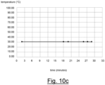
- Figure 10c shows the results of an additional field test. This additional field test was conducted on the same measuring device installed during the previous field test, but few months later. The road section with the renewed pavement had already been opened to traffic, so that the readings of the temperature value provided by the measuring device could be obtained by means of a control device similar to the control device 6 described above.
- the readings were obtained both stationarily (namely, with the control device stationary few meters away from the measuring device), and dynamically (namely, with the control device moving along the road section on board a vehicle at a speed of about 130 km/h).
- Figure 10c shows a graph of the readings of the detected temperature value during the observation period. A substantially constant value of 30°C was repeatedly read, confirming that the measuring device was still properly operating over time, while the pavement is in operating conditions.
Landscapes
- Engineering & Computer Science (AREA)
- Architecture (AREA)
- Civil Engineering (AREA)
- Structural Engineering (AREA)
- Physics & Mathematics (AREA)
- General Physics & Mathematics (AREA)
- General Engineering & Computer Science (AREA)
- Arrangements For Transmission Of Measured Signals (AREA)
- Traffic Control Systems (AREA)
Applications Claiming Priority (1)
| Application Number | Priority Date | Filing Date | Title |
|---|---|---|---|
| IT102023000015381A IT202300015381A1 (it) | 2023-07-21 | 2023-07-21 | Dispositivo e sistema per misurare un parametro fisico relativo alla pavimentazione di un tratto di un’infrastruttura viaria |
Publications (1)
| Publication Number | Publication Date |
|---|---|
| EP4495562A1 true EP4495562A1 (fr) | 2025-01-22 |
Family
ID=88290529
Family Applications (1)
| Application Number | Title | Priority Date | Filing Date |
|---|---|---|---|
| EP24186754.8A Pending EP4495562A1 (fr) | 2023-07-21 | 2024-07-05 | Dispositif et système de mesure d'un paramètre physique relatif à la chaussée d'une section d'infrastructure routière |
Country Status (4)
| Country | Link |
|---|---|
| EP (1) | EP4495562A1 (fr) |
| CL (1) | CL2024002177A1 (fr) |
| IT (1) | IT202300015381A1 (fr) |
| MX (1) | MX2024008802A (fr) |
Citations (5)
| Publication number | Priority date | Publication date | Assignee | Title |
|---|---|---|---|---|
| US20020154029A1 (en) * | 1999-02-26 | 2002-10-24 | Sri International | Sensor devices for structural health monitoring |
| US20080049700A1 (en) * | 2006-08-25 | 2008-02-28 | Shah Rahul C | Reduced power network association in a wireless sensor network |
| WO2013082109A1 (fr) | 2011-11-30 | 2013-06-06 | Caterpillar Paving Products Inc. | Système de pavage utilisant des dispositifs de mesure incorporés |
| CN105528884A (zh) * | 2015-12-27 | 2016-04-27 | 哈尔滨理工大学 | 基于低功耗蓝牙的地温测试系统及地温测试方法 |
| US20220034724A1 (en) * | 2019-04-15 | 2022-02-03 | Concrete Data Sensors Pty Ltd. | Concrete sensor device and system |
-
2023
- 2023-07-21 IT IT102023000015381A patent/IT202300015381A1/it unknown
-
2024
- 2024-07-05 EP EP24186754.8A patent/EP4495562A1/fr active Pending
- 2024-07-15 MX MX2024008802A patent/MX2024008802A/es unknown
- 2024-07-18 CL CL2024002177A patent/CL2024002177A1/es unknown
Patent Citations (5)
| Publication number | Priority date | Publication date | Assignee | Title |
|---|---|---|---|---|
| US20020154029A1 (en) * | 1999-02-26 | 2002-10-24 | Sri International | Sensor devices for structural health monitoring |
| US20080049700A1 (en) * | 2006-08-25 | 2008-02-28 | Shah Rahul C | Reduced power network association in a wireless sensor network |
| WO2013082109A1 (fr) | 2011-11-30 | 2013-06-06 | Caterpillar Paving Products Inc. | Système de pavage utilisant des dispositifs de mesure incorporés |
| CN105528884A (zh) * | 2015-12-27 | 2016-04-27 | 哈尔滨理工大学 | 基于低功耗蓝牙的地温测试系统及地温测试方法 |
| US20220034724A1 (en) * | 2019-04-15 | 2022-02-03 | Concrete Data Sensors Pty Ltd. | Concrete sensor device and system |
Non-Patent Citations (1)
| Title |
|---|
| S. M. NASIMIFAR ET AL.: "Temperature adjustment of Surface Curvature Index from Traffic Speed Deflectometer measurements", INTERNATIONAL JOURNAL OF PAVEMENT ENGINEERING, vol. 21, no. 11, November 2018 (2018-11-01), pages 1 - 11 |
Also Published As
| Publication number | Publication date |
|---|---|
| MX2024008802A (es) | 2025-02-10 |
| IT202300015381A1 (it) | 2025-01-21 |
| CL2024002177A1 (es) | 2024-11-15 |
Similar Documents
| Publication | Publication Date | Title |
|---|---|---|
| Bajwa et al. | In-pavement wireless weigh-in-motion | |
| KR101710666B1 (ko) | 무선 네트워크 기반 복합 사면 감시 장치 및 방법 | |
| US6796187B2 (en) | Wireless multi-functional sensor platform, system containing same and method for its use | |
| KR100869571B1 (ko) | 강우에 의한 사면 붕괴 감시 시스템 및 감시 방법 | |
| US20120004848A1 (en) | Device and methods for use of a dynamic cone penetrometer for evaluating soil compaction | |
| KR101008251B1 (ko) | 무선 센서 네트워크를 이용한 토목구조물의 원격 자동 계측 방법 및 그 시스템 | |
| RU2521778C1 (ru) | Устройство дистанционного контроля состояния провода, грозозащитного троса или кабеля воздушной линии электропередачи | |
| JP5279460B2 (ja) | 道路施設の保守管理支援方法及びそのシステム | |
| WO2012038955A1 (fr) | Système et procédé de pesage en mouvement du type piézoélectrique pour véhicules en mouvement | |
| CN107490998A (zh) | 传感器装置、传感器系统及测定方法 | |
| KR20100053830A (ko) | 산사태 및 낙석 조기경보 시스템 및 방법 | |
| WO2010122284A1 (fr) | Dispositif de comptage de trafic | |
| KR20090046392A (ko) | 지자기 센서를 이용한 매립형 교통정보 측정 장치 | |
| EP4495562A1 (fr) | Dispositif et système de mesure d'un paramètre physique relatif à la chaussée d'une section d'infrastructure routière | |
| KR101928781B1 (ko) | 지중케이블 상태 감시 시스템, 장치 및 방법 | |
| Kane et al. | Instrumentation practice for slope monitoring | |
| KR101288608B1 (ko) | 압전소자를 포함한 전력발생기를 이용한 철도차량의 다기능 검지장치 | |
| KR102175141B1 (ko) | 지반앵커노드의 센서데이터를 활용한 재난 방지용 경사면 변위 측정시스템 | |
| CN102369561B (zh) | 监控交通的装置和方法 | |
| KR102030519B1 (ko) | 균열감지장치 | |
| Ceylan et al. | Development of a wireless MEMS multifunction sensor system and field demonstration of embedded sensors for monitoring concrete pavements: volume I | |
| CN115480293B (zh) | 基于mems传感技术的落石监测预警系统和方法 | |
| JPH11295111A (ja) | 土砂異常検出システム | |
| KR100658494B1 (ko) | 사면 계측 장치, 계측 시스템 및 계측 방법 | |
| CN212254166U (zh) | 基于光纤光栅的立交桥的安全监测装置 |
Legal Events
| Date | Code | Title | Description |
|---|---|---|---|
| PUAI | Public reference made under article 153(3) epc to a published international application that has entered the european phase |
Free format text: ORIGINAL CODE: 0009012 |
|
| STAA | Information on the status of an ep patent application or granted ep patent |
Free format text: STATUS: THE APPLICATION HAS BEEN PUBLISHED |
|
| AK | Designated contracting states |
Kind code of ref document: A1 Designated state(s): AL AT BE BG CH CY CZ DE DK EE ES FI FR GB GR HR HU IE IS IT LI LT LU LV MC ME MK MT NL NO PL PT RO RS SE SI SK SM TR |
|
| STAA | Information on the status of an ep patent application or granted ep patent |
Free format text: STATUS: REQUEST FOR EXAMINATION WAS MADE |
|
| 17P | Request for examination filed |
Effective date: 20250707 |