EP4495565A1 - Dispositif de couplage mécanique à capteur - Google Patents
Dispositif de couplage mécanique à capteur Download PDFInfo
- Publication number
- EP4495565A1 EP4495565A1 EP24189672.9A EP24189672A EP4495565A1 EP 4495565 A1 EP4495565 A1 EP 4495565A1 EP 24189672 A EP24189672 A EP 24189672A EP 4495565 A1 EP4495565 A1 EP 4495565A1
- Authority
- EP
- European Patent Office
- Prior art keywords
- screw
- mechanical coupling
- microelectromechanical sensor
- coupling device
- detection structure
- Prior art date
- Legal status (The legal status is an assumption and is not a legal conclusion. Google has not performed a legal analysis and makes no representation as to the accuracy of the status listed.)
- Pending
Links
Images



Classifications
-
- G—PHYSICS
- G01—MEASURING; TESTING
- G01L—MEASURING FORCE, STRESS, TORQUE, WORK, MECHANICAL POWER, MECHANICAL EFFICIENCY, OR FLUID PRESSURE
- G01L5/00—Apparatus for, or methods of, measuring force, work, mechanical power, or torque, specially adapted for specific purposes
- G01L5/24—Apparatus for, or methods of, measuring force, work, mechanical power, or torque, specially adapted for specific purposes for determining value of torque or twisting moment for tightening a nut or other member which is similarly stressed
-
- F—MECHANICAL ENGINEERING; LIGHTING; HEATING; WEAPONS; BLASTING
- F16—ENGINEERING ELEMENTS AND UNITS; GENERAL MEASURES FOR PRODUCING AND MAINTAINING EFFECTIVE FUNCTIONING OF MACHINES OR INSTALLATIONS; THERMAL INSULATION IN GENERAL
- F16B—DEVICES FOR FASTENING OR SECURING CONSTRUCTIONAL ELEMENTS OR MACHINE PARTS TOGETHER, e.g. NAILS, BOLTS, CIRCLIPS, CLAMPS, CLIPS OR WEDGES; JOINTS OR JOINTING
- F16B31/00—Screwed connections specially modified in view of tensile load; Break-bolts
- F16B31/02—Screwed connections specially modified in view of tensile load; Break-bolts for indicating the attainment of a particular tensile load or limiting tensile load
Definitions
- the present solution relates to a mechanical coupling device, in particular of the screw or bolt type, sensorized by means of a microelectromechanical sensor, of a MEMS (Micro Electro Mechanical Sensor) type, having a high resolution for measuring surface micro-deformations.
- a mechanical coupling device in particular of the screw or bolt type, sensorized by means of a microelectromechanical sensor, of a MEMS (Micro Electro Mechanical Sensor) type, having a high resolution for measuring surface micro-deformations.
- MEMS Micro Electro Mechanical Sensor
- strain gauges in the stem of a screw, or on the faces of the head of the screw or of the locking nut, in order to monitor the load strength thereof, namely the preload or the load force to which the screw is subjected following its tightening.
- cylindrical strain gauges with axial extension can be utilized, inserted in a hole, made on the upper part of the screw, for example having a hexagonal head, and partly continuing in the stem of the same screw.
- strain gauges allow measuring and monitoring the load strength of the screw, their application involves an invasive intervention on the screw (which can alter also in a significant manner the structural characteristics of the same screw) and it is possible only for screws and nuts having sufficiently large dimensions, which can house the aforementioned strain gauges; furthermore, the cost of such solutions is generally high.
- Such document discloses an intelligent bolt which comprises a screw having a main body wherein a central hole is made inside which a pull rod is inserted.
- An elastomer, to which strain gauges are coupled, is mounted on the head of the screw, so as to be in contact with an end of the pull rod. The preload of the bolt and the flexure state of the screw can be detected with precision thanks to the deformation of the pull rod and the corresponding deformation of the elastomer detectable by the strain gauges.
- DE 10 2020 116618 A1 discloses a further known solution, which envisages the use of one or preferably more deformation detection sensors (strain gauges) applied on the side surfaces (or faces) of a nut for detecting a deformation and a preload force of the same nut.
- deformation detection sensors strain gauges
- Such solution further provides for an electronic circuit integrated in a ring-shaped board (PCB) installed in a through opening made in the nut; such electronic circuit defines a radiofrequency unit (RFID) coupled, by means of electrical connection tracks, to the deformation sensors and which can be coupled in communication to an external RFID reader.
- RFID radiofrequency unit
- Another known solution provides for utilizing washers sensorized by means of piezoelectric sensors, having a housing with suitable dimensions for accommodating the screw to be monitored.
- a further method for knowing in an indirect manner the load strength of the screw is to utilize a tightening wrench with dynamometer, for measuring the tightening torque.
- a tightening wrench with dynamometer for measuring the tightening torque.
- Such measurement is anyway imprecise as the relation between the tightening torque and the screw load strength is influenced by the frictions between screw head and resting base and between screw threads and nut screws which are highly variable as a function of the surface coatings, the finishing and the presence of greases or lubricants.
- the aim of the present solution is in general to provide an answer to the aforementioned need.
- an aspect of the present solution provides for sensorizing a mechanical coupling device, in the example a screw 2, in particular a screw having a hexagonal flat head, by means of the application of a microelectromechanical sensor 1.
- the microelectromechanical sensor 1 is externally coupled to the screw 2 (completely outside a corresponding external surface portion), at a head portion 2a thereof, in particular being coupled on a front face of such head portion 2a opposite a rear face coupled to a stem portion 2b of the same screw 2.
- the microelectromechanical sensor 1 is bonded to the aforementioned front face of the head portion 2a of the screw 2.
- such coupling of the microelectromechanical sensor 1 to the screw 2 does not involve any invasive impact or structural modification to the same screw 2 and furthermore does not oblige to utilize or purchase dedicated components or tools.
- the microelectromechanical sensor 1 is a MEMS deformation sensor having a high sensibility (also by various orders of magnitude higher than traditional solutions for measuring deformations, for example than the above-mentioned strain gauges) and is configured to detect deformations at the head portion 2a of the screw 2 and provide an electrical detection signal as a function of such deformations, which can be correlated to one or more physical quantities which generated such deformations and are associated with the operation and in particular with the operating conditions of the screw 2.
- the microelectromechanical sensor 1 is capable of providing a detection and a monitoring of physical quantities related to the operating performances of the screw 2.
- physical quantities comprise a tightening torque and a load strength, or load force, of the screw 2.
- the aforementioned MEMS deformation sensor thus provides an indication of the actual operating conditions of the screw 2 to which it is coupled (in terms of physical quantities associated with its operation).
- the microelectromechanical sensor 1 considering the strain deformation ⁇ in a dimensionless manner, such as ⁇ L/L (where ⁇ L is the variation of a dimensional parameter, for example length L, following the deformation), the microelectromechanical sensor 1 according to the present solution is capable of detecting deformations in the range 10 -5 - 10 -10 (namely nanodeformations, n- ⁇ ), unlike traditional strain gauges which are not capable of going beyond 10 -6 ; this means that with the microelectromechanical sensor 1 it is possible to obtain a sensibility even 10000 times greater in detecting the small deformations.
- the microelectromechanical sensor 1 is configured to allow obtaining, as a function of the processing of the deformations detected at the head portion 2a of the screw 2, an electrical output signal, indicated in the following by S out , which can be correlated, after a suitable preliminary correlation operation, to any of the aforementioned physical quantities (for example, tightening torque and load strength).
- the more suitable positioning of the microelectromechanical sensor 1 on the head portion 2a of the screw 2 can be determined for example by means of preliminary finite element analyses (FEM - Finite Element Method) aimed at identifying a better position in terms of ratio between detected signal and maximum range of the sensor (furthermore a position in which the material of the aforementioned screw 2 has a certainly elastic behaviour).
- FEM - Finite Element Method preliminary finite element analyses
- the same analyses can further allow correlating the detected deformation to the value of the quantity to be detected (for example the tightening torque or the load strength).
- such correlation can be implemented by means of the aid of on-bench deformation measurements, by utilizing suitable measurement instruments (for example of the tightening torque in relation to the screw load strength).
- the screw 2 provided of the microelectromechanical sensor 1 consequently is sensorized or "intelligent", as it is capable of directly providing at the output, for example to an external monitoring system, information related to its operation and to its operating conditions, in terms of the corresponding significant physical quantities, such as the tightening torque and the load strength or load force.
- the microelectromechanical sensor 1 is capable of measuring with a high sensibility the surface deformations which are generated on the head portion 2a of the screw 2 following the application of a twisting torque in the tightening step; and furthermore, in a joint or combined manner, the deformations related to the load strength on the stem portion 2b of the same screw 2 once the application of the tightening torque is interrupted and only the load force remains, which is the objective of the threaded coupling.
- the microelectromechanical sensor 1 operates in the field of elastic deformation of the material of the screws (for example, with maximum deformation values up to 500 microstrain, for example around 250 microstrain) and since such elastic behaviour of the screws is guaranteed by design (for preventing permanent deformations of the threaded member, by design suitable safety coefficients are provided), the same microelectromechanical sensor 1 is suited for all the applications and on screws having different measures, load strength values and tightening torque values.
- the calibration of the microelectromechanical sensor 1 (correlation between read deformation and tightening torque/load strength applied to the screw 2) can be preliminarily performed by means of FEM analysis of the screw 2 subjected to the load, or with a real measurement of the tightening torque or of the load strength with a dedicated test bench.
- Figure 2 shows the trend of an output signal S out generated based on the detection signal provided by the microelectromechanical sensor 1, associated with the physical quantities indicative of the operation and of the operating conditions of the screw 2.
- the output signal S out being a function of the deformation perceived on the head portion 2a of the screw 2, is proportional to the torque applied in the tightening step.
- the aforementioned torque applied to the head portion 2a of the screw 2 is zeroed, so that the share of deformation due to the twisting torque disappears and the residual deformation signal is proportional only to the load strength on the stem portion 2b of the screw 2, which is discharged on the head portion 2a and is detected by the microelectromechanical sensor 1.
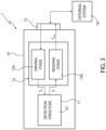
- the microelectromechanical sensor 1 may comprise a detection structure 10, of a MEMS type, integrated in a die 11 of semiconductor material, in particular silicon, configured to be coupled to the aforementioned head portion 2a of the screw 2 for detecting the surface deformations.
- the microelectromechanical sensor 1 further comprises, in an integrated manner, an electronic circuit 12, operatively coupled to the detection structure 10 and implementing a driving stage 12a configured to provide driving signals S d for the detection structure 10 and a reading stage 12b configured to receive and process detection signals S r provided by the detection structure 10 for generating the output signal S out associated with the desired physical quantity indicative of the operation and of the operating conditions of the screw 2.
- Such electronic circuit 12 can be made with discrete components on a flexible printed circuit (PCB flex - Printed Circuit Board flex) or in an integrated manner by utilizing ASIC (ASIC - Application Specific Integrated Circuit) semiconductors.
- PCB flex - Printed Circuit Board flex PCB flex - Printed Circuit Board flex
- ASIC Application Specific Integrated Circuit
- the reading stage 12b is configured for: processing the detection signal S r provided by the detection structure 10 as a function of the detected deformations; and generating the output signal S out , which can directly provide a measurement correlated to the physical quantity of interest (indicative of the operation and of the operating conditions of the screw 2).
- the reading stage 12b can internally comprise a memory for storing preliminary characterization information associated with the mechanical coupling device (screw 2), for implementing the aforementioned correlation between the output signal S out and the quantity to be measured.
- the microelectromechanical sensor 1 can also comprise more than one detection structure 10 (of a MEMS type) for measuring microdeformations on more surface directions.
- the microelectromechanical sensor 1 comprises a package 14 which encloses the detection structure 10 and, in the example, the electronic circuit 12, for example made of a thermoplastic co-moulded material.
- the aforementioned package 14 advantageously has small dimensions, for example of approximately 20x20 mm (but which can also reach 5x5 mm) and is designed to be coupled entirely externally to the screw, in particular to the aforementioned head portion 2a of the same screw 2.
- an electrical connector 15 can be externally associated with the package 14, configured to provide an electric interface of the microelectromechanical sensor 1 towards the external environment, for example towards an external electronic system 16 configured to receive the aforementioned output signal S out and to perform further processing operations as a function of the same output signal S out .
- the external electronic system 16 can further provide a power supply to the microelectromechanical sensor 1 through the aforementioned electrical connector 15.
- such electrical connector 15 can be an industrial connector with degree of protection IP68 (or similar) of a multipolar type (generally a 4-pin type).
- connection between the microelectromechanical sensor 1 and the external electronic system 16 can be implemented in a wireless manner, with wireless connection technologies, for example with Bluetooth protocol, preferably with reduced energy consumption (BT Low Energy).
- the detection structure 10 and the electronic circuit 12 can be powered by battery, or, advantageously in the absence of a battery, with an induction power supply system (by the external electronic system 16, which can approach the microelectromechanical sensor 1 during measurement).
- a wireless connection solution can advantageously allow integrating in a watertight manner on the head portion 2a of the screw 2 the microelectromechanical sensor 1 (inclusive of the detection structure 10 and of the electronic circuit 12) .
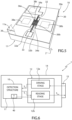
- the microelectromechanical sensor 1 comprises a substrate or support 20, which has a top face 20a and a bottom face 20b, the latter configured to be coupled, at least partly in contact, to the head portion 2a of the screw 2.
- the die 11 of the detection structure 10 is coupled by means of a flip-chip coupling to the bottom face 20b of the support 20, at a first distal portion 20' thereof.
- a front face (indicated in the following by 11a) of the die 11, at which constitutive elements of the detection structure 10 and corresponding electrical connection pads are formed, is mechanically and electrically coupled (by means of bonding) to the aforementioned bottom face 20b of the support 20.
- a rear face 11b (or base) of the aforementioned die 11, vertically opposite the aforementioned front face 11a, is instead designed to be coupled, for example by means of bonding or other fastening techniques (for example welding), to the head portion 2a of the screw 2.
- Such rear face 11b can conveniently be accessible from the outside of the package 14 of the microelectromechanical sensor 1, for example being arranged flush with an external surface of the same package 14.
- At least part of the aforementioned support 20, in particular the aforementioned first distal portion 20' is made of a flexible material, for example Kapton, so as to facilitate the coupling to the aforementioned casing and furthermore so as to ease the detection of the deformations by the detection structure 10.
- a flexible material for example Kapton
- the electronic circuit 12 of the microelectromechanical sensor 1 is coupled to the upper face 20a of the support 20, at a second distal portion 20" thereof, longitudinally opposite the aforementioned first distal portion 20'; in particular, Figure 4B illustrates by way of mere example electronic components 22 of the aforementioned electronic circuit 12 (here made in a discrete embodiment), electrically welded to the aforementioned top face 20a of the support 20.
- the second distal portion 20" of the support 20 is in this case a printed circuit board portion (advantageously, made of flexible material, as well).
- suitable conductive tracks and paths of electrical connection are made in the support 20, which thus acts as an electrical coupling interface between the detection structure 10 and the associated electronic circuit 12.
- pins 15' of the electrical connector 15 are coupled to pads carried by the top face 20a of the support 20, so as to allow, as previously discussed, the provision of the power supply to the microelectromechanical sensor 1 and furthermore the provision of the output signal S out to the outside of said microelectromechanical sensor 1.
- the detection structure 10 of the microelectromechanical sensor 1 may define a flexural MEMS resonator, integrated in the aforementioned die 11 with a wafer level package.
- the detection structure 10 can be manufactured as specifically described in the document L. Belsito et al., "Fabrication of high-resolution strain sensors based on wafer-level vacuum packaged MEMS resonators", Sensors and Actuators A: Physical, Volume 239, 2016, pp. 90-101 .
- the detection structure 10 is in such case made in a substrate 30 of the aforementioned die 11, for example a SOI, Silicon On Insulator, substrate and comprises a resonating element 32, of clamped-clamped type, defined by means of the machining of an active layer 30a of the same substrate 30.
- the resonating element 32 comprises a first and a second arm 32a, 32b, constrained to each other at corresponding longitudinal ends separated along their longitudinal extension by a gap 33.
- Such first and second arms 32a, 32b have greater length along a first axis x of a horizontal plane xy, reduced width (along a second axis y of said horizontal plane xy) and reduced thickness (along a vertical axis z, orthogonal to the horizontal plane xy), so as to be yieldable to a flexure in the same horizontal plane xy.
- first and second arms 32a, 32b are integrally coupled, at a corresponding central portion, to a first and, respectively, a second movable electrode 34a, 34b, which are arranged on the opposite side of the aforementioned gap 33 with respect to the second horizontal axis y.
- the detection structure 10 further comprises a first and a second fixed electrodes 36a, 36b, arranged facing, at a given distance of separation, the first and the second movable electrodes 34a, 34b, respectively, so as to make a respective capacitive coupling.
- a first and a second connection pads 38a, 38b are electrically coupled to the first and to the second fixed electrodes 36a, 36b, respectively, and furthermore a third connection pad 38c is electrically coupled to the aforementioned first and second movable electrodes 34a, 34b.
- the detection structure 10 further comprises a cap 39 (schematically illustrated herein in a partial manner) which hermetically closes at the top the resonating element 32, creating a vacuum condition, so as to facilitate the actuation thereof in resonance condition (without dampening effects due to the presence of air).
- a top surface of such cap 39 further constitutes the aforementioned front face 11a of the die 11.
- the driving signals S d provided by the driving stage 12a of the electronic circuit 10 cause the actuation at the resonance frequency of the resonating element 32, for example with a push-pull oscillation movement of the first and second arms 32a, 32b.
- the deformations perceived by the detection structure 10 cause a modification of the aforementioned resonance frequency associated with the resonating element 32.
- An oscillation voltage of such resonating element 32 can constitute in such case the detection signal S r provided by the detection structure 10 to the reading stage 12b of the electronic circuit 12, indicative of the deformations and based on which the same electronic circuit 12 is capable of providing the output signal S out , correlated to the physical quantities associated with the operation and the operating conditions of the screw 2.
- a further aspect of the present solution can provide for the possibility to compensate, internally the microelectromechanical sensor 1, a total deformation value measured by the same microelectromechanical sensor 1, eliminating a part, or share, which is not related to the quantity to be measured (for example, tightening torque or load strength of the screw 2), but which is due to a thermal deformation of the material following a temperature variation.
- a temperature transducer (T) 40 can be in such case formed directly within the detection structure 10, inside the package 14, for example in the aforementioned die 11, so as to provide an indication of the temperature value during detection.
- the manufacturing of a dummy resonating element could be provided, specifically configured to be insensible to the deformations, but sensible to the temperature, so as to provide a compensation signal S c with which the reading stage 12b can be capable of compensating the detection signal S r provided by the detection structure 10.
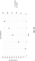
- Figures 7A and 7B show a comparison between tightening torque values (expressed in Nm) and load strength values (expressed in N), respectively, measured by the microelectromechanical sensor 1 (obtained based on the values of the aforementioned output signal S out ) and corresponding values of the same quantities measured by means of an experimental test bench (during the tests, the sensorized screw 2 was placed in the test bench, so as to simultaneously carry out the comparison measurements).
- the microelectromechanical sensor 1 is also suited for a continuous monitoring over time of the load strength of the screw 2, load strength which can change for example due to loosening of the threaded coupling or following the application of loads on the same coupling.
- the microelectromechanical sensor 1 is thus also capable of carrying out a diagnostic of the threaded coupling and a prognostic (estimate of the residual life) also evaluating the fatigue cycles which over time are applied to the threaded connection.
- the microelectromechanical sensor 1 can also provide an indication of the temperature of the screw 2, which could be useful for evaluating the thermal expansions on the coupling, which could cause loosening problems or breakages.
- the microelectromechanical sensor 1 could integrate on board, inside the electronic circuit 12, a processing stage, for example an artificial intelligence (AI) processing stage, with the aim to autonomously perform processing algorithms, for example machine learning algorithms, aimed at evaluating the performances and/or the operating conditions of the screw 2.
- a processing stage for example an artificial intelligence (AI) processing stage
- AI artificial intelligence
- processing algorithms for example machine learning algorithms
- processing algorithms could be aimed at predictive diagnostics and prognostics based on the time evolution of the deformation signal (and/or of the output signal S out ) and thus of the aforementioned physical quantities (it should be noted that such additional processing operations of predictive diagnostics and prognostics with respect to the aforementioned deformation measurements can be available thanks to the high sensibility of the microelectromechanical sensor 1).
- the aforementioned algorithms and the aforementioned predictive diagnostic and prognostic analyses could, alternatively or additionally, be implemented externally the microelectromechanical sensor 1, by the aforementioned external electronic system 16.
- the possible presence of conditioning and processing algorithms of the signals detected inside the microelectromechanical sensor 1 can advantageously provide a monitoring solution directly usable by a final user.
- the microelectromechanical sensor 1 could integrate more than one detection structure 10, in particular more than one resonating element 32, for example in order to allow a measurement of several physical quantities and/or the compensation, for example in temperature, of the output signal S out .
- the electronic circuit 12, operatively coupled to the detection structure 10 could be made externally the microelectromechanical sensor 1, for example in the external electronic system 16, as it is suitably connected, in a wired or wireless manner, to the same detection structure 10.
Landscapes
- Engineering & Computer Science (AREA)
- General Engineering & Computer Science (AREA)
- Mechanical Engineering (AREA)
- Physics & Mathematics (AREA)
- General Physics & Mathematics (AREA)
- Measuring Fluid Pressure (AREA)
Applications Claiming Priority (1)
| Application Number | Priority Date | Filing Date | Title |
|---|---|---|---|
| IT102023000015348A IT202300015348A1 (it) | 2023-07-21 | 2023-07-21 | Dispositivo di accoppiamento meccanico sensorizzato |
Publications (1)
| Publication Number | Publication Date |
|---|---|
| EP4495565A1 true EP4495565A1 (fr) | 2025-01-22 |
Family
ID=88290755
Family Applications (1)
| Application Number | Title | Priority Date | Filing Date |
|---|---|---|---|
| EP24189672.9A Pending EP4495565A1 (fr) | 2023-07-21 | 2024-07-19 | Dispositif de couplage mécanique à capteur |
Country Status (2)
| Country | Link |
|---|---|
| EP (1) | EP4495565A1 (fr) |
| IT (1) | IT202300015348A1 (fr) |
Citations (3)
| Publication number | Priority date | Publication date | Assignee | Title |
|---|---|---|---|---|
| DE102017219196A1 (de) * | 2017-10-26 | 2019-05-02 | Robert Bosch Gmbh | Sensoranordnung und Verfahren zur Ermittlung eines Drehmoments und/oder einer Kraft und Arbeitsgerät |
| CN109738106A (zh) | 2019-01-11 | 2019-05-10 | 重庆大学 | 一种能检测螺栓预紧力及螺杆弯曲状态的无线智能螺栓 |
| DE102020116618A1 (de) | 2020-06-24 | 2021-12-30 | Micro-Sensys Gmbh | Schraubenmutter und Montagevorrichtung |
-
2023
- 2023-07-21 IT IT102023000015348A patent/IT202300015348A1/it unknown
-
2024
- 2024-07-19 EP EP24189672.9A patent/EP4495565A1/fr active Pending
Patent Citations (3)
| Publication number | Priority date | Publication date | Assignee | Title |
|---|---|---|---|---|
| DE102017219196A1 (de) * | 2017-10-26 | 2019-05-02 | Robert Bosch Gmbh | Sensoranordnung und Verfahren zur Ermittlung eines Drehmoments und/oder einer Kraft und Arbeitsgerät |
| CN109738106A (zh) | 2019-01-11 | 2019-05-10 | 重庆大学 | 一种能检测螺栓预紧力及螺杆弯曲状态的无线智能螺栓 |
| DE102020116618A1 (de) | 2020-06-24 | 2021-12-30 | Micro-Sensys Gmbh | Schraubenmutter und Montagevorrichtung |
Non-Patent Citations (1)
| Title |
|---|
| BELSITO ET AL.: "Fabrication of high-resolution strain sensors based on wafer-level vacuum packaged MEMS resonators", SENSORS AND ACTUATORS A: PHYSICAL, vol. 239, 2016, pages 90 - 101, XP029415369, DOI: 10.1016/j.sna.2016.01.006 |
Also Published As
| Publication number | Publication date |
|---|---|
| IT202300015348A1 (it) | 2025-01-21 |
Similar Documents
| Publication | Publication Date | Title |
|---|---|---|
| EP3722765B1 (fr) | Cellule de charge | |
| EP2175147B1 (fr) | Appareil de fixation à indication de charge | |
| KR102629855B1 (ko) | 토크 전달 샤프트에 인가되는 힘 및/또는 토크를 결정하기 위한 측정 장치 및 방법 | |
| JPH04231828A (ja) | 力、ひずみ及び構造物伝送ノイズ変換器複合体 | |
| JP2004535536A (ja) | ピン部材内の曲げを測定するシステム及び方法 | |
| WO2007146724A1 (fr) | Procédé et appareil de test de contrainte de cisaillement de capteurs de contrainte | |
| Elbestawi | Force measurement | |
| EP4495565A1 (fr) | Dispositif de couplage mécanique à capteur | |
| EP3676502B1 (fr) | Dispositif de fixation et procédé de fabrication d'un tel dispositif | |
| JPH0712667A (ja) | 物理量センサおよび物理量センサシステム | |
| CN101275858B (zh) | 用于钢构弹性角检测的微角位移传感器及其测量方法 | |
| EP4279897A2 (fr) | Capteur micro-électromécanique pour surveiller un dispositif de transmission de puissance mécanique et dispositif de transmission de puissance mécanique à capteur correspondant | |
| US7146847B2 (en) | Knock sensor for an internal combustion engine | |
| KR200144765Y1 (ko) | 진동 및 온도 온라인 측정시스템 | |
| US20230398624A1 (en) | Device for measuring the welding force and detecting the electrical welding voltage during a welding process of a resistance welding device | |
| EP1509703A1 (fr) | Element de fixation indiquant une charge | |
| EP4390339B1 (fr) | Cellule de charge et construction de conteneur avec celle-ci | |
| CN201199163Y (zh) | 用于钢构弹性角检测的微角位移传感器 | |
| CN109357651A (zh) | 精密驱动位移测量装置 | |
| Hillinger | Force Measurement with Piezo Electric Sensors in Advanced Packaging | |
| Divay et al. | Highly sensitive force sensor featuring a MEMS-instrumented buckling lamella | |
| SU1566236A1 (ru) | Датчик давлени | |
| CN120084465A (zh) | 多维力传感器 | |
| Elbestawi | 23.2 Hooke’s Law | |
| CN109115136A (zh) | 角微位移传感器 |
Legal Events
| Date | Code | Title | Description |
|---|---|---|---|
| PUAI | Public reference made under article 153(3) epc to a published international application that has entered the european phase |
Free format text: ORIGINAL CODE: 0009012 |
|
| STAA | Information on the status of an ep patent application or granted ep patent |
Free format text: STATUS: THE APPLICATION HAS BEEN PUBLISHED |
|
| AK | Designated contracting states |
Kind code of ref document: A1 Designated state(s): AL AT BE BG CH CY CZ DE DK EE ES FI FR GB GR HR HU IE IS IT LI LT LU LV MC ME MK MT NL NO PL PT RO RS SE SI SK SM TR |
|
| STAA | Information on the status of an ep patent application or granted ep patent |
Free format text: STATUS: REQUEST FOR EXAMINATION WAS MADE |
|
| 17P | Request for examination filed |
Effective date: 20250722 |