EP4495621A1 - Procédés et systèmes d'étalonnage d'un capteur de mouvement - Google Patents
Procédés et systèmes d'étalonnage d'un capteur de mouvement Download PDFInfo
- Publication number
- EP4495621A1 EP4495621A1 EP23186982.7A EP23186982A EP4495621A1 EP 4495621 A1 EP4495621 A1 EP 4495621A1 EP 23186982 A EP23186982 A EP 23186982A EP 4495621 A1 EP4495621 A1 EP 4495621A1
- Authority
- EP
- European Patent Office
- Prior art keywords
- vehicle
- sensor
- motion
- implemented method
- computer implemented
- Prior art date
- Legal status (The legal status is an assumption and is not a legal conclusion. Google has not performed a legal analysis and makes no representation as to the accuracy of the status listed.)
- Pending
Links
Images


Classifications
-
- G—PHYSICS
- G01—MEASURING; TESTING
- G01S—RADIO DIRECTION-FINDING; RADIO NAVIGATION; DETERMINING DISTANCE OR VELOCITY BY USE OF RADIO WAVES; LOCATING OR PRESENCE-DETECTING BY USE OF THE REFLECTION OR RERADIATION OF RADIO WAVES; ANALOGOUS ARRANGEMENTS USING OTHER WAVES
- G01S7/00—Details of systems according to groups G01S13/00, G01S15/00, G01S17/00
- G01S7/02—Details of systems according to groups G01S13/00, G01S15/00, G01S17/00 of systems according to group G01S13/00
- G01S7/40—Means for monitoring or calibrating
- G01S7/4052—Means for monitoring or calibrating by simulation of echoes
- G01S7/4082—Means for monitoring or calibrating by simulation of echoes using externally generated reference signals, e.g. via remote reflector or transponder
- G01S7/4091—Means for monitoring or calibrating by simulation of echoes using externally generated reference signals, e.g. via remote reflector or transponder during normal radar operation
-
- G—PHYSICS
- G01—MEASURING; TESTING
- G01C—MEASURING DISTANCES, LEVELS OR BEARINGS; SURVEYING; NAVIGATION; GYROSCOPIC INSTRUMENTS; PHOTOGRAMMETRY OR VIDEOGRAMMETRY
- G01C25/00—Manufacturing, calibrating, cleaning, or repairing instruments or devices referred to in the other groups of this subclass
-
- G—PHYSICS
- G01—MEASURING; TESTING
- G01C—MEASURING DISTANCES, LEVELS OR BEARINGS; SURVEYING; NAVIGATION; GYROSCOPIC INSTRUMENTS; PHOTOGRAMMETRY OR VIDEOGRAMMETRY
- G01C21/00—Navigation; Navigational instruments not provided for in groups G01C1/00 - G01C19/00
- G01C21/38—Electronic maps specially adapted for navigation; Updating thereof
- G01C21/3804—Creation or updating of map data
- G01C21/3833—Creation or updating of map data characterised by the source of data
- G01C21/3837—Data obtained from a single source
-
- G—PHYSICS
- G01—MEASURING; TESTING
- G01C—MEASURING DISTANCES, LEVELS OR BEARINGS; SURVEYING; NAVIGATION; GYROSCOPIC INSTRUMENTS; PHOTOGRAMMETRY OR VIDEOGRAMMETRY
- G01C22/00—Measuring distance traversed on the ground by vehicles, persons, animals or other moving solid bodies, e.g. using odometers, using pedometers
-
- G—PHYSICS
- G01—MEASURING; TESTING
- G01C—MEASURING DISTANCES, LEVELS OR BEARINGS; SURVEYING; NAVIGATION; GYROSCOPIC INSTRUMENTS; PHOTOGRAMMETRY OR VIDEOGRAMMETRY
- G01C25/00—Manufacturing, calibrating, cleaning, or repairing instruments or devices referred to in the other groups of this subclass
- G01C25/005—Manufacturing, calibrating, cleaning, or repairing instruments or devices referred to in the other groups of this subclass initial alignment, calibration or starting-up of inertial devices
-
- G—PHYSICS
- G01—MEASURING; TESTING
- G01P—MEASURING LINEAR OR ANGULAR SPEED, ACCELERATION, DECELERATION, OR SHOCK; INDICATING PRESENCE, ABSENCE, OR DIRECTION, OF MOVEMENT
- G01P21/00—Testing or calibrating of apparatus or devices covered by the preceding groups
- G01P21/02—Testing or calibrating of apparatus or devices covered by the preceding groups of speedometers
-
- G—PHYSICS
- G01—MEASURING; TESTING
- G01S—RADIO DIRECTION-FINDING; RADIO NAVIGATION; DETERMINING DISTANCE OR VELOCITY BY USE OF RADIO WAVES; LOCATING OR PRESENCE-DETECTING BY USE OF THE REFLECTION OR RERADIATION OF RADIO WAVES; ANALOGOUS ARRANGEMENTS USING OTHER WAVES
- G01S13/00—Systems using the reflection or reradiation of radio waves, e.g. radar systems; Analogous systems using reflection or reradiation of waves whose nature or wavelength is irrelevant or unspecified
- G01S13/88—Radar or analogous systems specially adapted for specific applications
- G01S13/89—Radar or analogous systems specially adapted for specific applications for mapping or imaging
-
- G—PHYSICS
- G01—MEASURING; TESTING
- G01S—RADIO DIRECTION-FINDING; RADIO NAVIGATION; DETERMINING DISTANCE OR VELOCITY BY USE OF RADIO WAVES; LOCATING OR PRESENCE-DETECTING BY USE OF THE REFLECTION OR RERADIATION OF RADIO WAVES; ANALOGOUS ARRANGEMENTS USING OTHER WAVES
- G01S13/00—Systems using the reflection or reradiation of radio waves, e.g. radar systems; Analogous systems using reflection or reradiation of waves whose nature or wavelength is irrelevant or unspecified
- G01S13/88—Radar or analogous systems specially adapted for specific applications
- G01S13/93—Radar or analogous systems specially adapted for specific applications for anti-collision purposes
- G01S13/931—Radar or analogous systems specially adapted for specific applications for anti-collision purposes of land vehicles
-
- G—PHYSICS
- G01—MEASURING; TESTING
- G01S—RADIO DIRECTION-FINDING; RADIO NAVIGATION; DETERMINING DISTANCE OR VELOCITY BY USE OF RADIO WAVES; LOCATING OR PRESENCE-DETECTING BY USE OF THE REFLECTION OR RERADIATION OF RADIO WAVES; ANALOGOUS ARRANGEMENTS USING OTHER WAVES
- G01S17/00—Systems using the reflection or reradiation of electromagnetic waves other than radio waves, e.g. lidar systems
- G01S17/88—Lidar systems specially adapted for specific applications
- G01S17/89—Lidar systems specially adapted for specific applications for mapping or imaging
-
- G—PHYSICS
- G01—MEASURING; TESTING
- G01S—RADIO DIRECTION-FINDING; RADIO NAVIGATION; DETERMINING DISTANCE OR VELOCITY BY USE OF RADIO WAVES; LOCATING OR PRESENCE-DETECTING BY USE OF THE REFLECTION OR RERADIATION OF RADIO WAVES; ANALOGOUS ARRANGEMENTS USING OTHER WAVES
- G01S17/00—Systems using the reflection or reradiation of electromagnetic waves other than radio waves, e.g. lidar systems
- G01S17/88—Lidar systems specially adapted for specific applications
- G01S17/93—Lidar systems specially adapted for specific applications for anti-collision purposes
- G01S17/931—Lidar systems specially adapted for specific applications for anti-collision purposes of land vehicles
-
- G—PHYSICS
- G01—MEASURING; TESTING
- G01S—RADIO DIRECTION-FINDING; RADIO NAVIGATION; DETERMINING DISTANCE OR VELOCITY BY USE OF RADIO WAVES; LOCATING OR PRESENCE-DETECTING BY USE OF THE REFLECTION OR RERADIATION OF RADIO WAVES; ANALOGOUS ARRANGEMENTS USING OTHER WAVES
- G01S7/00—Details of systems according to groups G01S13/00, G01S15/00, G01S17/00
- G01S7/48—Details of systems according to groups G01S13/00, G01S15/00, G01S17/00 of systems according to group G01S17/00
- G01S7/4808—Evaluating distance, position or velocity data
Definitions
- the present disclosure relates to methods and systems for calibrating a motion sensor arranged at a vehicle and configured to output a raw motion measurement value indicative of a current motion condition of the vehicle.
- Information on the ego motion of a vehicle may be important in various aspects of driving, in particular for advanced driver assistance systems (ADAS) and autonomous driving applications.
- Sensors for gathering ego motion information may need a calibration to compensate for manufacturing tolerances and dependencies of the sensor output on environmental conditions such as the ambient temperature or the tire pressure.
- the use of incorrect ego motion information may be detrimental to various driving applications.
- the present disclosure provides a computer implemented method, a computer system, a non-transitory computer readable medium and a vehicle according to the independent claims. Embodiments are given in the dependent claims, the description and the drawings.
- the present disclosure is directed at a computer implemented method for calibrating a motion sensor arranged at a vehicle and configured to output a raw motion measurement value indicative of a current motion condition of the vehicle, the method comprising the following steps: computing processed motion measurement values by modifying the outputted raw motion measurement value based on a set of different calibration parameters; monitoring the vicinity of the vehicle by means of at least one environment perception sensor; determining a set of occupancy maps by means of mapping data acquired by the environment perception sensor in accordance with a motion model for the vehicle, wherein each of the processed motion measurement values is used to establish the motion model for one of the occupancy maps; and selecting, based on a comparison of the determined occupancy maps, one of the different calibration parameters for modifying subsequently outputted raw motion measurement values.
- the environment perception sensor may be used to calibrate the motion sensor.
- the motion sensor may be calibrated based on the quality of an occupancy map that has been determined with the use of data provided by the motion sensor. It may be assumed that the calibration is good if the occupancy map has a high quality, i. e. shows clear and distinct objects, and the calibration is bad if the occupancy map has a low quality, i. e. rather shows smeared or blurred objects.
- the disclosed calibration process may be carried out onboard and online, i. e. while the motion sensor is operating. It is not necessary to move the vehicle to a test stand.
- An occupancy map also referred to as an occupancy grid or an occupancy map grid, is a map of cells containing information of the cell being occupied by some kind of object.
- the cells may have a fixed width, length and height.
- Occupancy maps are widely used in advanced driver assistance systems and autonomous driving applications, because an occupancy map can be interpreted as a map of obstacles around the vehicle.
- Each occupied cell may represent a non-drivable area.
- An inverted occupancy map can be interpreted as a free space map showing the drivable regions.
- the environment perception sensor may provide reflections from objects in the form of point clouds.
- the term "mapping" may refer to the process of evaluating the correspondence between successively acquired point clouds.
- the motion model may include a constant linear motion with a velocity determined by the motion sensor.
- the motion model may further include a curve component based on a yaw rate provided by a gyroscope arranged at the vehicle. Dependent on the application, a more complex motion model may be provided.
- the method may comprise determining a sharpness value for each of the determined occupancy maps and selecting the calibration parameter based on a comparison of the determined sharpness values.
- the sharpness value may be an indicator for the quality of the occupancy map. I. e. the quality of the mapping process and thus the accuracy of the motion measurement value may be assessed by the sharpness value.
- the quality of the occupancy map may be used to optimize the calibration process.
- an extremal value of the sharpness values may be determined and the calibration parameter used for determining the occupancy map associated with the extremal value may be selected.
- the occupancy map having the highest or lowest sharpness value may be determined and the calibration parameter on which the motion model of this occupancy map is based may be selected.
- the sharpness value may have a positive or a negative correlation with the image sharpness of the occupancy map.
- Such a sharpness metric punishes probability values close to the extremes 0 and 1 less than values close to 0.5. This accounts for the circumstance that a high-quality occupancy map has many extremes, i. e. an accumulation of occupancy probabilities at positions where there is an object and no probability at positions where there is no object, and that a low-quality occupancy map rather has a distributed occupancy probability, i. e. a "smeared" appearance.
- the vicinity of the vehicle may be monitored while the vehicle is moving.
- the present disclosure is also directed at a computer program for instructing a computer to perform several or all steps or aspects of the computer implemented method described herein.
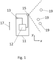
- an occupancy map of the vicinity of the host vehicle 11 may be determined by accumulating readings from the environment perception sensor 15 and transforming the accumulated sensor readings to probabilities over time.
- the occupancy map may include a two-dimensional or three-dimensional grid of cells, wherein an occupancy probability or a free space probability is assigned to each of the cells, as is known in the art.
- the occupancy probability may be updated after each data acquisition process, i. e. after each frame or scan of the environment perception sensor 15.
- the occupancy map shows obstacles in form of stationary objects 19 and thus also shows the drivable space, i. e. the space which is free from obstacles.
- the calibration parameters f and b may be estimated.
- the point clouds acquired by the environment perception sensor 15 are collected and stored in a storage of the computer system 12 for a given number of timestamps or time frames, for example for 10 time frames.
- the point clouds are mapped via an occupancy grid mapping (OGM) process with the free parameters f and b to generate an occupancy map P x y f b , wherein x and y are two-dimensional spatial coordinates as shown in Fig. 1 .
- OGM occupancy grid mapping
- a set of different calibration parameters f, b based on predefined value ranges may be determined.
- the resulting set of calibration parameters includes a plurality of pairs f,b.
- Such a sharpness metric punishes probability values close to the extremes 0 and 1 less than values close to 0.5. This accounts for the circumstance that a high-quality occupancy map has many extremes, i. e. an accumulation of occupancy probabilities at positions where there is an object and no probability at positions where there is no object, and that a low-quality occupancy map rather has a distributed occupancy probability, i. e. a "smeared" appearance.
- Fig. 2 exemplarily shows the sharpness value S ( f,b ) (vertical axis) in dependence of the scaling factor f (horizontal axis). Individually computed values are depicted as points 23. Further, a fitted curve 24 is shown. The minimum 25 of the sharpness values S ( f,b ) , which may be the lowest point 23 or the minimum of the fitted curve 24, defines the optimal value for f , which may be referred to as f opt . An analogous process is carried out to find the optimal value for b , which may be referred to as b opt . By means of a two-dimensional minimum search, both optimum values f opt , b opt may be found in a common process.
- the optimal values f opt and b opt may be selected as calibration parameters for modifying subsequently outputted raw velocity values v .
- f opt and b opt may be determined as current calibration parameters and may be stored in a memory of the computer system 12.
- the estimated parameters may be used by any application module which relies on an ego motion information from the motion sensor 13 and may be re-estimated whenever necessary.
- Fig. 3 shows a flow diagram 400 illustrating a method for calibrating the motion sensor 13 shown in Fig. 1 .
- the calibration method illustrated in Fig. 3 may be carried out on a regular temporal basis, upon receiving an error signal and/or after a repair process has been carried out.
- the method may further include determining a sharpness value for each of the determined occupancy maps and selecting the calibration parameter based on a comparison of the determined sharpness values.
- the method may further include determining an extremal value of the sharpness values and selecting the calibration parameter used for determining the occupancy map associated with the extremal value.
- the method may further include monitoring the vicinity of the vehicle while the vehicle is moving.
- the motion sensor may be an odometry sensor.
- the raw motion measurement value may represent a vehicle velocity
- the environment perception sensor may be a radar sensor, a lidar sensor or a camera.
- the set of different calibration parameters may comprise a plurality of different scaling factors and the method may further include computing the processed motion measurement values by multiplying the raw motion measurement value with the different scaling factors.
- the set of different calibration parameters may comprise a plurality of different bias values and the method may further include computing the processed motion measurement values by adding the different bias values to the raw motion measurement value.
- the different calibration parameters may be spread over a range of values extending in positive direction and in negative direction from an expected value.
- the method may further include collecting data acquired by the environment perception sensor for a predetermined number of time intervals and determining each of the occupancy maps by overlaying the collected data in a spatial representation of the vicinity of the vehicle.
- Each of the steps 402, 404, 406, 408, 410 and the further steps described above may be performed by computer hardware components.
- Fig. 4 shows a computer system 500 with a plurality of computer hardware components configured to carry out steps of a computer implemented method for calibrating a motion sensor according to various embodiments.
- the computer system 500 may include a processor 502, a memory 504, and a non-transitory data storage 506.
- a sensor system 508 may be may be provided as part of the computer system 500 (like illustrated in Fig. 5), or may be provided external to the computer system 500.
- the sensor system 508 may include a motion sensor 13 and an environment perception sensor 15 as shown in Fig. 1 .
- the processor 502 may carry out instructions provided in the memory 504.
- the non-transitory data storage 506 may store a computer program, including the instructions that may be transferred to the memory 504 and then executed by the processor 502.
- the sensor system 508 may be used for capturing the vehicle velocity and for perceiving objects in the vicinity of the vehicle.
- the processor 502, the memory 504, and the non-transitory data storage 506 may be coupled with each other, e.g. via an electrical connection 510, such as e.g. a cable or a computer bus or via any other suitable electrical connection to exchange electrical signals.
- the sensor system 508 may be coupled to the computer system 500, for example via an external interface, or may be provided as parts of the computer system (in other words: internal to the computer system, for example coupled via the electrical connection 510).
- Coupled or “connection” are intended to include a direct “coupling” (for example via a physical link) or direct “connection” as well as an indirect “coupling” or indirect “connection” (for example via a logical link), respectively.
Landscapes
- Engineering & Computer Science (AREA)
- Remote Sensing (AREA)
- Radar, Positioning & Navigation (AREA)
- Physics & Mathematics (AREA)
- General Physics & Mathematics (AREA)
- Computer Networks & Wireless Communication (AREA)
- Manufacturing & Machinery (AREA)
- Electromagnetism (AREA)
- Automation & Control Theory (AREA)
- Traffic Control Systems (AREA)
Priority Applications (3)
| Application Number | Priority Date | Filing Date | Title |
|---|---|---|---|
| EP23186982.7A EP4495621A1 (fr) | 2023-07-21 | 2023-07-21 | Procédés et systèmes d'étalonnage d'un capteur de mouvement |
| US18/758,889 US20250027790A1 (en) | 2023-07-21 | 2024-06-28 | Methods And Systems For Calibrating A Motion Sensor |
| CN202410972252.4A CN119334375A (zh) | 2023-07-21 | 2024-07-19 | 用于校准运动传感器的方法和系统 |
Applications Claiming Priority (1)
| Application Number | Priority Date | Filing Date | Title |
|---|---|---|---|
| EP23186982.7A EP4495621A1 (fr) | 2023-07-21 | 2023-07-21 | Procédés et systèmes d'étalonnage d'un capteur de mouvement |
Publications (1)
| Publication Number | Publication Date |
|---|---|
| EP4495621A1 true EP4495621A1 (fr) | 2025-01-22 |
Family
ID=87429537
Family Applications (1)
| Application Number | Title | Priority Date | Filing Date |
|---|---|---|---|
| EP23186982.7A Pending EP4495621A1 (fr) | 2023-07-21 | 2023-07-21 | Procédés et systèmes d'étalonnage d'un capteur de mouvement |
Country Status (3)
| Country | Link |
|---|---|
| US (1) | US20250027790A1 (fr) |
| EP (1) | EP4495621A1 (fr) |
| CN (1) | CN119334375A (fr) |
Citations (2)
| Publication number | Priority date | Publication date | Assignee | Title |
|---|---|---|---|---|
| WO2019032588A1 (fr) * | 2017-08-11 | 2019-02-14 | Zoox, Inc. | Étalonnage et localisation de capteur de véhicule |
| CN114625121A (zh) * | 2022-01-24 | 2022-06-14 | 成都理工大学 | 基于多传感器融合的自主巡检探索小车系统及导航方法 |
-
2023
- 2023-07-21 EP EP23186982.7A patent/EP4495621A1/fr active Pending
-
2024
- 2024-06-28 US US18/758,889 patent/US20250027790A1/en active Pending
- 2024-07-19 CN CN202410972252.4A patent/CN119334375A/zh active Pending
Patent Citations (2)
| Publication number | Priority date | Publication date | Assignee | Title |
|---|---|---|---|---|
| WO2019032588A1 (fr) * | 2017-08-11 | 2019-02-14 | Zoox, Inc. | Étalonnage et localisation de capteur de véhicule |
| CN114625121A (zh) * | 2022-01-24 | 2022-06-14 | 成都理工大学 | 基于多传感器融合的自主巡检探索小车系统及导航方法 |
Non-Patent Citations (1)
| Title |
|---|
| FAN XIAOYUN ET AL: "An incremental LiDAR/POS online calibration method", MEASUREMENT SCIENCE AND TECHNOLOGY, IOP, BRISTOL, GB, vol. 34, no. 8, 9 May 2023 (2023-05-09), XP020453293, ISSN: 0957-0233, [retrieved on 20230509], DOI: 10.1088/1361-6501/ACCC21 * |
Also Published As
| Publication number | Publication date |
|---|---|
| CN119334375A (zh) | 2025-01-21 |
| US20250027790A1 (en) | 2025-01-23 |
Similar Documents
| Publication | Publication Date | Title |
|---|---|---|
| CN109212542B (zh) | 用于自主车辆操作的校准方法 | |
| CN109212543B (zh) | 用于自主车辆操作的校准验证方法 | |
| US10460603B2 (en) | Method for providing obstacle maps for vehicles | |
| US12315179B2 (en) | Electronic device and control method to acquire distance information for detected object | |
| CN114323050B (zh) | 车辆定位方法、装置和电子设备 | |
| CN111060923B (zh) | 一种多激光雷达的汽车驾驶障碍物检测方法及系统 | |
| CN114694111B (zh) | 车辆定位 | |
| US20220270358A1 (en) | Vehicular sensor system calibration | |
| WO2018212346A1 (fr) | Dispositif de commande, système de balayage, procédé de commande et programme | |
| CN111753901B (zh) | 一种数据融合方法、装置、系统及计算机设备 | |
| CN112666535A (zh) | 一种基于多雷达数据融合的环境感知方法及系统 | |
| JP2006501542A (ja) | 車両の側方周囲の、ビデオベースの監視及び測定のための方法及び装置 | |
| US11753002B2 (en) | Vehicular control system | |
| US11166003B1 (en) | Dynamic vibration sensor optics distortion prediction | |
| CN112284416A (zh) | 一种自动驾驶定位信息校准装置、方法及存储介质 | |
| CN116022163A (zh) | 基于超局部子图的自动驾驶车辆扫描匹配和雷达姿态估计器 | |
| US20220404170A1 (en) | Apparatus, method, and computer program for updating map | |
| EP3951744A1 (fr) | Dispositif de traitement d'image, dispositif de commande de véhicule, procédé, et programme | |
| EP2913999A1 (fr) | Dispositif de dérivation d'une valeur de disparité, système de commande d'équipement, appareil mobile, robot, procédé de dérivation d'une valeur de disparité et support de stockage lisible par ordinateur | |
| US20080036855A1 (en) | Sensing apparatus and method for vehicles | |
| CN110426714B (zh) | 一种障碍物识别方法 | |
| EP4495621A1 (fr) | Procédés et systèmes d'étalonnage d'un capteur de mouvement | |
| CN112883846A (zh) | 一种用于检测车辆前方目标的三维数据采集成像系统 | |
| US12525034B2 (en) | Image processing device | |
| EP4423720A1 (fr) | Auto-étalonnage de capteur d'imagerie extrêmement précis et à auto-ajustement pour système avancé d'aide à la conduite (adas), embarqué, ou autre système |
Legal Events
| Date | Code | Title | Description |
|---|---|---|---|
| PUAI | Public reference made under article 153(3) epc to a published international application that has entered the european phase |
Free format text: ORIGINAL CODE: 0009012 |
|
| STAA | Information on the status of an ep patent application or granted ep patent |
Free format text: STATUS: THE APPLICATION HAS BEEN PUBLISHED |
|
| AK | Designated contracting states |
Kind code of ref document: A1 Designated state(s): AL AT BE BG CH CY CZ DE DK EE ES FI FR GB GR HR HU IE IS IT LI LT LU LV MC ME MK MT NL NO PL PT RO RS SE SI SK SM TR |
|
| STAA | Information on the status of an ep patent application or granted ep patent |
Free format text: STATUS: REQUEST FOR EXAMINATION WAS MADE |
|
| 17P | Request for examination filed |
Effective date: 20250716 |
|
| STAA | Information on the status of an ep patent application or granted ep patent |
Free format text: STATUS: EXAMINATION IS IN PROGRESS |
|
| 17Q | First examination report despatched |
Effective date: 20251126 |