EP4495947A2 - Système et procédé pour détecter et identifier des sites de cartographie cardiaque et des man uvres de stimulation - Google Patents
Système et procédé pour détecter et identifier des sites de cartographie cardiaque et des man uvres de stimulation Download PDFInfo
- Publication number
- EP4495947A2 EP4495947A2 EP24217328.4A EP24217328A EP4495947A2 EP 4495947 A2 EP4495947 A2 EP 4495947A2 EP 24217328 A EP24217328 A EP 24217328A EP 4495947 A2 EP4495947 A2 EP 4495947A2
- Authority
- EP
- European Patent Office
- Prior art keywords
- pace
- mapping
- patient
- map
- correlation
- Prior art date
- Legal status (The legal status is an assumption and is not a legal conclusion. Google has not performed a legal analysis and makes no representation as to the accuracy of the status listed.)
- Pending
Links
Images





Classifications
-
- A—HUMAN NECESSITIES
- A61—MEDICAL OR VETERINARY SCIENCE; HYGIENE
- A61B—DIAGNOSIS; SURGERY; IDENTIFICATION
- A61B5/00—Measuring for diagnostic purposes; Identification of persons
- A61B5/24—Detecting, measuring or recording bioelectric or biomagnetic signals of the body or parts thereof
- A61B5/316—Modalities, i.e. specific diagnostic methods
- A61B5/318—Heart-related electrical modalities, e.g. electrocardiography [ECG]
- A61B5/367—Electrophysiological study [EPS], e.g. electrical activation mapping or electro-anatomical mapping
-
- G—PHYSICS
- G16—INFORMATION AND COMMUNICATION TECHNOLOGY [ICT] SPECIALLY ADAPTED FOR SPECIFIC APPLICATION FIELDS
- G16H—HEALTHCARE INFORMATICS, i.e. INFORMATION AND COMMUNICATION TECHNOLOGY [ICT] SPECIALLY ADAPTED FOR THE HANDLING OR PROCESSING OF MEDICAL OR HEALTHCARE DATA
- G16H40/00—ICT specially adapted for the management or administration of healthcare resources or facilities; ICT specially adapted for the management or operation of medical equipment or devices
- G16H40/60—ICT specially adapted for the management or administration of healthcare resources or facilities; ICT specially adapted for the management or operation of medical equipment or devices for the operation of medical equipment or devices
-
- A—HUMAN NECESSITIES
- A61—MEDICAL OR VETERINARY SCIENCE; HYGIENE
- A61B—DIAGNOSIS; SURGERY; IDENTIFICATION
- A61B18/00—Surgical instruments, devices or methods for transferring non-mechanical forms of energy to or from the body
- A61B18/04—Surgical instruments, devices or methods for transferring non-mechanical forms of energy to or from the body by heating
- A61B18/12—Surgical instruments, devices or methods for transferring non-mechanical forms of energy to or from the body by heating by passing a current through the tissue to be heated, e.g. high-frequency current
-
- A—HUMAN NECESSITIES
- A61—MEDICAL OR VETERINARY SCIENCE; HYGIENE
- A61B—DIAGNOSIS; SURGERY; IDENTIFICATION
- A61B18/00—Surgical instruments, devices or methods for transferring non-mechanical forms of energy to or from the body
- A61B18/04—Surgical instruments, devices or methods for transferring non-mechanical forms of energy to or from the body by heating
- A61B18/12—Surgical instruments, devices or methods for transferring non-mechanical forms of energy to or from the body by heating by passing a current through the tissue to be heated, e.g. high-frequency current
- A61B18/14—Probes or electrodes therefor
-
- A—HUMAN NECESSITIES
- A61—MEDICAL OR VETERINARY SCIENCE; HYGIENE
- A61B—DIAGNOSIS; SURGERY; IDENTIFICATION
- A61B18/00—Surgical instruments, devices or methods for transferring non-mechanical forms of energy to or from the body
- A61B18/04—Surgical instruments, devices or methods for transferring non-mechanical forms of energy to or from the body by heating
- A61B18/12—Surgical instruments, devices or methods for transferring non-mechanical forms of energy to or from the body by heating by passing a current through the tissue to be heated, e.g. high-frequency current
- A61B18/14—Probes or electrodes therefor
- A61B18/1492—Probes or electrodes therefor having a flexible, catheter-like structure, e.g. for heart ablation
-
- A—HUMAN NECESSITIES
- A61—MEDICAL OR VETERINARY SCIENCE; HYGIENE
- A61B—DIAGNOSIS; SURGERY; IDENTIFICATION
- A61B5/00—Measuring for diagnostic purposes; Identification of persons
- A61B5/02—Detecting, measuring or recording for evaluating the cardiovascular system, e.g. pulse, heart rate, blood pressure or blood flow
- A61B5/024—Measuring pulse rate or heart rate
- A61B5/02405—Determining heart rate variability
-
- A—HUMAN NECESSITIES
- A61—MEDICAL OR VETERINARY SCIENCE; HYGIENE
- A61B—DIAGNOSIS; SURGERY; IDENTIFICATION
- A61B5/00—Measuring for diagnostic purposes; Identification of persons
- A61B5/06—Devices, other than using radiation, for detecting or locating foreign bodies ; Determining position of diagnostic devices within or on the body of the patient
- A61B5/065—Determining position of the probe employing exclusively positioning means located on or in the probe, e.g. using position sensors arranged on the probe
-
- A—HUMAN NECESSITIES
- A61—MEDICAL OR VETERINARY SCIENCE; HYGIENE
- A61B—DIAGNOSIS; SURGERY; IDENTIFICATION
- A61B5/00—Measuring for diagnostic purposes; Identification of persons
- A61B5/24—Detecting, measuring or recording bioelectric or biomagnetic signals of the body or parts thereof
- A61B5/25—Bioelectric electrodes therefor
- A61B5/279—Bioelectric electrodes therefor specially adapted for particular uses
- A61B5/28—Bioelectric electrodes therefor specially adapted for particular uses for electrocardiography [ECG]
- A61B5/283—Invasive
- A61B5/287—Holders for multiple electrodes, e.g. electrode catheters for electrophysiological study [EPS]
-
- A—HUMAN NECESSITIES
- A61—MEDICAL OR VETERINARY SCIENCE; HYGIENE
- A61B—DIAGNOSIS; SURGERY; IDENTIFICATION
- A61B5/00—Measuring for diagnostic purposes; Identification of persons
- A61B5/24—Detecting, measuring or recording bioelectric or biomagnetic signals of the body or parts thereof
- A61B5/316—Modalities, i.e. specific diagnostic methods
- A61B5/318—Heart-related electrical modalities, e.g. electrocardiography [ECG]
- A61B5/346—Analysis of electrocardiograms
- A61B5/349—Detecting specific parameters of the electrocardiograph cycle
- A61B5/363—Detecting tachycardia or bradycardia
-
- A—HUMAN NECESSITIES
- A61—MEDICAL OR VETERINARY SCIENCE; HYGIENE
- A61B—DIAGNOSIS; SURGERY; IDENTIFICATION
- A61B5/00—Measuring for diagnostic purposes; Identification of persons
- A61B5/48—Other medical applications
- A61B5/4836—Diagnosis combined with treatment in closed-loop systems or methods
-
- A—HUMAN NECESSITIES
- A61—MEDICAL OR VETERINARY SCIENCE; HYGIENE
- A61B—DIAGNOSIS; SURGERY; IDENTIFICATION
- A61B5/00—Measuring for diagnostic purposes; Identification of persons
- A61B5/72—Signal processing specially adapted for physiological signals or for diagnostic purposes
- A61B5/7235—Details of waveform analysis
- A61B5/7246—Details of waveform analysis using correlation, e.g. template matching or determination of similarity
-
- A—HUMAN NECESSITIES
- A61—MEDICAL OR VETERINARY SCIENCE; HYGIENE
- A61B—DIAGNOSIS; SURGERY; IDENTIFICATION
- A61B5/00—Measuring for diagnostic purposes; Identification of persons
- A61B5/72—Signal processing specially adapted for physiological signals or for diagnostic purposes
- A61B5/7235—Details of waveform analysis
- A61B5/7264—Classification of physiological signals or data, e.g. using neural networks, statistical classifiers, expert systems or fuzzy systems
- A61B5/7267—Classification of physiological signals or data, e.g. using neural networks, statistical classifiers, expert systems or fuzzy systems involving training the classification device
-
- A—HUMAN NECESSITIES
- A61—MEDICAL OR VETERINARY SCIENCE; HYGIENE
- A61B—DIAGNOSIS; SURGERY; IDENTIFICATION
- A61B5/00—Measuring for diagnostic purposes; Identification of persons
- A61B5/72—Signal processing specially adapted for physiological signals or for diagnostic purposes
- A61B5/7271—Specific aspects of physiological measurement analysis
- A61B5/7275—Determining trends in physiological measurement data; Predicting development of a medical condition based on physiological measurements, e.g. determining a risk factor
-
- G—PHYSICS
- G16—INFORMATION AND COMMUNICATION TECHNOLOGY [ICT] SPECIALLY ADAPTED FOR SPECIFIC APPLICATION FIELDS
- G16H—HEALTHCARE INFORMATICS, i.e. INFORMATION AND COMMUNICATION TECHNOLOGY [ICT] SPECIALLY ADAPTED FOR THE HANDLING OR PROCESSING OF MEDICAL OR HEALTHCARE DATA
- G16H20/00—ICT specially adapted for therapies or health-improving plans, e.g. for handling prescriptions, for steering therapy or for monitoring patient compliance
- G16H20/30—ICT specially adapted for therapies or health-improving plans, e.g. for handling prescriptions, for steering therapy or for monitoring patient compliance relating to physical therapies or activities, e.g. physiotherapy, acupressure or exercising
-
- G—PHYSICS
- G16—INFORMATION AND COMMUNICATION TECHNOLOGY [ICT] SPECIALLY ADAPTED FOR SPECIFIC APPLICATION FIELDS
- G16H—HEALTHCARE INFORMATICS, i.e. INFORMATION AND COMMUNICATION TECHNOLOGY [ICT] SPECIALLY ADAPTED FOR THE HANDLING OR PROCESSING OF MEDICAL OR HEALTHCARE DATA
- G16H40/00—ICT specially adapted for the management or administration of healthcare resources or facilities; ICT specially adapted for the management or operation of medical equipment or devices
- G16H40/60—ICT specially adapted for the management or administration of healthcare resources or facilities; ICT specially adapted for the management or operation of medical equipment or devices for the operation of medical equipment or devices
- G16H40/63—ICT specially adapted for the management or administration of healthcare resources or facilities; ICT specially adapted for the management or operation of medical equipment or devices for the operation of medical equipment or devices for local operation
-
- G—PHYSICS
- G16—INFORMATION AND COMMUNICATION TECHNOLOGY [ICT] SPECIALLY ADAPTED FOR SPECIFIC APPLICATION FIELDS
- G16H—HEALTHCARE INFORMATICS, i.e. INFORMATION AND COMMUNICATION TECHNOLOGY [ICT] SPECIALLY ADAPTED FOR THE HANDLING OR PROCESSING OF MEDICAL OR HEALTHCARE DATA
- G16H50/00—ICT specially adapted for medical diagnosis, medical simulation or medical data mining; ICT specially adapted for detecting, monitoring or modelling epidemics or pandemics
- G16H50/20—ICT specially adapted for medical diagnosis, medical simulation or medical data mining; ICT specially adapted for detecting, monitoring or modelling epidemics or pandemics for computer-aided diagnosis, e.g. based on medical expert systems
-
- G—PHYSICS
- G16—INFORMATION AND COMMUNICATION TECHNOLOGY [ICT] SPECIALLY ADAPTED FOR SPECIFIC APPLICATION FIELDS
- G16H—HEALTHCARE INFORMATICS, i.e. INFORMATION AND COMMUNICATION TECHNOLOGY [ICT] SPECIALLY ADAPTED FOR THE HANDLING OR PROCESSING OF MEDICAL OR HEALTHCARE DATA
- G16H50/00—ICT specially adapted for medical diagnosis, medical simulation or medical data mining; ICT specially adapted for detecting, monitoring or modelling epidemics or pandemics
- G16H50/50—ICT specially adapted for medical diagnosis, medical simulation or medical data mining; ICT specially adapted for detecting, monitoring or modelling epidemics or pandemics for simulation or modelling of medical disorders
-
- A—HUMAN NECESSITIES
- A61—MEDICAL OR VETERINARY SCIENCE; HYGIENE
- A61B—DIAGNOSIS; SURGERY; IDENTIFICATION
- A61B18/00—Surgical instruments, devices or methods for transferring non-mechanical forms of energy to or from the body
- A61B2018/00315—Surgical instruments, devices or methods for transferring non-mechanical forms of energy to or from the body for treatment of particular body parts
- A61B2018/00345—Vascular system
- A61B2018/00351—Heart
-
- A—HUMAN NECESSITIES
- A61—MEDICAL OR VETERINARY SCIENCE; HYGIENE
- A61B—DIAGNOSIS; SURGERY; IDENTIFICATION
- A61B18/00—Surgical instruments, devices or methods for transferring non-mechanical forms of energy to or from the body
- A61B2018/00571—Surgical instruments, devices or methods for transferring non-mechanical forms of energy to or from the body for achieving a particular surgical effect
- A61B2018/00577—Ablation
-
- A—HUMAN NECESSITIES
- A61—MEDICAL OR VETERINARY SCIENCE; HYGIENE
- A61B—DIAGNOSIS; SURGERY; IDENTIFICATION
- A61B34/00—Computer-aided surgery; Manipulators or robots specially adapted for use in surgery
- A61B34/10—Computer-aided planning, simulation or modelling of surgical operations
- A61B2034/101—Computer-aided simulation of surgical operations
- A61B2034/102—Modelling of surgical devices, implants or prosthesis
- A61B2034/104—Modelling the effect of the tool, e.g. the effect of an implanted prosthesis or for predicting the effect of ablation or burring
-
- A—HUMAN NECESSITIES
- A61—MEDICAL OR VETERINARY SCIENCE; HYGIENE
- A61B—DIAGNOSIS; SURGERY; IDENTIFICATION
- A61B34/00—Computer-aided surgery; Manipulators or robots specially adapted for use in surgery
- A61B34/20—Surgical navigation systems; Devices for tracking or guiding surgical instruments, e.g. for frameless stereotaxis
- A61B2034/2046—Tracking techniques
-
- A—HUMAN NECESSITIES
- A61—MEDICAL OR VETERINARY SCIENCE; HYGIENE
- A61B—DIAGNOSIS; SURGERY; IDENTIFICATION
- A61B34/00—Computer-aided surgery; Manipulators or robots specially adapted for use in surgery
- A61B34/20—Surgical navigation systems; Devices for tracking or guiding surgical instruments, e.g. for frameless stereotaxis
- A61B2034/2046—Tracking techniques
- A61B2034/2051—Electromagnetic tracking systems
Definitions
- Cardiac arrhythmias such as atrial fibrillation (AF), ventricular fibrillation, ventricular tachycardia (VT), or atrial flutter may cause morbidity and death.
- Treatments for cardiac conditions such as a cardiac arrhythmia often require obtaining a detailed mapping of the heart's cardiac tissue, chambers, veins, arteries, and/or electrical pathways; such mapping assists with identifying problematic areas of scarred tissue or arrhythmia sources (e.g., electric rotors), as well as healthy areas.
- the spatial origin of the cardiac arrhythmia must be accurately located in the heart. Localization of the origin of the cardiac arrhythmia in the heart may involve an electrophysiological investigation.
- pace-mapping data associated with a site in the heart, are compared with corresponding data, for example, electrophysiological data generated from an induced VT, to determine the degree of correlation, and, thereby, the likelihood that the origin of the induced VT is the same as the paced site in the heart.
- the method comprises receiving a training dataset associated with patients' hearts.
- the training dataset comprises: electrophysiological data associated with a cardiac arrhythmia in the patient; pace-mapping datasets, each dataset is obtained from an electrode when positioned at a cardiac location in the patient's heart; and correlation data, measuring a degree of correlation between each of the pace-mapping datasets and the electrophysiological data.
- the method also comprises training, based on the training dataset, the pace-mapping prediction model to predict a degree of correlation between electrophysiological data and pace-mapping dataset associated with a new patient.
- the method comprises receiving a training dataset associated with patients' hearts. For each patient the training dataset comprises: pacing maneuvers, each associated with pacing locations in the patient's heart; and corresponding interval measurements, each associated with a distance between a last paced pulse and a native beat from a corresponding pacing maneuver. The method also comprises training, based on the training dataset, the pacing maneuver prediction model to predict an interval measurement based on a pacing maneuver associated with a new patient.
- the system comprises at least one processor and memory storing instructions.
- the instructions when executed by the at least one processor, cause the system to receive a training dataset associated with patients' hearts. For each patient the training dataset comprises: pacing maneuvers, each associated with pacing locations in the patient's heart; and corresponding interval measurements, each associated with a distance between a last paced pulse and a native beat from a corresponding pacing maneuver.
- the instructions also cause the system to train, based on the training dataset, the pacing maneuver prediction model to predict interval measurement based on a pacing maneuver associated with a new patient.
- Detection and identification are based on machine learning models, trained to predict sites of likely origin of cardiac arrhythmia and pacing maneuvers.
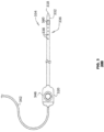
- the cardiac ablation system 100 may include a catheter 140, further described with reference to FIG. 3 .
- the catheter 140 may be configured to damage (ablate) tissue areas of an intra-body organ and/or to obtain biometric data including electric signals.
- the system 100 may include one or more probes 121, having shafts 122 that may be navigated by a physician or a user 130 into a body part, such as the heart 126, of a patient 128 lying on a table 129.
- the physician 130 may insert a shaft 122 through a sheath 123, while manipulating the distal end of the shafts 122 using a manipulator near the proximal end of the catheter 140 and/or while deflecting from the sheath 123.
- Inset 145 shows the catheter 140 in an enlarged view, inside a cardiac chamber of the heart 126.
- the catheter 140 may be fitted at the distal end of shaft 122.
- Catheter 140 may be inserted through sheath 123 in a collapsed state and may then be expanded within the heart 126.
- the catheter 140 may be configured to ablate tissue areas of a cardiac chamber of the heart 126.
- the catheter 140 may include at least one ablation electrode 147 coupled onto the body of the catheter.
- an ablation electrode 147 may be configured to provide energy to tissue areas of an intra-body organ such as the heart 126.
- the energy may be thermal energy and may cause damage to the tissue area starting from the surface of the tissue area and extending into the thickness of the tissue area.
- Other elements, such as electrodes or transducers may be part of the catheter and may be configured to ablate as well as to obtain biometric data.
- biometric data obtained by the catheter's elements, may represent information associated with LAT, electrical activity, topology, unipolar or bipolar voltage, dominant frequency, or impedance.
- LAT may represent a time at which an electrical activity has been measured at a certain location. The LAT may be calculated based on a normalized initial starting point.
- the electrical activity may be any applicable electrical signal that may be measured based on one or more thresholds. The electrical activity may be sensed and/or may be augmented (e.g., using filters to improve the signal to noise ratios).
- a topology may represent the physical structure of a body part or a portion of a body part or may correspond to changes in the physical structure between different portions of the body part or between different body parts.
- the console 124 of the system 100 may include a processing unit 141 that may comprise a front end and control components (e.g., a computer equipped with a multi-core processor).
- the console may also include memory 142, e.g., volatile and/or non-volatile memory and communications interface circuitry 138, e.g., for transmitting and receiving signals to and from the catheter 140.
- the console 124 may be configured to receive biometric data, and, then, to process the biometric data, to store the data for later processing, or to transmit the data to another system via a network.
- the system 100 may be modified to implement aspects disclosed herein. Aspects disclosed herein may be similarly applied using other system components and settings. Additionally, the system 100 may include additional components, such as elements for sensing electrical activity, wired or wireless connectors, processing units, or display devices.
- the console 124 may include real-time noise reduction circuitry typically configured as a field programmable gate array (FPGA), followed by an analog-to-digital (A/D) ECG (electrocardiograph) or EMG (electromyogram) signal conversion integrated circuit. The output of the A/D ECG or EMG circuit may be processed to perform methods disclosed herein.
- FPGA field programmable gate array
- A/D ECG electrocardiograph
- EMG electrocardiograph
- the console 124 may be connected, by a cable 139, to body surface electrodes 143, which may include adhesive skin patches that are affixed to the patient 128.
- the processing unit 141 in conjunction with a current tracking module, may determine position coordinates of the catheter 140 inside a body part (e.g., the heart 126) of the patient 128. The position coordinates may be based on impedances or electromagnetic fields measured between the body surface electrodes 143 and the electrode 147 or other electromagnetic components of the catheter 140. Additionally, or alternatively, location pads may be attached to the surface of the bed 129.
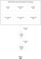
- FIG. 2 is a block diagram of an example system 200, deployable by the example cardiac ablation system of FIG. 1 , based on which one or more features of the disclosure may be implemented.
- the system 200 may include a monitoring and processing system 205, a local system 280, and a remote system 290.
- the monitoring and processing system 205 may represent the console 124 of system 100.
- the monitoring and processing system 205 may include a patient biometric sensor 210, a processor 220, memory 230, an input device 240, an output device 250, and a transceiver 260, i.e., a transmitter-receiver in communication with a network 270.
- the system 205 may continually or periodically monitor, store, process, and communicate, via the network 270, various patient biometrics.
- patient biometrics include electrical signals (e.g., ECG signals), anatomical images, blood pressure data, blood glucose data, and temperature data.
- the patient biometrics may be monitored and may be communicated for treatment of various diseases, such as cardiovascular diseases (e.g., arrhythmias, cardiomyopathy, and coronary artery disease) and autoimmune diseases (e.g., type I and type II diabetes).
- cardiovascular diseases e.g., arrhythmias, cardiomyopathy, and coronary artery disease
- autoimmune diseases e.g., type I and type II diabetes
- the monitoring and processing system 205 may represent a plurality of monitoring and processing systems 205 that may process biometric data of a patient in parallel and/or in communication with each other or in communication with a server via a network.
- One or more systems 205 may acquire or receive all or part of a patient's biometric data (e.g., electrical signals, anatomical images, blood pressure, temperature, blood glucose level, or other biometric data).
- the one or more systems 205 may also acquire or receive additional information associated with the acquired or received patient's biometric data from one or more other systems 205.
- the additional information may be, for example, diagnosis information and/or information obtained from a device such as a wearable device.
- Each monitoring and processing system 205 may process data acquired by it and may process data received from another system 205.
- the patient biometric sensor 210 may also include a catheter with one or more electrodes, a probe, a blood pressure cuff, a weight scale, a bracelet (e.g., a smart watch biometric tracker), a glucose monitor, a continuous positive airway pressure (CPAP) machine, or any other device that provides biometric data or other data concerning the patient health.
- a catheter with one or more electrodes e.g., a catheter with one or more electrodes, a probe, a blood pressure cuff, a weight scale, a bracelet (e.g., a smart watch biometric tracker), a glucose monitor, a continuous positive airway pressure (CPAP) machine, or any other device that provides biometric data or other data concerning the patient health.
- CPAP continuous positive airway pressure
- Input data may be fed to nodes in the first layer of a neural network so that each node in the first layer receives a weighted combination of the input data (or a weighted combination of a subset of the input data). Then, each node's inputted weighted combination is translated according to an activation function of the node, resulting in the node's output data.
- SA sino-atrial
- AV atrioventricular
- Bundle of His the cardiac muscle tissue that forms the walls of the ventricular and atrial cardiac chambers.
- Cardiac arrhythmias may be of a multiwavelet reentrant type that may be characterized by multiple asynchronous loops of electrical impulses that are scattered about the atrial chamber and are often self-propagating.
- cardiac arrhythmias may also have a focal origin, such as when an isolated region of tissue in an atrium fires autonomously in a rapid and repetitive fashion.
- VT is a tachycardia (fast heart rhythm) that originates in one of the ventricles of the heart. This is a potentially life-threatening arrhythmia because it may lead to ventricular fibrillation and sudden death.
- AF arrhythmia
- An irregular heartbeat that may result in from such conditions may last from minutes to weeks, or even years.
- AF is often a chronic condition that may lead to an increase in the risk of death, often due to strokes. Risk increases with age. Approximately 8% of people over 80 have some degree of AF. AF is often asymptomatic and, generally, is not in itself life-threatening, but it may result in palpitations, weakness, fainting, chest pain and congestive heart failure.
- a catheter ablation-based treatment may include mapping the electrical properties of the heart tissues, especially the endocardium and the heart volume, and selectively ablating cardiac tissue by the application of energy.
- Cardiac mapping for example, creating a map of electrical potentials of the wave propagation along the heart tissue (e.g., a voltage map) or a map of arrival times to various tissue location points (e.g., an LAT map) may be used for detecting local heart tissue dysfunction.
- Ablations such as those based on cardiac mapping, can cease or modify the propagation of unwanted electrical signals from one portion of the heart to another.
- Cardiac ablation and other cardiac electrophysiological procedures have become increasingly complex as clinicians treat challenging conditions such as AF and VT.
- the treatment of complex arrhythmias can now rely on the use of three-dimensional (3D) mapping systems in order to reconstruct the anatomy of the heart chamber of interest.
- 3D mapping systems in order to reconstruct the anatomy of the heart chamber of interest.
- cardiologists rely upon software such as the Complex Fractionated Atrial Electrograms (CFAE) module of the CARTO ® 3 3D mapping system, produced by Biosense Webster, Inc. (Diamond Bar, Calif.), to analyze intracardiac EGM signals and determine the ablation points for treatment of a broad range of cardiac conditions, including atypical atrial flutter and VT.
- the 3D maps can provide multiple measures of the electrophysiological properties of the tissue that represent the anatomical and functional substrate of these challenging arrhythmias.
- VT signals are induced in a patient.
- Pace-mapped signals are then obtained from multiple points within the ventricle, and the obtained pace-mapped signals are compared with the induced signals. Recognition of a high degree of correlation between the induced signals and one or more of the pace-mapped signals may identify arrhythmogenic foci, which may then be ablated.
- the pace-mapped signals in conventional systems are manually obtained by a physician through trial and error. The physician introduces a pacing catheter (or an electrode) into the heart chamber with which the physician applies electrical stimulation pulses to the myocardium at different locations.
- the machine learning models disclosed herein are trained to output data that may be utilized to predict the next cardiac location to be pace-mapped by the physician.
- the input data used for training are data from past pace-mapping procedures.
- the input data may comprise electrophysiological data of a cardiac arrhythmia (e.g., induced ECG signals), pace-mapped data (e.g., pace-mapped ECG signals obtained from a catheter when positioned at a plurality of cardiac locations), an LAT map, or a voltage map.
- input data used for training may also include data related to a physician's determination of whether the corresponding pace-mapped data sufficiently correlate with the electrophysiological data of the cardiac arrhythmia to be used as a site for ablation.
- the machine learning model Once the machine learning model is trained, it may be applied to provide a prediction for a cardiac location for a physician to use as the next pacing site. Such a prediction may provide a higher degree of certainty compared to the trial and error approach described above.
- the degree of correlation between the induced ECG signals 510 and the pace-mapped ECG signals 520 is indicative of the likelihood that the induced arrythmia in the patient was originated from the location in the heart 550 that was stimulated to result in the pace-mapped ECG signals 520.
- a pace map 540 may be computed for each patient i .
- Each element of the matrix may correspond to a location 550 in the heart at which place the myocardia has been stimulated and may represent a correlation between the induced ECG signals 510 and the pace-mapped ECG signals 520 that correspond to that location 550.
- a plurality of pace maps, P 1 , P 2 , ..., P n may be computed; each pace map P i may be represented by a 3-D matrix, where each matrix element may correspond to a 3D location on the myocardia surface (e.g., right ventricle myocardia) of a patient's heart.
- a neural network 410 may be trained to predict a pace map based on a partial map.
- each pace map P i is replicated M times.
- the replicas are called P i1 , P i2 , ..., P im .
- the correlation values in one or more randomly selected regions of the matrix, are replaced with a pre-determined value, e.g., an out-of-range number such as 999.
- a replaced value indicates that the correlation in that matrix element is unknown.
- the neural network is presented with pairs of matrixes, each pair includes a complete map P i and an incomplete map P im - that is, the training dataset is the example pairs ⁇ P 11 , P 1 ⁇ , ⁇ P 12 , P 1 ⁇ , ..., ⁇ P 1m , P 1 ⁇ , ⁇ P 21 , P 2 ⁇ , ⁇ P 22 , P 2 ⁇ , ..., ⁇ P 2m , P 2 ⁇ ..., ⁇ P n1 , P n ⁇ , ⁇ P n2 , P n ⁇ , ... ⁇ P nm , P n ⁇ .
- the neural network is then trained to give a predicted P i for each one of the inputs P i1 , P i2 , ..., P im . In this way, the neural network "learns" to predict the complete map (such as pace map 540) from a given incomplete map.
- FIG. 6 illustrates an example for training a model 600 to predict a complete pace map from an incomplete pace map, based on which one or more features of the disclosure may be implemented.
- FIG. 6 illustrates a replica P 11 , 610.1, of P 1 , 620.1 (e.g., pace map 540), and another replica P 12 , 610.2, of P 1 , 620.2 (e.g., pace map 540).
- elements of matrix P 11 and matrix P 12 were selected randomly and were replaced with an out-of-range number, e.g., 999, to indicate that the values of these selected elements are unknown.
- the neural network is trained to give the original map P 1 .
- the neural network is optimized so that a cost representing the difference between a replica P 1m and its pair P 1 is minimized. Setting the unknown correlation value to a number larger than a valid correlation value may contribute to a faster convergence of the neural network.
- the neural network is trained with as many example pairs 610 and 620 as possible.
- the trained neural network can be applied to complete unknown regions of a new pace map according to the "experience" it gained from pace maps it was trained on. Hence, the trained neural network may receive at its input a new incomplete pace map, and may provide at its output a predicted complete pace map.
- FIG. 7 illustrates another example for training a model 700 to predict a complete pace map from an incomplete pace map, based on which one or more features of the disclosure may be implemented.
- a second matrix is created, 710.2 or 710.4, with categorical element values (for example, 0 or 1) that indicate whether the element corresponds to a replaced or to an unknown element in 710.1 or 710.3, respectively.
- the second matrix may make the neural network converge faster.
- a training example 710 may include a replica matrix (e.g., 710.1 or 710.3) and a categorical matrix (e.g., 710.2 or 710.4) and a corresponding pair 720 (e.g., 720.1 or 720.2).
- the trained neural network may receive at its input a new incomplte pace map, and may provide at its output a predicted complte pace map.
- the system 100, 200 may now suggest to the physician a direction or a region in the heart to perform the next mappacing.
- the system's 100, 200 recommended direction or region may lead to a location with the highest colleration.
- the system's recommendation may be indicated by a visual or audiotory indication that points to the recommended direction or region.
- the visual indication may be represented by an arrow, a star, a pin, or any similar visual indication and may be overlayed on the image of the heart 530 presented on the system's display.
- the system may monitor the direction the physician is moving the catheter in, and may evaluate how successive that direction could end up being. Based on that evaluation, the system may provide a success indication as a percentage, a color (e.g., as green-yellow-red traffic lights), brightness, or a sound.
- a success indication as a percentage, a color (e.g., as green-yellow-red traffic lights), brightness, or a sound.
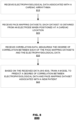
- FIG. 8 is a flow chart of an example method 800 for training a pace-mapping prediction model, based on which one or more features of the disclosure may be implemented.
- the pace mapping model may be based on a neural network, as described in reference to FIG. 4 .
- the method 800 may receive a training dataset based on which the pace-mapping model is trained; the training dataset may include data associated with pace-mapping procedures performed on patients in the past. Thus, for each such patient, the method 800 may receive, in step 810, electrophysiological data associated with a cardiac arrhythmia the patient endured. In step 820, the method 800 may receive pace-mapping datasets. Each dataset is obtained from an electrode (or a catheter) when positioned at a cardiac location in the patient's heart.
- the method 800 also may receive, in step 830, correlation data that measure the degree of correlation between each of the pace-mapping datasets and the electrophysiological data. Then, the training of the pace-mapping prediction model takes place, in step 840, based on the received training dataset.
- the pace-mapping prediction model is trained to predict a degree of correlation between electrophysiological data and a pace-mapping dataset of a new patient at a pace-mapping site.
- FIG. 9 is a flow chart of an example method 900 for applying a pace-mapping prediction model, based on which one or more features of the disclosure may be implemented.
- a trained pace-mapping prediction model as described with reference to FIG. 8 , for example, may be applied to a new patient under care during a pace-mapping procedure.
- the method 900 may receive as an input electrophysiological data associated with a cardiac arrhythmia that the patient under care has endured, in step 910. Additionally, the method 900 may receive as input a pace-mapping dataset, obtained from an electrode when positioned at a cardiac location in the heart of the patient, in step 920.
- the method 900 may feed the trained pace-mapping prediction model with the received input data, in step 930, to obtain a predicted degree of correlation between the electrophysiological data and the pace-mapping dataset.
- the predicted degree of correlation may be used to guide the physician performing the procedure in his search for a pace-mapping site that is likely to be the origin of the cardiac arrhythmia in the patient.
- the method 900 may predict, in step 940, based on the predicted degree of correlation, a cardiac location in the heart of the patient to be used as the next pace-mapping during the procedure.
- the method 900, in step 950 may track a movement of the electrode used in the procedure.
- step 960 based on the tracked movement and based on the predicted degree of correlation, the method 900 may evaluate whether the movement is in a direction that corresponds to an increasing degree of correlation.
- the method 900 may utilize multiple predicted values of degree of correlation, corresponding to multiple cardiac locations, by carrying out steps 910-930 multiple times.
- FIG. 10 is a flow chart of another example method 1000 for training a pace-mapping prediction model, based on which one or more features of the disclosure may be implemented.
- the pace mapping model may be based on a neural network, as described in reference to FIG. 4 .
- the method 1000 may receive a training dataset based on which the pace-mapping model is trained.
- the training dataset may include data of pace map pairs associated with pace-mapping procedures performed on patients in the past.
- the method 1000 may receive multiple pace map pairs, each pair includes a complete pace map, and an incomplete pace map (e.g., pair 610.1 and 620.1 or pair 610.2 and 620.2).
- the method 1000 may receive complete pace maps that each may comprise a correlation matrix.
- Each element of the matrix may correspond to one cardiac location in the patient's heart and may represent a degree of correlation between a pace-mapping dataset (corresponding to that one cardiac location) and the patient's electrophysiological data.
- the method 1000 may receive incomplete pace maps that each comprises a duplicate correlation matrix of that of a corresponding complete pace map, wherein one or more elements of the duplicate correlation matrix, selected randomly, are set to a pre-determined value, indicative of an unknown value.
- a categorical matrix associated with the incomplete pace map in the pair may also be received in step 1020.
- Each element value of the categorical matrix may indicate whether a corresponding element value in the associated incomplete pace map is set to the pre-determined value.
- the method 1000 may train the pace-mapping prediction model to receive an incomplete pace map of a new patient, containing known and unknown correlation matrix elements, and to provide a predicted complete pace map, containing predictions of the unknown correlation matrix elements.
- FIG. 11 is a flow chart of another example method 1100 for applying a pace-mapping prediction model, based on which one or more features of the disclosure may be implemented.
- a trained pace-mapping prediction model as described with reference to FIG. 10 , for example, may be applied to a patient under care during a pace-mapping procedure.
- the method 1100 in step 1110, may receive an incomplete pace map, generated during the procedure.
- the incomplete pace map may comprise a correlation matrix with known and unknown elements. Each of the known elements of the matrix may correspond to one cardiac location in the heart of the new patient and may represent a degree of correlation between the new patient's electrophysiological data and pace-mapping data obtained from an electrode when positioned at the one cardiac location in the heart of the new patient.
- the method 1100 may feed the pace-mapping prediction model with the new incomplete pace map to obtain a new predicted complete pace map, containing predictions of the unknown elements.
- the new predicted pace map may be used to guide the physician, performing the procedure, in his search for a pace-mapping site that is likely to be the origin of the cardiac arrhythmia in the patient.
- method 1100 in step 1130, may predict, based on the new predicted complete pace map, a cardiac location in the heart of the patient to be used as the next pace-mapping.
- method 1100, in step 1140 may track a movement of the electrode. Then, in step 1150, the method 1100 may evaluate, based on the tracked movement and based on the new predicted complete pace map, whether the movement is in a direction that corresponds to an increasing degree of correlation.
- the electrophysiological data associated with a cardiac arrhythmia endured by a patient may be induced.
- the patient may be experiencing VT that is induced by arrhythmogenic drugs, such as Isoproterenol, or by undergoing strenuous activity.
- training and applying the machine learning model may be performed by the systems described herein, 100 ( FIG. 1 ) or 200 ( FIG. 2 ), also representing the CARTO ® 3 3D mapping system, in real-time, on a server at the facility where the cardiac procedure is taking place, such as a hospital or medical facility, or at a remote location, such as in the cloud or at a training center.
- vendors of the systems, 100 ( FIG. 1 ) or 200 ( FIG. 2 ) may deliver such systems with a pre-trained pace-mapping prediction model. Hospitals may continue to train the system (e.g., to update the pace-mapping prediction model based on augmented or new training datasets).
- a single pace-mapping prediction model may be maintained for all hospitals, or for a group of hospitals, or every hospital may maintain its own pace-mapping prediction model.
- a machine learning model is utilized to identify sequences of paced pulses in a pacing procedure workflow and automatically measure an interval between the last paced pulse (in a pacing sequence) and the first native beat following the last paced pulse. Such interval measurement may be obtained from a time or a voltage caliper associated with particular ECG signal.
- Some electrophysiological procedures require pacing maneuvers for different arrhythmias (such as AF or VT) in which a chain of paced pulses may be generated.
- the pacing may be generated at one or more cardiac locations and may be measured at one or more cardiac locations and on body surface electrodes.
- the chain of paced pulses may be generated in equal time distances or may be generated in varying time distances.
- the system's operator may then open a time or a voltage caliper associated with a particular ECG signal and may measure the distance from the last paced pulse to the first native beat.
- a pacing maneuver may be useful in characterizing the cardiac tissue, deducing the presence of a short pathway, and identifying the location of a reentrant circuit.
- FIG. 12 illustrates an example ECG tracing 1200 of a pacing maneuver and time caliper measurements manually obtained by a physician, based on which one or more features of the disclosure may be implemented.
- a pacing maneuver may comprise a pacing sequence including pulses, each pulse has a time duration associated with it, e.g., 1210.1-1210.4.
- the last pulse has a 340 milliseconds (ms) duration time 1210.4.
- a pacing maneuver may also comprise native pulses having time durations associated with them 1210.5-1210.N.
- a post-pacing interval may be defined as the interval 1210.4 that extends from the initiation time of the last pulse 1220 to the time of a first native beat 1230 (henceforth a next native beat). Both the pacing sequence and the native beats may be associated with different cardiac locations and may have different durations, e.g., 1210.1-1210.N.
- a machine learning algorithm may be applied to detect, based on a pacing maneuver, interval measurements (of time calipers and/or voltage calipers) that may be accepted, rejected, or modified by a physician.
- a machine learning model is trained based on a training dataset, including pacing maneuvers and corresponding interval measurements, manually obtained from a physician.
- the pacing maneuvers and the corresponding interval measurements of the training dataset are associated with different cardiac locations and having different durations.
- interval measurements may include the start and the end of a period of a time (or a voltage), and may be represented by: 1) the post pacing interval (time between last pacing spike to the first native beat), e.g., 1210.4; 2) the pacing train properties (regular and irregular time intervals), e.g., 1210.1; 3) the tachycardia cycle length; 4) similar measurements on the Coronary Sinus catheter electrodes; 5) similar measurements on other catheters' electrodes; and 6) a combination thereof.
- the post pacing interval time between last pacing spike to the first native beat
- pacing train properties regular and irregular time intervals
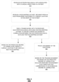
- FIGS. 13A-13B illustrate an example flow diagram depicting a training method ( FIG. 13A ) of a machine learning model and the machine learning model application ( FIG. 13B ), based on which one or more features of the disclosure may be implemented.
- Steps 1310-1330 describe the training phase of the machine learning algorithm.
- pacing maneuvers are received, each pacing maneuver may comprise a pacing sequence and a subsequent native beat associated with cardiac locations.
- interval measurements each corresponds to a pacing maneuver, are received.
- Each received interval measurement 1210.4 may be associated with a distance between the last paced pulse and a next native beat.
- a machine learning model may be trained based on the received pacing maneuvers 1310 and the corresponding received interval measurements 1320 to predict an interval measurement when presented with a new pacing maneuver.
- the machine learning model may be trained based on example pairs of training data - each example pair may include a pacing maneuver (including a pacing sequence and a subsequent native beat) and a corresponding interval measurement.
- a training pair may include a sequence of 300 ms, 290 ms, 280 ms, and 270 ms, and a corresponding interval measurement (e.g., a time caliper) that measures the distance between the last paced pulse 1220 and the next native beat 1230 - e.g., the distance measured from ⁇ 10 ms around the last paced pulse 1220 to ⁇ 10 ms around the next native beat 1230.
- the interval measurements may be determined manually by a physician based on respective pacing maneuvers.
- the machine learning model learns, for example, the physician's preference to adjust the caliper on the last paced pulse or on the mapping annotation at interval steps of ⁇ 10 ms.
- the machine learning model may receive as an input a pacing maneuver that may comprise a pacing sequence and a subsequent native beat. Based on the received pacing maneuver, as trained, the model may output, in step 1350, a prediction for an interval measurement. For example, if the machine learning model receives a sequence of 301 ms, 289 ms, 282 ms, and 269 ms, the machine learning model may predict an interval measurement (a caliper interval) associated with the distance 1210.4 between the last paced pulse and a next native beat.
- an interval measurement a caliper interval
- a physician may optionally accept, deny, or modify the predicted caliper interval.
- the predicted caliper interval may be stored in and/or may be used to update an EP cardiac map generated by the system 100 ( FIG. 1 ) or 200 ( FIG. 2 ).
- predicted interval measurements may be utilized to update an EP map to assist with characterizing tissue, identifying the presence of a short pathway, identifying the location of a reentrant circuit, etc.
- an element of the EP map may represent a caliper interval at a corresponding pacing location in the heart.
- an EP map may be color-coded to identify any of the foregoing.
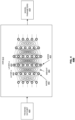
- FIG. 14 illustrates a functional block diagram 1400 of an example RNN 1420, based on which one or more features of the disclosure may be implemented.
- Various machine learning models may be applied to implement the features described in reference to FIGS. 13A-B , such as those neural networks described with reference to FIGS. 4 and 14 .
- an RNN 1420 may be used.
- an RNN 1420 may receive paced pulses and native beats as input data 1410.
- the RNN 1420 is trained to produce, based on the input data 1410, an output 1430, such as interval measurement between the last paced pulse to the mapping annotation (i.e., native beat).
- the more input data 1410 received by the RNN 1420 the more accurate the output 1430 may be.
- the output of the RNN 1420 may be used to train the RNN 1400, as illustrated by arrow 1440 in FIG. 14 .
- the output 1430 may be used as an input 1410 to train the RNN 1420.
- training and applying a machine learning model may be performed by the systems described herein, 100 ( FIG. 1 ) or 200 ( FIG. 2 ), also representing a Mapping System, in real-time, on a server at the facility where the cardiac procedure is taking place, such as a hospital or medical facility, or at a remote location, such as in the cloud or at a training center.
- the methods, processes, modules, and systems described herein may be implemented in a computer program, software, or firmware incorporated in a computer-readable medium for execution by a computer or processor.
- Examples of computer-readable media include electronic signals (transmitted over wired or wireless connections) and computer-readable storage media.
- Examples of computer-readable storage media include, but are not limited to, read only memory (ROM), random access memory (RAM), a register, cache memory, semiconductor memory devices, magnetic media such as internal hard disks and removable disks, magnetooptical media, and optical media such as CD-ROM disks, and digital versatile disks (DVDs).
- ROM read only memory
- RAM random access memory
- a processor in association with software may be used to implement a radio frequency transceiver for use in a WTRU, UE, terminal, base station, RNC, or any host computer.
Landscapes
- Health & Medical Sciences (AREA)
- Life Sciences & Earth Sciences (AREA)
- Engineering & Computer Science (AREA)
- Medical Informatics (AREA)
- Public Health (AREA)
- Biomedical Technology (AREA)
- General Health & Medical Sciences (AREA)
- Surgery (AREA)
- Physics & Mathematics (AREA)
- Pathology (AREA)
- Veterinary Medicine (AREA)
- Animal Behavior & Ethology (AREA)
- Molecular Biology (AREA)
- Heart & Thoracic Surgery (AREA)
- Biophysics (AREA)
- Cardiology (AREA)
- Physiology (AREA)
- Artificial Intelligence (AREA)
- Epidemiology (AREA)
- Primary Health Care (AREA)
- Computer Vision & Pattern Recognition (AREA)
- Psychiatry (AREA)
- Signal Processing (AREA)
- Databases & Information Systems (AREA)
- Data Mining & Analysis (AREA)
- Plasma & Fusion (AREA)
- Nuclear Medicine, Radiotherapy & Molecular Imaging (AREA)
- Otolaryngology (AREA)
- Fuzzy Systems (AREA)
- Mathematical Physics (AREA)
- Evolutionary Computation (AREA)
- Business, Economics & Management (AREA)
- General Business, Economics & Management (AREA)
- Human Computer Interaction (AREA)
- Physical Education & Sports Medicine (AREA)
- Measurement And Recording Of Electrical Phenomena And Electrical Characteristics Of The Living Body (AREA)
- Electrotherapy Devices (AREA)
Applications Claiming Priority (3)
| Application Number | Priority Date | Filing Date | Title |
|---|---|---|---|
| US202063062715P | 2020-08-07 | 2020-08-07 | |
| US17/391,249 US12414731B2 (en) | 2020-08-07 | 2021-08-02 | System and method to detect and identify cardiac pace-mapping sites and pacing maneuvers |
| EP21190023.8A EP3951788B1 (fr) | 2020-08-07 | 2021-08-06 | Système de détection et d'identification de sites de cartographie de stimulation cardiaque |
Related Parent Applications (2)
| Application Number | Title | Priority Date | Filing Date |
|---|---|---|---|
| EP21190023.8A Division-Into EP3951788B1 (fr) | 2020-08-07 | 2021-08-06 | Système de détection et d'identification de sites de cartographie de stimulation cardiaque |
| EP21190023.8A Division EP3951788B1 (fr) | 2020-08-07 | 2021-08-06 | Système de détection et d'identification de sites de cartographie de stimulation cardiaque |
Publications (2)
| Publication Number | Publication Date |
|---|---|
| EP4495947A2 true EP4495947A2 (fr) | 2025-01-22 |
| EP4495947A3 EP4495947A3 (fr) | 2025-04-16 |
Family
ID=77249699
Family Applications (3)
| Application Number | Title | Priority Date | Filing Date |
|---|---|---|---|
| EP24217323.5A Pending EP4495946A3 (fr) | 2020-08-07 | 2021-08-06 | Système et procédé pour détecter et identifier des sites de cartographie cardiaque et des man uvres de stimulation |
| EP24217328.4A Pending EP4495947A3 (fr) | 2020-08-07 | 2021-08-06 | Système et procédé pour détecter et identifier des sites de cartographie cardiaque et des man uvres de stimulation |
| EP21190023.8A Active EP3951788B1 (fr) | 2020-08-07 | 2021-08-06 | Système de détection et d'identification de sites de cartographie de stimulation cardiaque |
Family Applications Before (1)
| Application Number | Title | Priority Date | Filing Date |
|---|---|---|---|
| EP24217323.5A Pending EP4495946A3 (fr) | 2020-08-07 | 2021-08-06 | Système et procédé pour détecter et identifier des sites de cartographie cardiaque et des man uvres de stimulation |
Family Applications After (1)
| Application Number | Title | Priority Date | Filing Date |
|---|---|---|---|
| EP21190023.8A Active EP3951788B1 (fr) | 2020-08-07 | 2021-08-06 | Système de détection et d'identification de sites de cartographie de stimulation cardiaque |
Country Status (5)
| Country | Link |
|---|---|
| US (1) | US12414731B2 (fr) |
| EP (3) | EP4495946A3 (fr) |
| JP (1) | JP7827244B2 (fr) |
| CN (1) | CN114067987A (fr) |
| IL (1) | IL285347B2 (fr) |
Families Citing this family (6)
| Publication number | Priority date | Publication date | Assignee | Title |
|---|---|---|---|---|
| US12144636B2 (en) | 2020-07-08 | 2024-11-19 | Biosense Webster (Israel) Ltd. | System and method to determine the location of a catheter |
| US20220068483A1 (en) * | 2020-09-01 | 2022-03-03 | Biosense Webster (Israel) Ltd. | Arrhythmia classification for cardiac mapping |
| US12161396B2 (en) * | 2021-10-19 | 2024-12-10 | Riccardo Cappato | System, device, and method for determining location of arrhythmogenic foci |
| WO2024009220A1 (fr) * | 2022-07-05 | 2024-01-11 | Biosense Webster (Israel) Ltd. | Système et procédé pour déterminer l'emplacement d'un cathéter |
| WO2026005717A1 (fr) * | 2024-06-26 | 2026-01-02 | Cmkl University | Cartographie du cœur pour un processus d'ablation cardiaque à l'aide d'une intelligence artificielle |
| CN120951802B (zh) * | 2025-09-17 | 2026-02-24 | 河南省贝威科技有限公司 | 一种基于大数据分析的心脏电生理动态建模方法及系统 |
Citations (1)
| Publication number | Priority date | Publication date | Assignee | Title |
|---|---|---|---|---|
| US7907994B2 (en) | 2007-01-11 | 2011-03-15 | Biosense Webster, Inc. | Automated pace-mapping for identification of cardiac arrhythmic conductive pathways and foci |
Family Cites Families (3)
| Publication number | Priority date | Publication date | Assignee | Title |
|---|---|---|---|---|
| JP2520331B2 (ja) | 1991-03-25 | 1996-07-31 | 株式会社エイ・ティ・アール自動翻訳電話研究所 | ニュ―ラルネットワ―クの学習方法 |
| US8224443B2 (en) * | 2007-05-08 | 2012-07-17 | Cardiac Pacemakers, Inc. | Method for controlling pacemaker therapy |
| EP3905952B1 (fr) | 2018-12-31 | 2025-09-03 | The Regents of the University of California | Simulations cardiaques informatiques améliorées |
-
2021
- 2021-08-02 US US17/391,249 patent/US12414731B2/en active Active
- 2021-08-03 IL IL285347A patent/IL285347B2/en unknown
- 2021-08-06 EP EP24217323.5A patent/EP4495946A3/fr active Pending
- 2021-08-06 EP EP24217328.4A patent/EP4495947A3/fr active Pending
- 2021-08-06 EP EP21190023.8A patent/EP3951788B1/fr active Active
- 2021-08-06 JP JP2021129636A patent/JP7827244B2/ja active Active
- 2021-08-09 CN CN202110907181.6A patent/CN114067987A/zh active Pending
Patent Citations (1)
| Publication number | Priority date | Publication date | Assignee | Title |
|---|---|---|---|---|
| US7907994B2 (en) | 2007-01-11 | 2011-03-15 | Biosense Webster, Inc. | Automated pace-mapping for identification of cardiac arrhythmic conductive pathways and foci |
Also Published As
| Publication number | Publication date |
|---|---|
| IL285347A (en) | 2022-03-01 |
| EP3951788B1 (fr) | 2025-01-15 |
| US12414731B2 (en) | 2025-09-16 |
| CN114067987A (zh) | 2022-02-18 |
| EP4495946A3 (fr) | 2025-04-16 |
| IL285347B1 (en) | 2025-08-01 |
| JP2022031248A (ja) | 2022-02-18 |
| EP4495946A2 (fr) | 2025-01-22 |
| IL285347B2 (en) | 2025-12-01 |
| JP7827244B2 (ja) | 2026-03-10 |
| EP3951788A1 (fr) | 2022-02-09 |
| EP4495947A3 (fr) | 2025-04-16 |
| EP3951788C0 (fr) | 2025-01-15 |
| US20220039730A1 (en) | 2022-02-10 |
Similar Documents
| Publication | Publication Date | Title |
|---|---|---|
| EP3951788B1 (fr) | Système de détection et d'identification de sites de cartographie de stimulation cardiaque | |
| EP3960085B1 (fr) | Classification d'arythmie pour la cartographie cardiaque | |
| EP3951790A1 (fr) | Appareil pour le traitement d'arythmies cardiaques utilisant un algorithme d'apprentissage machine pour optimiser le calcul d'un indice d'ablation | |
| US12165324B2 (en) | Automatically identifying scar areas within organic tissue using multiple imaging modalities | |
| US20220181025A1 (en) | Setting an automatic window of interest based on a learning data analysis | |
| US12350073B2 (en) | Signal and correction processing for anatomical structure mapping data | |
| US20220068479A1 (en) | Separating abnormal heart activities into different classes | |
| EP4166082B1 (fr) | Liaison de liste de points à une anatomie tridimensionnelle | |
| EP4014871A1 (fr) | Mesure et affichage automatiques d'intervalle de post-stimulation |
Legal Events
| Date | Code | Title | Description |
|---|---|---|---|
| PUAI | Public reference made under article 153(3) epc to a published international application that has entered the european phase |
Free format text: ORIGINAL CODE: 0009012 |
|
| STAA | Information on the status of an ep patent application or granted ep patent |
Free format text: STATUS: THE APPLICATION HAS BEEN PUBLISHED |
|
| AC | Divisional application: reference to earlier application |
Ref document number: 3951788 Country of ref document: EP Kind code of ref document: P |
|
| AK | Designated contracting states |
Kind code of ref document: A2 Designated state(s): AL AT BE BG CH CY CZ DE DK EE ES FI FR GB GR HR HU IE IS IT LI LT LU LV MC MK MT NL NO PL PT RO RS SE SI SK SM TR |
|
| REG | Reference to a national code |
Ref country code: DE Ref legal event code: R079 Free format text: PREVIOUS MAIN CLASS: G16H0040630000 Ipc: G16H0020300000 |
|
| PUAL | Search report despatched |
Free format text: ORIGINAL CODE: 0009013 |
|
| AK | Designated contracting states |
Kind code of ref document: A3 Designated state(s): AL AT BE BG CH CY CZ DE DK EE ES FI FR GB GR HR HU IE IS IT LI LT LU LV MC MK MT NL NO PL PT RO RS SE SI SK SM TR |
|
| RIC1 | Information provided on ipc code assigned before grant |
Ipc: A61B 34/20 20160101ALI20250310BHEP Ipc: A61B 34/10 20160101ALI20250310BHEP Ipc: A61B 18/14 20060101ALI20250310BHEP Ipc: A61B 5/367 20210101ALI20250310BHEP Ipc: A61B 5/287 20210101ALI20250310BHEP Ipc: A61B 5/06 20060101ALI20250310BHEP Ipc: G16H 50/20 20180101ALI20250310BHEP Ipc: G16H 40/63 20180101ALI20250310BHEP Ipc: A61B 5/00 20060101ALI20250310BHEP Ipc: G16H 20/30 20180101AFI20250310BHEP |
|
| STAA | Information on the status of an ep patent application or granted ep patent |
Free format text: STATUS: REQUEST FOR EXAMINATION WAS MADE |
|
| 17P | Request for examination filed |
Effective date: 20251016 |
|
| GRAP | Despatch of communication of intention to grant a patent |
Free format text: ORIGINAL CODE: EPIDOSNIGR1 |
|
| STAA | Information on the status of an ep patent application or granted ep patent |
Free format text: STATUS: GRANT OF PATENT IS INTENDED |