EP4496109A1 - Ensemble électrode doté d'une structure de jonction de languette d'électrode et batterie secondaire le comprenant - Google Patents
Ensemble électrode doté d'une structure de jonction de languette d'électrode et batterie secondaire le comprenant Download PDFInfo
- Publication number
- EP4496109A1 EP4496109A1 EP23865895.9A EP23865895A EP4496109A1 EP 4496109 A1 EP4496109 A1 EP 4496109A1 EP 23865895 A EP23865895 A EP 23865895A EP 4496109 A1 EP4496109 A1 EP 4496109A1
- Authority
- EP
- European Patent Office
- Prior art keywords
- electrode
- electrode tabs
- type
- tabs
- tab
- Prior art date
- Legal status (The legal status is an assumption and is not a legal conclusion. Google has not performed a legal analysis and makes no representation as to the accuracy of the status listed.)
- Pending
Links
Images


Classifications
-
- H—ELECTRICITY
- H01—ELECTRIC ELEMENTS
- H01M—PROCESSES OR MEANS, e.g. BATTERIES, FOR THE DIRECT CONVERSION OF CHEMICAL ENERGY INTO ELECTRICAL ENERGY
- H01M50/00—Constructional details or processes of manufacture of the non-active parts of electrochemical cells other than fuel cells, e.g. hybrid cells
- H01M50/10—Primary casings; Jackets or wrappings
- H01M50/102—Primary casings; Jackets or wrappings characterised by their shape or physical structure
- H01M50/105—Pouches or flexible bags
-
- H—ELECTRICITY
- H01—ELECTRIC ELEMENTS
- H01M—PROCESSES OR MEANS, e.g. BATTERIES, FOR THE DIRECT CONVERSION OF CHEMICAL ENERGY INTO ELECTRICAL ENERGY
- H01M50/00—Constructional details or processes of manufacture of the non-active parts of electrochemical cells other than fuel cells, e.g. hybrid cells
- H01M50/50—Current conducting connections for cells or batteries
- H01M50/531—Electrode connections inside a battery casing
- H01M50/536—Electrode connections inside a battery casing characterised by the method of fixing the leads to the electrodes, e.g. by welding
-
- H—ELECTRICITY
- H01—ELECTRIC ELEMENTS
- H01M—PROCESSES OR MEANS, e.g. BATTERIES, FOR THE DIRECT CONVERSION OF CHEMICAL ENERGY INTO ELECTRICAL ENERGY
- H01M50/00—Constructional details or processes of manufacture of the non-active parts of electrochemical cells other than fuel cells, e.g. hybrid cells
- H01M50/50—Current conducting connections for cells or batteries
- H01M50/531—Electrode connections inside a battery casing
- H01M50/533—Electrode connections inside a battery casing characterised by the shape of the leads or tabs
-
- H—ELECTRICITY
- H01—ELECTRIC ELEMENTS
- H01M—PROCESSES OR MEANS, e.g. BATTERIES, FOR THE DIRECT CONVERSION OF CHEMICAL ENERGY INTO ELECTRICAL ENERGY
- H01M50/00—Constructional details or processes of manufacture of the non-active parts of electrochemical cells other than fuel cells, e.g. hybrid cells
- H01M50/50—Current conducting connections for cells or batteries
- H01M50/531—Electrode connections inside a battery casing
- H01M50/534—Electrode connections inside a battery casing characterised by the material of the leads or tabs
-
- H—ELECTRICITY
- H01—ELECTRIC ELEMENTS
- H01M—PROCESSES OR MEANS, e.g. BATTERIES, FOR THE DIRECT CONVERSION OF CHEMICAL ENERGY INTO ELECTRICAL ENERGY
- H01M50/00—Constructional details or processes of manufacture of the non-active parts of electrochemical cells other than fuel cells, e.g. hybrid cells
- H01M50/50—Current conducting connections for cells or batteries
- H01M50/531—Electrode connections inside a battery casing
- H01M50/54—Connection of several leads or tabs of plate-like electrode stacks, e.g. electrode pole straps or bridges
-
- H—ELECTRICITY
- H01—ELECTRIC ELEMENTS
- H01M—PROCESSES OR MEANS, e.g. BATTERIES, FOR THE DIRECT CONVERSION OF CHEMICAL ENERGY INTO ELECTRICAL ENERGY
- H01M2220/00—Batteries for particular applications
- H01M2220/10—Batteries in stationary systems, e.g. emergency power source in plant
-
- H—ELECTRICITY
- H01—ELECTRIC ELEMENTS
- H01M—PROCESSES OR MEANS, e.g. BATTERIES, FOR THE DIRECT CONVERSION OF CHEMICAL ENERGY INTO ELECTRICAL ENERGY
- H01M2220/00—Batteries for particular applications
- H01M2220/20—Batteries in motive systems, e.g. vehicle, ship, plane
-
- H—ELECTRICITY
- H01—ELECTRIC ELEMENTS
- H01M—PROCESSES OR MEANS, e.g. BATTERIES, FOR THE DIRECT CONVERSION OF CHEMICAL ENERGY INTO ELECTRICAL ENERGY
- H01M50/00—Constructional details or processes of manufacture of the non-active parts of electrochemical cells other than fuel cells, e.g. hybrid cells
- H01M50/10—Primary casings; Jackets or wrappings
- H01M50/172—Arrangements of electric connectors penetrating the casing
-
- Y—GENERAL TAGGING OF NEW TECHNOLOGICAL DEVELOPMENTS; GENERAL TAGGING OF CROSS-SECTIONAL TECHNOLOGIES SPANNING OVER SEVERAL SECTIONS OF THE IPC; TECHNICAL SUBJECTS COVERED BY FORMER USPC CROSS-REFERENCE ART COLLECTIONS [XRACs] AND DIGESTS
- Y02—TECHNOLOGIES OR APPLICATIONS FOR MITIGATION OR ADAPTATION AGAINST CLIMATE CHANGE
- Y02E—REDUCTION OF GREENHOUSE GAS [GHG] EMISSIONS, RELATED TO ENERGY GENERATION, TRANSMISSION OR DISTRIBUTION
- Y02E60/00—Enabling technologies; Technologies with a potential or indirect contribution to GHG emissions mitigation
- Y02E60/10—Energy storage using batteries
Definitions
- the present invention relates to an electrode assembly having an electrode tab bonding structure and a secondary battery including the same, and more particularly, to an electrode assembly having an electrode tab bonding structure and including a resin collector having metal layers deposited on a polymer layer, in which electrode tabs of different shapes are alternately stacked so that a conduction structure is formed, and in which conduction of electrons is facilitated in the direction of the electrode stacking even in the presence of a polymer layer, and a secondary battery including the electrode assembly.
- secondary batteries with high energy density, discharge voltage, and good output stability.
- secondary batteries include lithium-based secondary batteries such as lithium-sulfur batteries, lithium ion batteries, and lithium ion polymer batteries.
- the above-mentioned secondary batteries can be categorized into cylindrical, prismatic, pouch-type, etc., according to their shape, and among them, interest in and demand for pouch-type battery cells are gradually increasing.
- Pouch-type battery cells can be stacked with high degree of integration and have a high energy density per weight, and are also inexpensive and easy to deform. Therefore, pouch-type battery cells can be fabricated into shapes and sizes that are applicable to a variety of mobile devices and automobiles.
- These pouch-type battery cells typically have a stacked structure of a number of unit cells each of which includes an anode, a cathode, and a separator interposed between the anode and cathode (i.e, electrode assembly or stack cells), which can be produced by housing the electrode assembly in a battery case and then injecting an electrolyte, or by having a solid electrolyte within the electrode assembly from the outset.
- an anode active material or a cathode active material is applied and positioned on the electrode collector for conduction of current, and in recent years, to increase the energy density and improve the stability of the battery.
- a lightweight resin collector with a metal layer deposited on a polymer layer made of polyimide (PI) or polyethylene terephthalate (PET) has been developed and applied to batteries.
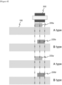
- FIG. 1 is a front view of a structure in which electrode tabs and a lead tab of a resin collector are bonded in a conventional manner, viewed from the withdrawal direction of the electrode tabs; and
- FIG. 2 is a plan view schematically illustrating a stacking and bonding position of the electrode tabs and the lead tab of the resin collector when the electrode tabs and lead tab are bonded together in a conventional manner.
- the electrode tabs and lead tab of the resin collector are simply stacked and bonded in a conventional manner, as shown in FIGS. 1 and 2 .
- an electrode assembly having an electrode tab bonding structure and including a resin collector having metal layers deposited on a polymer layer, in which electrode tabs of different shapes are alternately stacked so that a conduction structure is formed, and in which conduction of electrons is facilitated in the direction of the electrode stacking even in the presence of a polymer layer, and a secondary battery including the electrode assembly.
- the present invention provides an electrode assembly, comprising: A-type electrode tabs located bias to the left of a center line of a longitudinal direction of a center bonding portion between electrode tabs; and B-type electrode tabs located bias to the right of the center line, wherein the A-type electrode tabs and the B-type electrode tabs are alternately positioned, and the A-type electrode tabs and the B-type electrode tabs are partially overlapped to form the center bonding portion, wherein remaining portions of the A-type electrode tabs and the B-type electrode tabs that do not form the center bonding portion form a structure in which side bonding portions each with a same type of electrode tabs are formed, and wherein the A-type electrode tabs and B-type electrode tabs each have a structure in which a polymer layer is interposed between two metal layers.
- the present invention provides a secondary battery comprising: the electrode assembly having the electrode tab bonding structure; and an accommodating case for receiving the electrode assembly.
- an electrode assembly having a bonding structure of electrode tabs and a secondary battery including the same in which, electrode tabs of different shapes are stacked alternately in the electrode assembly so that a conduction structure is formed in the electrode assembly having a resin collector with metal layers deposited on polymer layers so as to provide a bonding structure for the electrode tabs, in which the conduction of electrons is facilitated in the direction of the electrode stacking even in the presence of polymer layers.
- FIG. 3 is a front view of a structure in which electrode tabs of different shapes are alternately stacked so that a conductive structure is formed according to an embodiment of the present invention, viewed from a withdrawal direction of the electrode tabs; and
- FIG. 4 is a plan view schematically illustrating a stacking and bonding position of the electrode tabs and lead tab of a resin collector when the electrode tabs and lead tab are bonded, according to an embodiment of the present invention.
- An electrode assembly having a bonding structure of electrode tabs includes A-type electrode tabs 200a, 200a' located bias to the left of a longitudinal centerline of a center bonding portion between electrode tabs; B-type electrode tabs 200b, 200b' located bias to the right of the centerline, wherein the A-type electrode tabs 200a, 200a' and B-type electrode tabs 200b, 200b' are alternately positioned, and the A-type electrode tabs 200a, 200a' and B-type electrode tabs 200b, 200b' are partially overlapped to form the center bonding portion, the remaining portions of the A-type electrode tabs 200a, 200a' and B-type electrode tabs 200b, 200b' that do not form the center bonding portion form a structure in which side bonding portions each with a same type of electrode tabs 200a, 200a' and 200b, 200b' are formed, and wherein the A type electrode tabs 200a, 200a' and B type electrode tabs 200
- pouch-type battery cells typically have a stacked structure of multiple unit cells each of which includes an anode, a cathode, and a separator interposed between the anode and cathode (i.e., an electrode assembly or stack cells), which can be produced by accommodating the electrode assembly in a battery case and then injecting an electrolyte, or by having a solid electrolyte within the electrode assembly from the outset.
- an electrode assembly or stack cells within the electrode assembly, an anode active material or a cathode active material is applied and positioned on the electrode collector for the conduction of current.
- the present inventors have invented an electrode assembly that can improve the performance of a battery by increasing the energy density and stability of the battery, by applying a resin collector coated with metal layers on polymer layers as a collector, and by facilitating the conduction of electrons in the direction of electrode stacking even in the presence of the polymer layers, thereby eliminating or minimizing the resistance difference between the electrodes.
- the present invention has a key feature in the structure or shape of electrode tabs 200 that extends and protrudes from a collector (specifically, a resin collector containing a non-conductive polymer layer and a conductive metal layer) included in a unit cell 100 and is bonded to a lead tab 300 made of metal. That is, by forming the electrode tabs 200 in the shape shown in FIG. 3 , the metal layers contained in each of the plurality of electrode tabs 200 can contact each other, and accordingly, facilitate the conduction of electrons in the direction of electrode stacking, thereby eliminating or minimizing the resistance difference between the electrodes and improving the performance of the battery compared to the conventional case (the arrows in FIG. 3 indicate the conduction path of electrons).
- the A-type electrode tabs 200a, 200a' and the B-type electrode tabs 200b, 200b' have a shape that extends and protrudes from the collector included in each unit cell 100 of the electrode assembly. Therefore, the collector also has a structure that has a polymer layer interposed between two metal layers.
- a lead tab 300 is arranged at the outermost part of the electrode tab assembly that includes the A-type electrode tabs 200a, 200a' and B-type electrode tabs 200b, 200b' or between the electrode tab assemblies.
- the A-type electrode tabs 200a, 200a' have, based on the vertical cross-section viewed from the direction where the electrode tabs 200 are drawn out as shown in FIG. 3 , one end positioned to coincide with one end of the lead tab 300 and the other end positioned between the other end and the center portion of the lead tab 300, although not limited thereto.
- the B-type electrode tabs 200b, 200b' can be positioned in a shape that is symmetrical to the A-type electrode tabs 200a, 200a' as shown in FIG. 3 , although not limited thereto.
- the A-type electrode tabs 200a, 200a' and the B-type electrode tabs 200b, 200b' have a shape that are alternately stacked one by one as shown in FIGS. 3 and 4 .
- the A-type electrode tabs 200a, 200a' and the B-type electrode tabs 200b, 200b' are partially overlapped to form a center bonding portion.
- same type of electrode tabs 200a, 200a', or 200b, 200b' should have a shape that is pressed in units of two sheets in the direction of one end of the lead tab 300. At this time, one sheet of a different type of electrode tab is interposed between them. Therefore, by forming a side bonding portion by pressing the same type of electrode tabs together, they form a shape that interposes a different type of electrode tab between them, and the metal layers contained in each of the same type of electrode tabs contact each other at the side bonding portion. At this time, a leading edge of the side bonding portion can be positioned to coincide with one end of the lead tab as shown in FIG. 3 , although not limited thereto.
- the metal layers contained in each of the same type of electrode tabs contact each other at the portion that has the pressed shape (side bonding portion). Also, because one sheet of a different type of electrode tab is interposed between the same type of electrode tabs 200a, 200a', or 200b, 200b' by way of the pressed shape, the metal layers of different types of electrode tabs also face and contact each other.
- the same type of electrode tabs contact each other, and by contacting the metal layers through the center bonding portion, different types of electrode tabs (for example, 200a and 200b, 200b and 200a', 200a' and 200b') contact each other, thereby forming a continuous conduction structure between all the electrode tabs including the A-type electrode tabs 200a, 200a' and the B-type electrode tabs 200b, 200b'. And accordingly, a continuous conduction structure is formed between the lead tab 300 and all the electrode tabs, and the conduction of electrons is smoothly performed. Therefore, one or more of the A-type electrode tabs 200a, 200a' and the B-type electrode tabs 200b, 200b' should be provided in even numbers.
- the A-type electrode tabs 200a, 200a' and the B-type electrode tabs 200b, 200b' may be each overlapped with each other by a width of more than 50% and less than or equal to 80%, preferably 60% to 80%, more preferably 70% to 80%, based on the width of the lead tab 300. If the width of each of the A-type electrode tabs 200a, 200a' and the B-type electrode tabs 200b, 200b' is less than or equal to 50% based on the width of the lead tab 300, it may not be easy to facilitate contact between different types of electrode tabs.
- the center bonding portion may not be formed, and it may be difficult for the A-type electrode tabs 200a, 200a' and the B-type electrode tabs 200b, 200b' to contact through the metal layer. Furthermore, if the width of each of the A-type electrode tabs 200a, 200a' and the B-type electrode tabs 200b, 200b' exceeds 80% based on the width of the lead tab 300, unnecessary parts that do not contact between different types of electrode tabs may occur, and this may be disadvantageous in terms of cost.
- the lead tab 300 may only physically contact the A-type electrode tab 200a, but as shown in FIG. 3 , if the lead tab 300 physically contacts both the A-type electrode tab 200a and the B-type electrode tab 200b, the conduction of electrons can be more smooth. In other words, it is preferable that the lead tab 300 contacts one of the A-type electrode tabs and one of the B-type electrode tabs that are positioned to face each other. And at the same time, by contacting the lead tab 300 to the entire end cross-section of the unpressed A-type electrode tab 200a as shown in FIG. 3 , the conduction of electrons can be more smooth.
- FIG. 3 shows an electrode assembly consisting of only two sheets of A-type electrode tabs 200a, 200a' and two sheets of B-type electrode tabs 200b, 200b'.
- the two sheets of A-type electrode tabs 200a, 200a' are denoted as the first electrode tab 200a and the third electrode tab 200a'
- the two sheets of B-type electrode tabs 200b, 200b' are denoted as the second electrode tab 200b and the fourth electrode tab 200b'.
- the electrode tabs included in the electrode assembly comprises:
- the A-type electrode tabs include the first electrode tab and the third electrode tab and the B-type electrode tabs include the second electrode tab and the fourth electrode tab, the first electrode tab contacts the lead tab face-to-face, and the second electrode tab, the third electrode tab, and the fourth electrode tab are sequentially positioned on the other side of the first electrode tab that does not face the lead tab)
- the one end of the first electrode tab 200a that is positioned to coincide with one end of the lead tab 300 and the one end of the third electrode tab 200a' are pressed in a shape that interposes the second electrode tab 200b between them, and the metal layer of the first electrode tab 200a and the metal layer of the third electrode tab 200a' contact at the pressed portion. That is, by way of a pressed shape at the one end of the first electrode tab 200a and the one end of the third electrode tab 200a', the metal layers facing each other of the first electrode tab 200a and the third electrode tab 200a' contact each other, and the metal layers not facing each other of the first electrode tab 200a and the third electrode tab 200a' can also contact each other.
- the one end of the second electrode tab 200b that is positioned to coincide with the other end of the lead tab 300 and the one end of the fourth electrode tab 200b' are pressed in a shape that interposes the third electrode tab 200a' between them, and the metal layer of the second electrode tab 200b and the metal layer of the fourth electrode tab 200b' contact at the pressed portion. That is, by having a pressed shape at the one end of the second electrode tab 200b and the one end of the fourth electrode tab 200b', the metal layers facing each other of the second electrode tab 200b and the fourth electrode tab 200b' contact each other, and the metal layers not facing each other of the second electrode tab 200b and the fourth electrode tab 200b' can also contact each other.
- the lead tab 300 may only physically contact the first electrode tab 200a, but as shown in FIG. 3 , if the lead tab 300 physically contacts both the first electrode tab 200a and the second electrode tab 200b, the conduction of electrons can be more smooth. And at the same time, by contacting the lead tab 300 to the entire end cross-section of the unpressed first electrode tab 200a as shown in FIG. 3 , the conduction of electrons can be more smooth.
- an electrode assembly consisting of four electrode tabs was exemplified, but it will be readily understood to those skilled in the art that a plurality of electrode tabs can be additionally stacked. For example, on the other side of the fourth electrode tab 200b' that does not face the third electrode tab 200a', a plurality of A-type electrode tabs and B-type electrode tabs can be alternately included.
- the secondary battery includes the electrode assembly of the present invention described above and a case that accommodates the electrode assembly.
- the secondary battery is not limited to any particular use.
- the secondary battery may be any battery that can accommodate the electrode assembly in a storage case such as a pouch, but it may be desirable to use a lithium-based secondary battery.
- the cathode active material may include sulfur, including sulfur-carbon composites that also include carbon materials.
- examples of cathode active materials include lithium cobalt oxide (LiCoO 2 ), lithium nickel oxide (LiNiO 2 ), lithium manganese oxide (LiMnO 2 , LiMn O 24 , etc.), lithium iron phosphate (LiFePO 4 ), and lithium nickel cobalt manganese-based cathode active materials (or lithium NCM-based cathode active materials, or NCM-based lithium composite transition metal oxides, or High Ni cathode materials).
- the cathode also includes a binder and a conductive material.
- the binder is a component that assists the binding of the cathode active material, conductive material, and other components to the collector.
- binders that can be used include polyvinylidene fluoride (PVdF), polyvinylidene fluoride-hexafluoropropylene copolymer (PVdF/HFP), polyvinyl acetate, polyvinyl alcohol, polyvinyl ether, polyethylene, polyethylene oxide, alkylated polyethylene oxide, polypropylene, polymethyl (meth)acrylate, polyethyl (meth)acrylate, polytetrafluoroethylene (PTFE), polyvinyl chloride, polyacrylonitrile, polyvinylpyridine, polyvinylpyrrolidone, styrene-butadiene rubber, acrylonitrile-butadiene rubber, ethylene-propylene-diene monomer (EPDM) rubber, sulfonated EPDM rubber, styrene-butylene
- the binder is typically added in an amount of 1 to 50 parts by weight, preferably 3 to 15 parts by weight, based on a total weight of 100 parts by weight of the cathode. If the content of the binder is less than 1 part by weight, the adhesion of the cathode material to the collector may be insufficient, and if the content is greater than 50 parts by weight, the adhesion may be improved, but the content of the cathode material may be reduced, resulting in a lower battery capacity.
- Conductive materials that are included in the cathode of the battery must have excellent electrical conductivity without causing any side reactions or chemical changes to the battery's internal environment.
- conductive material for example, carbon such as natural graphite and artificial graphite; carbon black such as carbon black, acetylene black, Ketjen black, Denka black, thermal black, channel black, furnace black, and lamp black; carbonaceous materials with a crystal structure of graphene or graphite; conductive fibers such as carbon fibers or metal fibers; fluorinated carbon; metal powders such as aluminum powder or nickel powder; conductive whiskers such as zinc oxide or potassium titanate whiskers; conductive oxides such as titanium oxide; and conductive polymers such as polyphenylene derivatives. These materials can be used alone or in combination with two or more other materials, although not limited thereto.
- the conductive materials are typically added to the cathode in a range of 0.5 to 50 parts by weight per 100 parts by weight of the total cathode, preferably 1 to 30 parts by weight. If the content of conductive material is less than 0.5 parts by weight, it may be difficult to expect an improvement in electrical conductivity or the electrochemical characteristics of the battery may be degraded. If the content of conductive material exceeds 50 parts by weight, the amount of cathode material decreases relatively, which can lead to a decrease in capacity and energy density of the battery. There are no specific limitations on how to include conductive materials in the cathode, and conventional methods such as coating the cathode material can be used. Additionally, if necessary, a second coating layer with conductivity can be added to the cathode material instead of adding conductive materials such as those mentioned above.
- a component that can suppress the expansion of the electrode can be selectively added to the cathode as a filler.
- a filler there are no specific limitations on the type of filler that can be used, as long as it does not cause any chemical changes to the battery and can suppress the expansion of the electrode.
- fillers include polyethylene and polypropylene, which are olefin polymers, and fibrous materials such as glass fibers and carbon fibers.
- the cathode material, binder, and conductive material can be dispersed in a solvent to create a slurry.
- the slurry is then coated onto the cathode collector and dried and rolled to fabricate the cathode.
- solvents that can be used include N-methyl-2-pyrrolidone (NMP), dimethyl formamide (DMF), dimethyl sulfoxide (DMSO), ethanol, isopropanol, water, and mixtures thereof.
- the cathode collector can be made of a variety of materials, including platinum (Pt), gold (Au), palladium (Pd), iridium (Ir), silver (Ag), ruthenium (Ru), nickel (Ni), stainless steel (STS), aluminum (Al), molybdenum (Mo), chromium (Cr), carbon (C), titanium (Ti), tungsten (W), ITO (In doped SnO 2 ), FTO (F doped SnO 2 ), and their alloys. Additionally, the surface of aluminum or stainless steel can be treated with carbon (C), nickel (Ni), titanium (Ti), or silver (Ag).
- the cathode collector can take the form of a foil, film, sheet, punched material, porous material, or foam.
- the anode can be fabricated by conventional methods known in the art.
- a slurry can be prepared by dispersing and mixing an anode active material, a conductive material, a binder, and optionally a filler in a solvent, and then coating the slurry on an anode collector and drying and rolling it to fabricate the anode.
- the anode active material may be a compound capable of reversible intercalation and deintercalation of lithium.
- carbonaceous materials such as artificial graphite, natural graphite, graphitized carbon fiber or amorphous carbon
- metal compounds capable of alloying with lithium such as Si, Al, Sn, Pb, Sb, Zn, Bi, In, Mg, Ga, Cd, Si alloys, Sn alloys or Al alloys
- metal oxides capable of doping and dedoping lithium such as SiO ⁇ (0 ⁇ ⁇ ⁇ 2), SnO 2 , vanadium oxide, lithium vanadium oxide
- composites comprising the metal compound and the carbonaceous material such as Si-C composite or Sn-C composite. Any one or more mixtures thereof may be used.
- a metallic lithium film may be used as the anode active material.
- low-crystalline carbon and high-crystalline carbon can be used as the carbon material.
- low-crystalline carbon include soft carbon and hard carbon.
- high-crystalline carbon include amorphous, flake, needle-like, spherical or fibrous natural or artificial graphite, Kish graphite, pyrolytic carbon, mesophase pitch based carbon fiber, meso-carbon microbeads, mesophase pitches and petroleum or coal tar pitch derived cokes.
- the binder and conductive material used for the anode may be the same as those described for the cathode.
- the anode collector may be made of platinum (Pt), gold (Au), palladium (Pd), iridium (Ir), silver (Ag), ruthenium (Ru), nickel (Ni), stainless steel (STS), copper (Cu), molybdenum (Mo), chromium (Cr), carbon (C), titanium (Ti), tungsten (W), ITO (In doped SnO 2 ), FTO (F doped SnO 2 ), and their alloys, or the one which is surface-treated with carbon (C), nickel (Ni), titanium (Ti) or silver (Ag) on the surface of copper (Cu) or stainless steel, but are not limited thereto.
- the anode collector may have a shape of foil, film, sheet, punched, porous, or foamed.
- the separator may be made of olefinic polymers such as polyethylene, polypropylene, glass fibers, etc. in the form of sheets, multilayers, micro-porous films, woven fabrics, and non-woven fabrics, but are not limited thereto. However, it may be desirable to use porous polyethylene or porous glass fiber non-woven fabric (glass filter) as the separator, and it may be more desirable to use porous glass filter (glass fiber non-woven fabric) as the separator.
- the solid electrolyte may also serve as the separator.
- a thin film of an insulating material with high ion permeability and mechanical strength is used.
- the pore diameter of the separator may typically range from 0.01 to 10 ⁇ m, and the thickness may typically range from 5 to 300 ⁇ m, but are not limited thereto.
- the electrolyte or electrolytic solution may be a non-aqueous electrolytic solution (non-aqueous organic solvent) using carbonate, ester, ether or ketone alone or in a mixture of two or more thereof, but are not limited thereto.
- non-aqueous organic solvent carbonate, ester, ether or ketone alone or in a mixture of two or more thereof, but are not limited thereto.
- the electrolytic solution may further contain a lithium salt (so-called, lithium salt-containing non-aqueous electrolytic solution), and the lithium salt may be any of those that are easily soluble in the non-aqueous electrolytic solution, for example, LiCl, LiBr, LiI, LiClO 4 , LiBF 4 , LiB 10 Cl 10 , LiPF 6 , LiCF 3 SO 3 , LiCF 3 CO 2 , LiAsF 6 , LiSbF 6 , LiPF 3 (CF 2 CF 3 ) 3 , LiAlCl 4 , CH 3 SO 3 Li, CF 3 SO 3 Li, (CF 3 SO 2 ) 2 NLi, lithium chloroborate, lower aliphatic carboxylic acid lithium, 4-phenyl borate lithium, lithium imide, etc., but are not limited thereto.
- a lithium salt such as LiCl, LiBr, LiI, LiClO 4 , LiBF 4 , LiB 10 Cl 10 , LiPF 6 , LiCF 3 SO
- the (non-aqueous) electrolytic solution may also contain additives for improving charging/discharging characteristics, flame retardancy, etc., for example, pyridine, triethyl phosphate, triethanolamine, crown ether, ethylene diamine, glyme compounds, hexafluorophosphate triamide, nitrobenzene derivatives, sulfur, quinone imine dyes, N-substituted oxazolidinone, N,N-substituted imidazolidine, ethylene glycol dialkyl ether, ammonium salt, pyrrole, 2-methoxy ethanol, aluminum trichloride, etc.
- halogen-containing solvents such as carbon tetrachloride and trifluoroethylene may be further included to impart non-flammability and carbon dioxide gas may be further included to improve high-temperature storage characteristics.
- the secondary battery can be fabricated according to conventional methods in the field.
- a porous separator can be inserted between the anode and the cathode, and a non-aqueous electrolytic solution can be injected to fabricate it.
- the secondary battery according to the present invention can be used especially suitably as a unit battery of a battery module that is a power source of a medium-to-large-sized device, as well as being applied to a battery cell that is used as a power source of a small-sized device.
- the present invention also provides a battery module including two or more (serially or parallelly) electrically connected secondary batteries. The number of secondary batteries included in the battery module can be variously adjusted considering the purpose and capacity of the battery module, of course.
- the present invention provides a battery pack electrically connected to the battery module according to conventional techniques in the field.
- the battery module and the battery pack can be used as a power source for one or more medium-to-large-sized devices, such as power tools; electric vehicles including electric vehicles (EV), hybrid electric vehicles (HEV), and plug-in hybrid electric vehicles (PHEV); electric trucks; electric commercial vehicles; or power storage systems, but are not limited thereto.
- medium-to-large-sized devices such as power tools; electric vehicles including electric vehicles (EV), hybrid electric vehicles (HEV), and plug-in hybrid electric vehicles (PHEV); electric trucks; electric commercial vehicles; or power storage systems, but are not limited thereto.
- an electrode assembly having an electrode tab bonding structure was fabricated, wherein the electrode tabs include A-type electrode tabs located bias to the left of the center line of the longitudinal direction of the center bonding portion between the electrode tabs; and B-type electrode tabs located bias to the right of the center line; wherein the A-type electrode tabs and the B-type electrode tabs are alternately positioned, and the A-type electrode tabs and the B-type electrode tabs are partially overlapped to form the center bonding portion, and the remaining portions of the A-type electrode tabs and the B-type electrode tabs that do not form the center bonding portion form a structure in which side bonding portions each with the same type of electrode tabs are formed, and the A-type electrode tabs and B-type electrode tabs each have a structure in which a polymer layer is interposed between two metal layers.
- an electrode assembly was fabricated by simply stacking and bonding electrode tabs of resin collectors with a polymer layer interposed between two metal layers in a conventional manner.
- a lead tab was placed at the outermost edge of the electrode tab assembly including the A-type electrode tabs and the B-type electrode tabs, and then welded to measure the electrical resistance between the electrode tabs and the lead tab.
- a lead tab was placed at the outermost edge of the electrode assembly fabricated in comparative example 1, and then welded to measure the electrical resistance between the electrode tabs and the lead tab.
Landscapes
- Chemical & Material Sciences (AREA)
- Chemical Kinetics & Catalysis (AREA)
- Electrochemistry (AREA)
- General Chemical & Material Sciences (AREA)
- Connection Of Batteries Or Terminals (AREA)
- Cell Electrode Carriers And Collectors (AREA)
- Secondary Cells (AREA)
Applications Claiming Priority (2)
| Application Number | Priority Date | Filing Date | Title |
|---|---|---|---|
| KR1020220117334A KR20240038454A (ko) | 2022-09-16 | 2022-09-16 | 전극 탭 접합구조를 갖는 전극 조립체 및 이를 포함하는 이차전지 |
| PCT/KR2023/013908 WO2024058599A1 (fr) | 2022-09-16 | 2023-09-15 | Ensemble électrode doté d'une structure de jonction de languette d'électrode et batterie secondaire le comprenant |
Publications (2)
| Publication Number | Publication Date |
|---|---|
| EP4496109A1 true EP4496109A1 (fr) | 2025-01-22 |
| EP4496109A4 EP4496109A4 (fr) | 2025-05-14 |
Family
ID=90275296
Family Applications (1)
| Application Number | Title | Priority Date | Filing Date |
|---|---|---|---|
| EP23865895.9A Pending EP4496109A4 (fr) | 2022-09-16 | 2023-09-15 | Ensemble électrode doté d'une structure de jonction de languette d'électrode et batterie secondaire le comprenant |
Country Status (7)
| Country | Link |
|---|---|
| US (1) | US20250329892A1 (fr) |
| EP (1) | EP4496109A4 (fr) |
| JP (1) | JP2025519282A (fr) |
| KR (1) | KR20240038454A (fr) |
| CN (1) | CN119137801A (fr) |
| CA (1) | CA3251208A1 (fr) |
| WO (1) | WO2024058599A1 (fr) |
Family Cites Families (12)
| Publication number | Priority date | Publication date | Assignee | Title |
|---|---|---|---|---|
| KR101137372B1 (ko) * | 2009-09-18 | 2012-04-20 | 삼성에스디아이 주식회사 | 이차 전지용 전극 조립체 제조 방법 |
| KR101152552B1 (ko) * | 2010-05-04 | 2012-06-01 | 삼성에스디아이 주식회사 | 전극 조립체 및 이를 이용한 이차 전지 |
| JP2013012405A (ja) * | 2011-06-29 | 2013-01-17 | Sharp Corp | 非水系二次電池 |
| JP2013187077A (ja) * | 2012-03-08 | 2013-09-19 | Panasonic Corp | 捲回型およびスタック型電極電池 |
| CN206313059U (zh) * | 2016-12-23 | 2017-07-07 | 惠州Tcl金能电池有限公司 | 软包锂离子电池及其电芯 |
| JP2019160544A (ja) * | 2018-03-13 | 2019-09-19 | 株式会社Gsユアサ | 蓄電素子 |
| CN110061182B (zh) * | 2019-05-21 | 2020-12-01 | 宁德新能源科技有限公司 | 电池极片及电芯 |
| CN113037444B (zh) | 2019-12-25 | 2022-09-13 | 维沃移动通信有限公司 | Csi-rs指示的方法及设备 |
| CN112002868B (zh) * | 2020-09-08 | 2021-07-20 | 宁德新能源科技有限公司 | 一种电化学装置及电子装置 |
| JP7570755B2 (ja) * | 2020-09-28 | 2024-10-22 | エルジー エナジー ソリューション リミテッド | 応力緩和部が形成された電極タブを含むバッテリーセル |
| CN115008015B (zh) * | 2022-06-27 | 2025-12-02 | 蜂巢能源科技股份有限公司 | 一种复合集流体的电池极片焊接方法及焊接设备 |
| CN115020925A (zh) * | 2022-07-11 | 2022-09-06 | 合肥国轩高科动力能源有限公司 | 一种多层复合集流体的装配方法及应用 |
-
2022
- 2022-09-16 KR KR1020220117334A patent/KR20240038454A/ko active Pending
-
2023
- 2023-09-15 US US18/861,857 patent/US20250329892A1/en active Pending
- 2023-09-15 EP EP23865895.9A patent/EP4496109A4/fr active Pending
- 2023-09-15 CN CN202380037494.8A patent/CN119137801A/zh active Pending
- 2023-09-15 CA CA3251208A patent/CA3251208A1/fr active Pending
- 2023-09-15 JP JP2024568591A patent/JP2025519282A/ja active Pending
- 2023-09-15 WO PCT/KR2023/013908 patent/WO2024058599A1/fr not_active Ceased
Also Published As
| Publication number | Publication date |
|---|---|
| WO2024058599A1 (fr) | 2024-03-21 |
| CN119137801A (zh) | 2024-12-13 |
| KR20240038454A (ko) | 2024-03-25 |
| US20250329892A1 (en) | 2025-10-23 |
| CA3251208A1 (fr) | 2025-07-08 |
| EP4496109A4 (fr) | 2025-05-14 |
| JP2025519282A (ja) | 2025-06-25 |
Similar Documents
| Publication | Publication Date | Title |
|---|---|---|
| KR102711992B1 (ko) | 양극 및 이를 포함하는 리튬 이차전지 | |
| KR102743211B1 (ko) | 음극 및 상기 음극을 포함하는 이차 전지 | |
| US11335909B2 (en) | Negative electrode active material for electrochemical device, negative electrode including the negative electrode active material and electrochemical device including the same | |
| EP3996169B1 (fr) | Feuille d'électrode au nickel à haute teneur et son procédé de fabrication | |
| KR20130122279A (ko) | 출력 특성이 향상된 혼합 양극재 및 이를 포함하는 리튬이차전지 | |
| KR102952514B1 (ko) | 서로 다른 특성의 활물질을 포함하는 2층 구조의 이차전지용 양극 및 이를 포함하는 이차전지 | |
| EP3893314A1 (fr) | Accumulateur au lithium et son procédé de fabrication | |
| US12412886B2 (en) | High-nickel electrode sheet having reduced reactivity with moisture and manufacturing method therefor | |
| KR102860531B1 (ko) | 양극 및 이를 포함하는 이차전지 | |
| EP3817103A1 (fr) | Substance active d'électrode positive pour pile rechargeable au lithium, son procédé de fabrication et pile rechargeable au lithium la comprenant | |
| KR102766500B1 (ko) | 전지 시스템, 이의 사용방법, 및 이를 포함하는 전지 팩 | |
| US20240120468A1 (en) | Positive Electrode Active Material For Lithium Secondary Battery, Method Of Preparing The Same, And Lithium Secondary Battery Comprising The Same | |
| JP7661654B2 (ja) | 電極組立体及びこれを含む二次電池 | |
| EP4496109A1 (fr) | Ensemble électrode doté d'une structure de jonction de languette d'électrode et batterie secondaire le comprenant | |
| KR102815403B1 (ko) | 고-니켈 전극 시트 및 이의 제조방법 | |
| KR20200089788A (ko) | 리튬 이차전지용 양극 활물질, 그 제조방법 및 이를 포함하는 리튬 이차전지 | |
| EP4446390A1 (fr) | Composition de renforcement d'adhérence, collecteur de courant la comprenant, électrode positive comprenant ledit collecteur de courant, procédé de fabrication de ladite électrode positive, et batterie secondaire au lithium comprenant ladite électrode positive | |
| US20220115642A1 (en) | Positive electrode active material for lithium rechargeable battery, manufacturing method therefor and lithium rechargeable battery comprising same | |
| KR102961293B1 (ko) | 복합전극, 그의 제조방법 및 그를 포함하는 이차전지 | |
| US20240322258A1 (en) | Electrode for Lithium Rechargeable Battery, and Lithium Rechargeable Battery Using the Same | |
| KR20200137761A (ko) | 리튬 이차전지용 양극 활물질, 그 제조방법 및 이를 포함하는 리튬 이차전지 | |
| KR20200089474A (ko) | 리튬 이차전지용 양극 활물질, 그 제조방법 및 이를 포함하는 리튬 이차전지 | |
| KR20250094438A (ko) | 전극 조립체 및 이를 포함하는 리튬 이차전지 | |
| KR20260059386A (ko) | 양극 및 이를 포함하는 리튬 이차 전지 | |
| EP4734168A1 (fr) | Procédé de fabrication d'une électrode positive, électrode positive et batterie secondaire au lithium comprenant une électrode positive |
Legal Events
| Date | Code | Title | Description |
|---|---|---|---|
| STAA | Information on the status of an ep patent application or granted ep patent |
Free format text: STATUS: THE INTERNATIONAL PUBLICATION HAS BEEN MADE |
|
| PUAI | Public reference made under article 153(3) epc to a published international application that has entered the european phase |
Free format text: ORIGINAL CODE: 0009012 |
|
| STAA | Information on the status of an ep patent application or granted ep patent |
Free format text: STATUS: REQUEST FOR EXAMINATION WAS MADE |
|
| 17P | Request for examination filed |
Effective date: 20241018 |
|
| AK | Designated contracting states |
Kind code of ref document: A1 Designated state(s): AL AT BE BG CH CY CZ DE DK EE ES FI FR GB GR HR HU IE IS IT LI LT LU LV MC ME MK MT NL NO PL PT RO RS SE SI SK SM TR |
|
| A4 | Supplementary search report drawn up and despatched |
Effective date: 20250411 |
|
| RIC1 | Information provided on ipc code assigned before grant |
Ipc: H01M 50/105 20210101ALI20250407BHEP Ipc: H01M 50/172 20210101ALI20250407BHEP Ipc: H01M 50/54 20210101ALI20250407BHEP Ipc: H01M 50/533 20210101AFI20250407BHEP |
|
| STAA | Information on the status of an ep patent application or granted ep patent |
Free format text: STATUS: EXAMINATION IS IN PROGRESS |
|
| DAV | Request for validation of the european patent (deleted) | ||
| DAX | Request for extension of the european patent (deleted) | ||
| 17Q | First examination report despatched |
Effective date: 20251210 |