EP4496111A1 - Batterie und batteriepack sowie fahrzeug damit - Google Patents
Batterie und batteriepack sowie fahrzeug damit Download PDFInfo
- Publication number
- EP4496111A1 EP4496111A1 EP23843391.6A EP23843391A EP4496111A1 EP 4496111 A1 EP4496111 A1 EP 4496111A1 EP 23843391 A EP23843391 A EP 23843391A EP 4496111 A1 EP4496111 A1 EP 4496111A1
- Authority
- EP
- European Patent Office
- Prior art keywords
- electrode assembly
- diameter
- center hole
- winding center
- current collector
- Prior art date
- Legal status (The legal status is an assumption and is not a legal conclusion. Google has not performed a legal analysis and makes no representation as to the accuracy of the status listed.)
- Pending
Links
Images





Classifications
-
- H—ELECTRICITY
- H01—ELECTRIC ELEMENTS
- H01M—PROCESSES OR MEANS, e.g. BATTERIES, FOR THE DIRECT CONVERSION OF CHEMICAL ENERGY INTO ELECTRICAL ENERGY
- H01M10/00—Secondary cells; Manufacture thereof
- H01M10/04—Construction or manufacture in general
- H01M10/0431—Cells with wound or folded electrodes
-
- H—ELECTRICITY
- H01—ELECTRIC ELEMENTS
- H01M—PROCESSES OR MEANS, e.g. BATTERIES, FOR THE DIRECT CONVERSION OF CHEMICAL ENERGY INTO ELECTRICAL ENERGY
- H01M50/00—Constructional details or processes of manufacture of the non-active parts of electrochemical cells other than fuel cells, e.g. hybrid cells
- H01M50/10—Primary casings; Jackets or wrappings
- H01M50/147—Lids or covers
- H01M50/148—Lids or covers characterised by their shape
- H01M50/152—Lids or covers characterised by their shape for cells having curved cross-section, e.g. round or elliptic
-
- H—ELECTRICITY
- H01—ELECTRIC ELEMENTS
- H01M—PROCESSES OR MEANS, e.g. BATTERIES, FOR THE DIRECT CONVERSION OF CHEMICAL ENERGY INTO ELECTRICAL ENERGY
- H01M50/00—Constructional details or processes of manufacture of the non-active parts of electrochemical cells other than fuel cells, e.g. hybrid cells
- H01M50/20—Mountings; Secondary casings or frames; Racks, modules or packs; Suspension devices; Shock absorbers; Transport or carrying devices; Holders
- H01M50/204—Racks, modules or packs for multiple batteries or multiple cells
- H01M50/207—Racks, modules or packs for multiple batteries or multiple cells characterised by their shape
- H01M50/213—Racks, modules or packs for multiple batteries or multiple cells characterised by their shape adapted for cells having curved cross-section, e.g. round or elliptic
-
- H—ELECTRICITY
- H01—ELECTRIC ELEMENTS
- H01M—PROCESSES OR MEANS, e.g. BATTERIES, FOR THE DIRECT CONVERSION OF CHEMICAL ENERGY INTO ELECTRICAL ENERGY
- H01M50/00—Constructional details or processes of manufacture of the non-active parts of electrochemical cells other than fuel cells, e.g. hybrid cells
- H01M50/20—Mountings; Secondary casings or frames; Racks, modules or packs; Suspension devices; Shock absorbers; Transport or carrying devices; Holders
- H01M50/249—Mountings; Secondary casings or frames; Racks, modules or packs; Suspension devices; Shock absorbers; Transport or carrying devices; Holders specially adapted for aircraft or vehicles, e.g. cars or trains
-
- H—ELECTRICITY
- H01—ELECTRIC ELEMENTS
- H01M—PROCESSES OR MEANS, e.g. BATTERIES, FOR THE DIRECT CONVERSION OF CHEMICAL ENERGY INTO ELECTRICAL ENERGY
- H01M50/00—Constructional details or processes of manufacture of the non-active parts of electrochemical cells other than fuel cells, e.g. hybrid cells
- H01M50/30—Arrangements for facilitating escape of gases
- H01M50/342—Non-re-sealable arrangements
- H01M50/3425—Non-re-sealable arrangements in the form of rupturable membranes or weakened parts, e.g. pierced with the aid of a sharp member
-
- H—ELECTRICITY
- H01—ELECTRIC ELEMENTS
- H01M—PROCESSES OR MEANS, e.g. BATTERIES, FOR THE DIRECT CONVERSION OF CHEMICAL ENERGY INTO ELECTRICAL ENERGY
- H01M50/00—Constructional details or processes of manufacture of the non-active parts of electrochemical cells other than fuel cells, e.g. hybrid cells
- H01M50/50—Current conducting connections for cells or batteries
- H01M50/531—Electrode connections inside a battery casing
- H01M50/538—Connection of several leads or tabs of wound or folded electrode stacks
-
- H—ELECTRICITY
- H01—ELECTRIC ELEMENTS
- H01M—PROCESSES OR MEANS, e.g. BATTERIES, FOR THE DIRECT CONVERSION OF CHEMICAL ENERGY INTO ELECTRICAL ENERGY
- H01M10/00—Secondary cells; Manufacture thereof
- H01M10/05—Accumulators with non-aqueous electrolyte
- H01M10/058—Construction or manufacture
- H01M10/0587—Construction or manufacture of accumulators having only wound construction elements, i.e. wound positive electrodes, wound negative electrodes and wound separators
-
- H—ELECTRICITY
- H01—ELECTRIC ELEMENTS
- H01M—PROCESSES OR MEANS, e.g. BATTERIES, FOR THE DIRECT CONVERSION OF CHEMICAL ENERGY INTO ELECTRICAL ENERGY
- H01M2220/00—Batteries for particular applications
- H01M2220/20—Batteries in motive systems, e.g. vehicle, ship, plane
-
- Y—GENERAL TAGGING OF NEW TECHNOLOGICAL DEVELOPMENTS; GENERAL TAGGING OF CROSS-SECTIONAL TECHNOLOGIES SPANNING OVER SEVERAL SECTIONS OF THE IPC; TECHNICAL SUBJECTS COVERED BY FORMER USPC CROSS-REFERENCE ART COLLECTIONS [XRACs] AND DIGESTS
- Y02—TECHNOLOGIES OR APPLICATIONS FOR MITIGATION OR ADAPTATION AGAINST CLIMATE CHANGE
- Y02E—REDUCTION OF GREENHOUSE GAS [GHG] EMISSIONS, RELATED TO ENERGY GENERATION, TRANSMISSION OR DISTRIBUTION
- Y02E60/00—Enabling technologies; Technologies with a potential or indirect contribution to GHG emissions mitigation
- Y02E60/10—Energy storage using batteries
-
- Y—GENERAL TAGGING OF NEW TECHNOLOGICAL DEVELOPMENTS; GENERAL TAGGING OF CROSS-SECTIONAL TECHNOLOGIES SPANNING OVER SEVERAL SECTIONS OF THE IPC; TECHNICAL SUBJECTS COVERED BY FORMER USPC CROSS-REFERENCE ART COLLECTIONS [XRACs] AND DIGESTS
- Y02—TECHNOLOGIES OR APPLICATIONS FOR MITIGATION OR ADAPTATION AGAINST CLIMATE CHANGE
- Y02P—CLIMATE CHANGE MITIGATION TECHNOLOGIES IN THE PRODUCTION OR PROCESSING OF GOODS
- Y02P70/00—Climate change mitigation technologies in the production process for final industrial or consumer products
- Y02P70/50—Manufacturing or production processes characterised by the final manufactured product
Definitions
- the present disclosure relates to a battery, and a battery pack and a vehicle comprising the same.
- secondary batteries are designed to reduce the internal pressure through gas venting when the internal pressure rises due to defects or failures.
- proper venting may prevent accidents such as explosion caused by continuous rise in internal pressure.
- a portion of the electrode assembly may be ejected from a housing after venting.
- the electrode assembly may be ejected from the housing too quickly, and as a consequence, internal shorts may occur in secondary batteries, or external shorts may occur due to the ejected electrode assembly and/or broken pieces of any other metal component.
- the present disclosure is designed to address the above-described problem, and therefore the present disclosure is directed to preventing or delaying structural destruction of an electrode assembly when rises in internal pressure and/or thermal events occur due to defects or failures in a battery.
- the winding center hole may be located on an inner side of the current collector hole.
- a value obtained by dividing a difference between the diameter of the current collector hole and the diameter of the winding center hole by the diameter of the winding center hole may be equal to or larger than 0.015 and smaller than 0.4.
- a difference between the diameter of the current collector hole and the diameter of the winding center hole may be equal to or larger than 0.1 and smaller than 2.0.
- the current collector may be electrically connected to the housing.
- the cap may have a vent that is more vulnerable than a surrounding area to rupture when an internal pressure rises.
- a battery pack according to an embodiment of the present disclosure includes the battery according to an embodiment of the present disclosure.
- a vehicle according to an embodiment of the present disclosure includes the battery pack according to an embodiment of the present disclosure.
- the battery 1 may be a cylindrical battery.
- the battery 1 may include an electrode assembly 10, a housing 20 and a current collector (a first current collector) 30.
- the electrode assembly 10 may have a winding center hole 10a formed by winding a stack including a first electrode, a second electrode and a separator interposed between the first electrode and the second electrode.
- the first electrode may have a first uncoated portion 11 along a winding direction at an end portion. In this case, the first uncoated portion 11 may be disposed on a surface of the electrode assembly 10.
- the housing 20 may accommodate the electrode assembly 10 through an open portion on a side. Although not shown in FIG. 1 , the housing 20 may have a closed portion opposite the open portion.
- the housing 20 may include a conductive metal. Although FIG. 1 shows that the housing 20 is open on one side, the open portion may be closed by a separate component.
- the current collector 30 may be disposed on a surface of the electrode assembly 10 on the side of the open portion of the housing 20.
- the current collector 30 may be, for example, electrically coupled to the first uncoated portion 11 of the electrode assembly 10.
- the first uncoated portion 11 may be formed at an end portion of the first electrode of the electrode assembly 10.
- the first uncoated portion 11 may extend along the winding direction of the electrode assembly 10.
- the first uncoated portion 11 may be disposed on a surface of the electrode assembly 10, and for example, may extend in the upward direction of the electrode assembly 10.
- the current collector 30 may be configured to electrically connect the first electrode of the electrode assembly 10 to the housing 20.
- the winding center hole 10a of the electrode assembly 10 may be located on the inner side of the current collector hole 30a. That is, the current collector 30 may be disposed so as not to cover even a portion of the winding center hole 10a of the electrode assembly 10.
- the current collector 30 covers even a portion of the winding center hole 10a of the electrode assembly 10, it may result in poor flow circulation of the electrolyte solution in the process of injecting the electrolyte solution. In another aspect, in the case where the current collector 30 covers even a portion of the winding center hole 10a of the electrode assembly 10, it may result in a poor welding process through the winding center hole 10a and/or damage to the inner wall of the winding center hole 10a in the welding process.
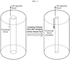
- FIG. 3 is a diagram showing the increasing normal reaction force with decreasing diameter of the winding center hole of the electrode assembly
- FIG. 4 is a diagram showing the increasing frictional force with increasing normal reaction force at the core of the electrode assembly.
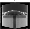
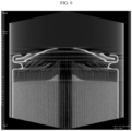
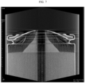
- FIGS. 5 to 7 are computed tomography (CT) images showing a change in ejection amount of the electrode assembly as a function of the diameter of the winding center hole of the electrode assembly.
- the diameter R1 of the winding center hole 10a may be equal to or larger than approximately 5.0 mm and smaller than 7.0 mm.
- the diameter R1 of the winding center hole 10a may be equal to or larger than approximately 5.0 mm and smaller than approximately 6.5 mm.
- the diameter R1 of the winding center hole 10a may be equal to or larger than approximately 6.0 mm and smaller than 6.5 mm.
- the difference (R2-R1) between the diameter R2 of the current collector hole 30a and the diameter R1 of the winding center hole 10a may be approximately 0.1 mm to 2.5 mm.
- the difference (R2-R1) between the diameter R2 of the current collector hole 30a and the diameter R1 of the winding center hole 10a may be equal to or larger than approximately 0.1 mm and smaller than 2.0 mm.
- the difference (R2-R1) between the diameter R2 of the current collector hole 30a and the diameter R1 of the winding center hole 10a may be equal to or larger than approximately 0.5 mm and smaller than 1.5 mm.
- the resistive force to the ejection force at the core of the electrode assembly 10 increases due to the increasing normal reaction force with the decreasing diameter R1 of the winding center hole 10a. This is because the frictional force between each adjacent layer of the stack including the first electrode, the second electrode and the separator increases with the increasing normal reaction force applied outwards from the core of the electrode assembly 10.
- the frictional force between each layer of the stack may act as the resistive force to the ejection force of the core of the electrode assembly 10 caused by the rise in internal pressure of the battery 1. Accordingly, when the frictional force increases, it may be possible to suppress the core ejection of the electrode assembly 10.
- the diameter R1 of the winding center hole 10a is approximately 6 mm.
- the diameter R1 of the winding center hole 10a is approximately 7 mm.
- the diameter R1 of the winding center hole 10a is approximately 8 mm.
- core ejection of the electrode assembly 10 occurs due to thermal events in the battery 1, but the ejected portion is not exposed to the outside of the battery 1.
- the core ejection length of the electrode assembly 10 is very short.
- the core ejection length of the electrode assembly 10 is very long and the electrode assembly 10 was ejected up to a location far away from the core of the electrode assembly 10.
- a value obtained by dividing the diameter R1 of the winding center hole 10a by the diameter of the electrode assembly 10 may be approximately 0.109 to 0.159.
- the value obtained by dividing the diameter R1 of the winding center hole 10a by the diameter of the electrode assembly 10 may be approximately 0.109 to 0.147.
- the value obtained by dividing the diameter R1 of the winding center hole 10a by the diameter of the electrode assembly 10 may be approximately 0.130 to 0.147.
- a value obtained by dividing the difference between the diameter R2 of the current collector hole 30a and the diameter R1 of the winding center hole 10a by the diameter of the electrode assembly 10 may be approximately 0.002 to 0.056.
- the value obtained by dividing the difference between the diameter R2 of the current collector hole 30a and the diameter R1 of the winding center hole 10a by the diameter of the electrode assembly 10 may be approximately 0.002 to 0.045.
- the value obtained by dividing the difference between the diameter R2 of the current collector hole 30a and the diameter R1 of the winding center hole 10a by the diameter of the electrode assembly 10 may be approximately 0.011 to 0.034.
- the resistive force for the suppression of core ejection of the electrode assembly 10 may be affected by a ratio of the diameter R1 of the winding center hole 10a to the total diameter of the electrode assembly 10.
- the diameter of the electrode assembly 10 of the present disclosure may be, for example, approximately 44 mm to 46 mm.
- the diameter R1 of the winding center hole 10a is too small, it may result in poor circulation of the electrolyte solution through the winding center hole 10a and/or it may be difficult to perform the process of welding the components on the opposite side to the open portion of the housing 20 through the winding center hole 10a.
- the welding is performed by laser irradiation through the winding center hole 10a, a sufficient space may be needed for stable incidence of the laser within the winding center hole 10a. Accordingly, in view of this, it is necessary to set the lower limit of the diameter R1 of the winding center hole 10a.
- the diameter R2 of the current collector hole 30a of the current collector 30 may also affect the determination of the resistive force for the suppression of core ejection of the electrode assembly 10.
- FIG. 8 is a diagram showing an upper portion structure of the battery according to an embodiment of the present disclosure.
- FIG. 9 is a top view showing the vent in the cap of the present disclosure.
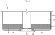
- FIG. 10 is a diagram showing a lower portion structure of the battery according to an embodiment of the present disclosure.
- the current collector 30 may be electrically connected to the housing 20.
- the current collector 30 may be, for example, electrically coupled to a beading portion extending inwards from the outer circumferential surface of the housing 20.
- the battery 1 may include a cap 40 to cover the open portion on a side of the housing 20.
- the cap 40 may be electrically insulated from the electrode assembly 10 and the housing 20, and may not be polar.
- a first insulation member G1 may be interposed between the cap 40 and the housing 20.
- the cap 40 may have a vent 40a configured to rupture when the internal pressure of the battery 1 increases.
- the vent 40a may be more vulnerable than the surrounding area.
- the vent 40a may be an area having a smaller thickness than the remaining area of the cap 40.
- the vent 40a may extend, forming a closed loop in the cap 40 as shown in FIG. 8 .
- the battery 1 of the present disclosure includes the cap 40 and the cap 40 has the vent 40a, it is more important to suppress the core ejection of the electrode assembly 10 as described above.
- core ejection is not suppressed, before gas is vented by the rupture of the vent 40a of the cap 40, a space between the cap 40 and the current collector 30 may be filled by the ejected core of the electrode assembly 10. In this case, even though the vent 40a ruptures, adequate gas venting may fail, resulting in thermal event spread.
- the battery 1 may include a first terminal T1.
- the first terminal T1 may be electrically coupled to a second uncoated portion 12 of the electrode assembly 10.
- the second uncoated portion 12 may be formed at an end portion of the second electrode.
- the second uncoated portion 12 may extend along the winding direction of the electrode assembly 10.
- the second uncoated portion 12 may be disposed on the opposite surface to the surface on which the first uncoated portion 11 is present among two surfaces of the electrode assembly 10, and for example, may extend in the downward direction of the electrode assembly 10.
- a portion of the first terminal T1 may be, for example, inserted into the housing 20 through the closed portion of the housing 20.
- the first terminal T1 may be electrically insulated from the housing 20.
- a second insulation member G2 may be interposed between the first terminal T1 and the housing 20.
- the outer surface of the closed portion of the housing 20 may act as a second terminal T2.
- the battery 1 may include a current collector (a second current collector) P to electrically connect the first terminal T1 to the electrode assembly 10.
- the current collector P may be electrically coupled to the first terminal T1.
- the current collector P and the first terminal T1 may be welded by irradiating a laser or inserting an instrument for welding through the winding center hole 10a of the electrode assembly 10 from the open portion of the housing 20.
- an insulator IS may be interposed between the current collector P and the closed portion of the housing 20.
- the insulator IS may prevent the contact between the current collector P and the housing 20 having different polarities.
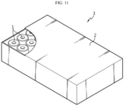
- FIG. 11 is a diagram showing the battery pack according to an embodiment of the present disclosure.
- the battery pack 3 may include at least one battery 1 of the present disclosure.
- the battery 1 may be accommodated in a pack housing 2.
- the battery pack 3 may include a component for electrical connection between the batteries 1 and/or a Battery management system (BMS) to control the charge and discharge of the battery 1.
- BMS Battery management system
- FIG. 12 is a diagram showing the vehicle according to an embodiment of the present disclosure.
- the vehicle 5 includes at least one battery pack 3.
- the vehicle 5 may be powered by the battery pack 3.
- the vehicle 5 may be, for example, a hybrid electric vehicle (HEV) or an electric vehicle (EV).
- HEV hybrid electric vehicle
- EV electric vehicle
Landscapes
- Chemical & Material Sciences (AREA)
- Chemical Kinetics & Catalysis (AREA)
- Electrochemistry (AREA)
- General Chemical & Material Sciences (AREA)
- Engineering & Computer Science (AREA)
- Manufacturing & Machinery (AREA)
- Aviation & Aerospace Engineering (AREA)
- Secondary Cells (AREA)
- Connection Of Batteries Or Terminals (AREA)
- Gas Exhaust Devices For Batteries (AREA)
Applications Claiming Priority (2)
| Application Number | Priority Date | Filing Date | Title |
|---|---|---|---|
| KR20220089125 | 2022-07-19 | ||
| PCT/KR2023/010443 WO2024019545A1 (ko) | 2022-07-19 | 2023-07-19 | 배터리, 그리고 이를 포함하는 배터리 팩 및 자동차 |
Publications (2)
| Publication Number | Publication Date |
|---|---|
| EP4496111A1 true EP4496111A1 (de) | 2025-01-22 |
| EP4496111A4 EP4496111A4 (de) | 2025-11-05 |
Family
ID=89618289
Family Applications (1)
| Application Number | Title | Priority Date | Filing Date |
|---|---|---|---|
| EP23843391.6A Pending EP4496111A4 (de) | 2022-07-19 | 2023-07-19 | Batterie und batteriepack sowie fahrzeug damit |
Country Status (6)
| Country | Link |
|---|---|
| EP (1) | EP4496111A4 (de) |
| JP (1) | JP2025526331A (de) |
| KR (1) | KR20240011645A (de) |
| CN (1) | CN118786572A (de) |
| CA (1) | CA3252770A1 (de) |
| WO (1) | WO2024019545A1 (de) |
Families Citing this family (1)
| Publication number | Priority date | Publication date | Assignee | Title |
|---|---|---|---|---|
| WO2026084500A1 (ko) * | 2024-10-17 | 2026-04-23 | 삼성에스디아이 주식회사 | 이차 전지 및 이를 포함하는 전지 팩 |
Family Cites Families (12)
| Publication number | Priority date | Publication date | Assignee | Title |
|---|---|---|---|---|
| EP0819319A4 (de) * | 1994-07-06 | 1999-03-03 | Elmer Hughett | Zelle für ein elektrisches fahrzeug |
| JP3972804B2 (ja) * | 2002-11-21 | 2007-09-05 | 松下電器産業株式会社 | アルカリ蓄電池とその製造方法 |
| JP2005150073A (ja) * | 2003-08-28 | 2005-06-09 | Matsushita Electric Ind Co Ltd | 電池およびその製造方法 |
| JP5196824B2 (ja) * | 2007-03-29 | 2013-05-15 | 三洋電機株式会社 | 円筒型電池及びその製造方法 |
| JP2008251199A (ja) * | 2007-03-29 | 2008-10-16 | Matsushita Electric Ind Co Ltd | アルカリ蓄電池用電極およびアルカリ蓄電池 |
| JP2010080294A (ja) * | 2008-09-26 | 2010-04-08 | Panasonic Corp | 二次電池 |
| KR101256743B1 (ko) * | 2009-07-17 | 2013-04-19 | 파나소닉 주식회사 | 전지케이스의 개구부가 밀봉판에 의해 밀봉된 전지 및 그 전지가 병렬 접속되어 구성된 전지 유닛 |
| JP2018055812A (ja) * | 2016-09-26 | 2018-04-05 | Fdk株式会社 | 集電リード、この集電リードを含むアルカリ二次電池の製造方法及びこの製造方法により製造したアルカリ二次電池 |
| JP7128666B2 (ja) * | 2018-06-11 | 2022-08-31 | Fdk株式会社 | 二次電池 |
| KR20220089125A (ko) | 2020-12-21 | 2022-06-28 | 강교연 | 마스크 팩 부착 가능한 마스크 |
| CA3202295A1 (en) * | 2020-12-29 | 2022-07-07 | Lg Energy Solution, Ltd. | Cylindrical battery cell, and battery pack and vehicle comprising same |
| CN216250920U (zh) * | 2021-10-20 | 2022-04-08 | 宁德时代新能源科技股份有限公司 | 电池单体、电池及用电设备 |
-
2023
- 2023-07-19 EP EP23843391.6A patent/EP4496111A4/de active Pending
- 2023-07-19 JP JP2025502676A patent/JP2025526331A/ja active Pending
- 2023-07-19 WO PCT/KR2023/010443 patent/WO2024019545A1/ko not_active Ceased
- 2023-07-19 KR KR1020230094088A patent/KR20240011645A/ko active Pending
- 2023-07-19 CN CN202380024389.0A patent/CN118786572A/zh active Pending
- 2023-07-19 CA CA3252770A patent/CA3252770A1/en active Pending
Also Published As
| Publication number | Publication date |
|---|---|
| CN118786572A (zh) | 2024-10-15 |
| WO2024019545A1 (ko) | 2024-01-25 |
| JP2025526331A (ja) | 2025-08-13 |
| CA3252770A1 (en) | 2025-03-18 |
| KR20240011645A (ko) | 2024-01-26 |
| EP4496111A4 (de) | 2025-11-05 |
Similar Documents
| Publication | Publication Date | Title |
|---|---|---|
| KR100477750B1 (ko) | 리튬 이온 전지의 전극조립체 및 이를 이용한 리튬이온 전지 | |
| EP2136429B1 (de) | Elektrodenanordnung und Lithium-Sekundärbatterie damit | |
| JP4230747B2 (ja) | サーモプロテクタが装着された二次電池 | |
| EP2924763B1 (de) | Sekundärbatterie | |
| US8927123B2 (en) | Cap assembly of cylindrical rechargeable battery and cylindrical rechargeable battery | |
| WO2011037335A2 (ko) | 이차 전지 및 그 제조 방법 | |
| KR20190033900A (ko) | 탄성 부재를 포함하는 원통형 전지셀의 캡 어셈블리 | |
| KR101975392B1 (ko) | 이차 전지 | |
| EP4496111A1 (de) | Batterie und batteriepack sowie fahrzeug damit | |
| KR101006883B1 (ko) | 전해액 흡입성 와셔를 포함하고 있는 전지 | |
| KR20070071232A (ko) | 벤트를 구비한 이차전지 및 상기 벤트 형성방법 | |
| EP4235929B1 (de) | Sekundärbatterie | |
| KR102522701B1 (ko) | 이차 전지 | |
| KR100416096B1 (ko) | 안전변 장치와 이를 채용한 이차 전지 | |
| US20230146853A1 (en) | Cylindrical secondary battery | |
| EP4231428A1 (de) | Sekundärbatterie | |
| KR20230106935A (ko) | 이차 전지 | |
| KR20220151467A (ko) | 이차 전지 | |
| KR20130019713A (ko) | 이차 전지 및 이를 제조하는 방법 | |
| KR102908460B1 (ko) | 벤트를 갖는 이차전지 | |
| KR20220033944A (ko) | 전극 조립체 및 이차 전지 | |
| KR100571233B1 (ko) | 이차 전지 | |
| EP4468430A1 (de) | Elektrodenanordnung und sekundärbatterie, batteriepack und transportmittel mit der elektrodenanordnung | |
| KR100635716B1 (ko) | 이차 전지 | |
| KR100472511B1 (ko) | 보호회로가 없는 리튬이차전지 |
Legal Events
| Date | Code | Title | Description |
|---|---|---|---|
| STAA | Information on the status of an ep patent application or granted ep patent |
Free format text: STATUS: THE INTERNATIONAL PUBLICATION HAS BEEN MADE |
|
| PUAI | Public reference made under article 153(3) epc to a published international application that has entered the european phase |
Free format text: ORIGINAL CODE: 0009012 |
|
| STAA | Information on the status of an ep patent application or granted ep patent |
Free format text: STATUS: REQUEST FOR EXAMINATION WAS MADE |
|
| 17P | Request for examination filed |
Effective date: 20241016 |
|
| AK | Designated contracting states |
Kind code of ref document: A1 Designated state(s): AL AT BE BG CH CY CZ DE DK EE ES FI FR GB GR HR HU IE IS IT LI LT LU LV MC ME MK MT NL NO PL PT RO RS SE SI SK SM TR |
|
| DAV | Request for validation of the european patent (deleted) | ||
| DAX | Request for extension of the european patent (deleted) | ||
| A4 | Supplementary search report drawn up and despatched |
Effective date: 20251007 |
|
| RIC1 | Information provided on ipc code assigned before grant |
Ipc: H01M 50/538 20210101AFI20250930BHEP Ipc: H01M 10/04 20060101ALI20250930BHEP Ipc: H01M 50/342 20210101ALI20250930BHEP Ipc: H01M 10/0587 20100101ALN20250930BHEP |