EP4496156A1 - Mehradrige elektrische verbinderanordnung und fahrzeug - Google Patents
Mehradrige elektrische verbinderanordnung und fahrzeug Download PDFInfo
- Publication number
- EP4496156A1 EP4496156A1 EP23769796.6A EP23769796A EP4496156A1 EP 4496156 A1 EP4496156 A1 EP 4496156A1 EP 23769796 A EP23769796 A EP 23769796A EP 4496156 A1 EP4496156 A1 EP 4496156A1
- Authority
- EP
- European Patent Office
- Prior art keywords
- electric connection
- connector assembly
- shape
- assembly according
- skeletons
- Prior art date
- Legal status (The legal status is an assumption and is not a legal conclusion. Google has not performed a legal analysis and makes no representation as to the accuracy of the status listed.)
- Pending
Links
Images


Classifications
-
- H—ELECTRICITY
- H01—ELECTRIC ELEMENTS
- H01R—ELECTRICALLY-CONDUCTIVE CONNECTIONS; STRUCTURAL ASSOCIATIONS OF A PLURALITY OF MUTUALLY-INSULATED ELECTRICAL CONNECTING ELEMENTS; COUPLING DEVICES; CURRENT COLLECTORS
- H01R13/00—Details of coupling devices of the kinds covered by groups H01R12/70 or H01R24/00 - H01R33/00
- H01R13/648—Protective earth or shield arrangements on coupling devices, e.g. anti-static shielding
- H01R13/658—High frequency shielding arrangements, e.g. against EMI [Electro-Magnetic Interference] or EMP [Electro-Magnetic Pulse]
- H01R13/6581—Shield structure
-
- H—ELECTRICITY
- H01—ELECTRIC ELEMENTS
- H01R—ELECTRICALLY-CONDUCTIVE CONNECTIONS; STRUCTURAL ASSOCIATIONS OF A PLURALITY OF MUTUALLY-INSULATED ELECTRICAL CONNECTING ELEMENTS; COUPLING DEVICES; CURRENT COLLECTORS
- H01R31/00—Coupling parts supported only by co-operation with counterpart
- H01R31/06—Intermediate parts for linking two coupling parts, e.g. adapter
-
- H—ELECTRICITY
- H01—ELECTRIC ELEMENTS
- H01R—ELECTRICALLY-CONDUCTIVE CONNECTIONS; STRUCTURAL ASSOCIATIONS OF A PLURALITY OF MUTUALLY-INSULATED ELECTRICAL CONNECTING ELEMENTS; COUPLING DEVICES; CURRENT COLLECTORS
- H01R25/00—Coupling parts adapted for simultaneous co-operation with two or more identical counterparts, e.g. for distributing energy to two or more circuits
- H01R25/16—Rails or bus-bars provided with a plurality of discrete connecting locations for counterparts
- H01R25/161—Details
- H01R25/162—Electrical connections between or with rails or bus-bars
-
- B—PERFORMING OPERATIONS; TRANSPORTING
- B60—VEHICLES IN GENERAL
- B60L—PROPULSION OF ELECTRICALLY-PROPELLED VEHICLES; SUPPLYING ELECTRIC POWER FOR AUXILIARY EQUIPMENT OF ELECTRICALLY-PROPELLED VEHICLES; ELECTRODYNAMIC BRAKE SYSTEMS FOR VEHICLES IN GENERAL; MAGNETIC SUSPENSION OR LEVITATION FOR VEHICLES; MONITORING OPERATING VARIABLES OF ELECTRICALLY-PROPELLED VEHICLES; ELECTRIC SAFETY DEVICES FOR ELECTRICALLY-PROPELLED VEHICLES
- B60L3/00—Electric devices on electrically-propelled vehicles for safety purposes; Monitoring operating variables, e.g. speed, deceleration or energy consumption
- B60L3/0023—Detecting, eliminating, remedying or compensating for drive train abnormalities, e.g. failures within the drive train
- B60L3/0069—Detecting, eliminating, remedying or compensating for drive train abnormalities, e.g. failures within the drive train relating to the isolation, e.g. ground fault or leak current
-
- B—PERFORMING OPERATIONS; TRANSPORTING
- B60—VEHICLES IN GENERAL
- B60L—PROPULSION OF ELECTRICALLY-PROPELLED VEHICLES; SUPPLYING ELECTRIC POWER FOR AUXILIARY EQUIPMENT OF ELECTRICALLY-PROPELLED VEHICLES; ELECTRODYNAMIC BRAKE SYSTEMS FOR VEHICLES IN GENERAL; MAGNETIC SUSPENSION OR LEVITATION FOR VEHICLES; MONITORING OPERATING VARIABLES OF ELECTRICALLY-PROPELLED VEHICLES; ELECTRIC SAFETY DEVICES FOR ELECTRICALLY-PROPELLED VEHICLES
- B60L53/00—Methods of charging batteries, specially adapted for electric vehicles; Charging stations or on-board charging equipment therefor; Exchange of energy storage elements in electric vehicles
- B60L53/10—Methods of charging batteries, specially adapted for electric vehicles; Charging stations or on-board charging equipment therefor; Exchange of energy storage elements in electric vehicles characterised by the energy transfer between the charging station and the vehicle
- B60L53/14—Conductive energy transfer
- B60L53/16—Connectors, e.g. plugs or sockets, specially adapted for charging electric vehicles
-
- H—ELECTRICITY
- H01—ELECTRIC ELEMENTS
- H01B—CABLES; CONDUCTORS; INSULATORS; SELECTION OF MATERIALS FOR THEIR CONDUCTIVE, INSULATING OR DIELECTRIC PROPERTIES
- H01B7/00—Insulated conductors or cables characterised by their form
- H01B7/17—Protection against damage caused by external factors, e.g. sheaths or armouring
-
- H—ELECTRICITY
- H01—ELECTRIC ELEMENTS
- H01B—CABLES; CONDUCTORS; INSULATORS; SELECTION OF MATERIALS FOR THEIR CONDUCTIVE, INSULATING OR DIELECTRIC PROPERTIES
- H01B7/00—Insulated conductors or cables characterised by their form
- H01B7/17—Protection against damage caused by external factors, e.g. sheaths or armouring
- H01B7/18—Protection against damage caused by wear, mechanical force or pressure; Sheaths; Armouring
-
- H—ELECTRICITY
- H01—ELECTRIC ELEMENTS
- H01B—CABLES; CONDUCTORS; INSULATORS; SELECTION OF MATERIALS FOR THEIR CONDUCTIVE, INSULATING OR DIELECTRIC PROPERTIES
- H01B7/00—Insulated conductors or cables characterised by their form
- H01B7/40—Insulated conductors or cables characterised by their form with arrangements for facilitating mounting or securing
-
- H—ELECTRICITY
- H01—ELECTRIC ELEMENTS
- H01R—ELECTRICALLY-CONDUCTIVE CONNECTIONS; STRUCTURAL ASSOCIATIONS OF A PLURALITY OF MUTUALLY-INSULATED ELECTRICAL CONNECTING ELEMENTS; COUPLING DEVICES; CURRENT COLLECTORS
- H01R13/00—Details of coupling devices of the kinds covered by groups H01R12/70 or H01R24/00 - H01R33/00
- H01R13/62—Means for facilitating engagement or disengagement of coupling parts or for holding them in engagement
- H01R13/621—Bolt, set screw or screw clamp
- H01R13/6215—Bolt, set screw or screw clamp using one or more bolts
-
- H—ELECTRICITY
- H01—ELECTRIC ELEMENTS
- H01R—ELECTRICALLY-CONDUCTIVE CONNECTIONS; STRUCTURAL ASSOCIATIONS OF A PLURALITY OF MUTUALLY-INSULATED ELECTRICAL CONNECTING ELEMENTS; COUPLING DEVICES; CURRENT COLLECTORS
- H01R13/00—Details of coupling devices of the kinds covered by groups H01R12/70 or H01R24/00 - H01R33/00
- H01R13/73—Means for mounting coupling parts to apparatus or structures, e.g. to a wall
-
- H—ELECTRICITY
- H01—ELECTRIC ELEMENTS
- H01R—ELECTRICALLY-CONDUCTIVE CONNECTIONS; STRUCTURAL ASSOCIATIONS OF A PLURALITY OF MUTUALLY-INSULATED ELECTRICAL CONNECTING ELEMENTS; COUPLING DEVICES; CURRENT COLLECTORS
- H01R4/00—Electrically-conductive connections between two or more conductive members in direct contact, i.e. touching one another; Means for effecting or maintaining such contact; Electrically-conductive connections having two or more spaced connecting locations for conductors and using contact members penetrating insulation
- H01R4/28—Clamped connections, spring connections
- H01R4/30—Clamped connections, spring connections utilising a screw or nut clamping member
- H01R4/34—Conductive members located under head of screw
-
- H—ELECTRICITY
- H01—ELECTRIC ELEMENTS
- H01R—ELECTRICALLY-CONDUCTIVE CONNECTIONS; STRUCTURAL ASSOCIATIONS OF A PLURALITY OF MUTUALLY-INSULATED ELECTRICAL CONNECTING ELEMENTS; COUPLING DEVICES; CURRENT COLLECTORS
- H01R4/00—Electrically-conductive connections between two or more conductive members in direct contact, i.e. touching one another; Means for effecting or maintaining such contact; Electrically-conductive connections having two or more spaced connecting locations for conductors and using contact members penetrating insulation
- H01R4/58—Electrically-conductive connections between two or more conductive members in direct contact, i.e. touching one another; Means for effecting or maintaining such contact; Electrically-conductive connections having two or more spaced connecting locations for conductors and using contact members penetrating insulation characterised by the form or material of the contacting members
- H01R4/62—Connections between conductors of different materials; Connections between or with aluminium or steel-core aluminium conductors
-
- B—PERFORMING OPERATIONS; TRANSPORTING
- B60—VEHICLES IN GENERAL
- B60L—PROPULSION OF ELECTRICALLY-PROPELLED VEHICLES; SUPPLYING ELECTRIC POWER FOR AUXILIARY EQUIPMENT OF ELECTRICALLY-PROPELLED VEHICLES; ELECTRODYNAMIC BRAKE SYSTEMS FOR VEHICLES IN GENERAL; MAGNETIC SUSPENSION OR LEVITATION FOR VEHICLES; MONITORING OPERATING VARIABLES OF ELECTRICALLY-PROPELLED VEHICLES; ELECTRIC SAFETY DEVICES FOR ELECTRICALLY-PROPELLED VEHICLES
- B60L2270/00—Problem solutions or means not otherwise provided for
- B60L2270/10—Emission reduction
- B60L2270/14—Emission reduction of noise
- B60L2270/145—Structure borne vibrations
-
- B—PERFORMING OPERATIONS; TRANSPORTING
- B60—VEHICLES IN GENERAL
- B60L—PROPULSION OF ELECTRICALLY-PROPELLED VEHICLES; SUPPLYING ELECTRIC POWER FOR AUXILIARY EQUIPMENT OF ELECTRICALLY-PROPELLED VEHICLES; ELECTRODYNAMIC BRAKE SYSTEMS FOR VEHICLES IN GENERAL; MAGNETIC SUSPENSION OR LEVITATION FOR VEHICLES; MONITORING OPERATING VARIABLES OF ELECTRICALLY-PROPELLED VEHICLES; ELECTRIC SAFETY DEVICES FOR ELECTRICALLY-PROPELLED VEHICLES
- B60L53/00—Methods of charging batteries, specially adapted for electric vehicles; Charging stations or on-board charging equipment therefor; Exchange of energy storage elements in electric vehicles
- B60L53/10—Methods of charging batteries, specially adapted for electric vehicles; Charging stations or on-board charging equipment therefor; Exchange of energy storage elements in electric vehicles characterised by the energy transfer between the charging station and the vehicle
- B60L53/14—Conductive energy transfer
- B60L53/18—Cables specially adapted for charging electric vehicles
-
- H—ELECTRICITY
- H01—ELECTRIC ELEMENTS
- H01R—ELECTRICALLY-CONDUCTIVE CONNECTIONS; STRUCTURAL ASSOCIATIONS OF A PLURALITY OF MUTUALLY-INSULATED ELECTRICAL CONNECTING ELEMENTS; COUPLING DEVICES; CURRENT COLLECTORS
- H01R11/00—Individual connecting elements providing two or more spaced connecting locations for conductive members which are, or may be, thereby interconnected, e.g. end pieces for wires or cables supported by the wire or cable and having means for facilitating electrical connection to some other wire, terminal, or conductive member, blocks of binding posts
- H01R11/11—End pieces or tapping pieces for wires, supported by the wire and for facilitating electrical connection to some other wire, terminal or conductive member
- H01R11/26—End pieces terminating in a screw clamp, screw or nut
-
- H—ELECTRICITY
- H01—ELECTRIC ELEMENTS
- H01R—ELECTRICALLY-CONDUCTIVE CONNECTIONS; STRUCTURAL ASSOCIATIONS OF A PLURALITY OF MUTUALLY-INSULATED ELECTRICAL CONNECTING ELEMENTS; COUPLING DEVICES; CURRENT COLLECTORS
- H01R2103/00—Two poles
-
- H—ELECTRICITY
- H01—ELECTRIC ELEMENTS
- H01R—ELECTRICALLY-CONDUCTIVE CONNECTIONS; STRUCTURAL ASSOCIATIONS OF A PLURALITY OF MUTUALLY-INSULATED ELECTRICAL CONNECTING ELEMENTS; COUPLING DEVICES; CURRENT COLLECTORS
- H01R2201/00—Connectors or connections adapted for particular applications
- H01R2201/26—Connectors or connections adapted for particular applications for vehicles
-
- H—ELECTRICITY
- H01—ELECTRIC ELEMENTS
- H01R—ELECTRICALLY-CONDUCTIVE CONNECTIONS; STRUCTURAL ASSOCIATIONS OF A PLURALITY OF MUTUALLY-INSULATED ELECTRICAL CONNECTING ELEMENTS; COUPLING DEVICES; CURRENT COLLECTORS
- H01R24/00—Two-part coupling devices, or either of their cooperating parts, characterised by their overall structure
- H01R24/28—Coupling parts carrying pins, blades or analogous contacts and secured only to wire or cable
-
- H—ELECTRICITY
- H01—ELECTRIC ELEMENTS
- H01R—ELECTRICALLY-CONDUCTIVE CONNECTIONS; STRUCTURAL ASSOCIATIONS OF A PLURALITY OF MUTUALLY-INSULATED ELECTRICAL CONNECTING ELEMENTS; COUPLING DEVICES; CURRENT COLLECTORS
- H01R4/00—Electrically-conductive connections between two or more conductive members in direct contact, i.e. touching one another; Means for effecting or maintaining such contact; Electrically-conductive connections having two or more spaced connecting locations for conductors and using contact members penetrating insulation
- H01R4/28—Clamped connections, spring connections
- H01R4/30—Clamped connections, spring connections utilising a screw or nut clamping member
- H01R4/302—Clamped connections, spring connections utilising a screw or nut clamping member having means for preventing loosening of screw or nut, e.g. vibration-proof connection
Definitions
- the present disclosure relates to the field of electric energy transmission, and particular to a multi-core electric connector assembly and a vehicle.
- the connector assembly on the new energy automotive needs to meet the requirement for driving the high-power motor, so that the transmitted current is relatively large, and the diameter of the high-voltage cable on the connector assembly is also increased.
- the high-voltage cable on the most connector assembly is multi-core copper cable and is large in weight and high in price, which are barriers that limit the popularization of the new energy automotive.
- the multi-core cable is soft and can be conveniently processed and wired, due to the large cable diameter, the weight is large. In a traveling process of the vehicle, the cable frequently rub against a vehicle shell, resulting in damage of the insulating protective layer of the cable, which causes high-voltage discharge, damaging the vehicle in minor cases, and causing serious traffic accidents in serious cases.
- One purpose of the present disclosure is to provide a new technical solution of a multi-core electric connector assembly.
- a multi-core electric connector assembly includes at least two electric connection skeletons and connectors arranged at two ends of the electric connection skeleton, and the connector includes an outer shell and a connection terminal, at least one end of the electric connection skeleton is connected to the connection terminal, the connection terminal is arranged on the connector, and insulating protective layers are arranged between the electric connection skeletons and on a periphery of the electric connection skeletons.
- a ratio of a distance between the electric connection skeletons to the thickness or diameter of the electric connection skeleton is 2% to 86%.
- the electric connection skeleton includes at least one bent portion.
- the connector and the electric connection skeleton are integrally formed.
- At least a portion of the electric connection skeleton is flexible.
- the cross sectional area of the electric connection skeleton is 3.5 mm 2 to 240 mm 2 .
- a cross section of the electric connection skeleton is in one or more selected from a circular shape, an oval shape, a rectangular shape, a polygonal shape, an A shape, a B shape, a D shape, an M shape, an N shape, an O shape, an S shape, an E shape, an F shape, an H shape, a K shape, an L shape, a T shape, a U shape, a V shape, a W shape, an X shape, a Y shape, a Z shape, a P shape, a semi-arc shape, an arc shape and a wavy shape.
- a shape of a cross section of the electric connection skeleton is in a polygonal shape, and all corners of the polygonal shape are chamfered or rounded.
- the electric connection skeleton is a rigid body, and the tensile strength of the electric connection skeleton is higher than 75 MPa.
- a material of the connection terminal contains copper or a copper alloy
- a material of the electric connection skeleton contains aluminum or an aluminum alloy
- the electric connection skeleton is electrically connected to the connection terminal in a welding or crimping manner.
- the welding manner includes one or more selected from a resistance welding manner, a friction welding manner, an ultrasonic welding manner, an arc welding manner, a laser welding manner, an electron beam welding manner, a pressure diffusion welding manner, a magnetic induction welding manner and a crimping manner.
- connection manner for the connection terminal and the electric connection skeleton includes one or more selected from a threaded connection manner, a snap-fitting manner and a splicing manner.
- connection terminal is provided with a through hole or a threaded hole
- electric connection skeleton is provided with a threaded hole or a through hole
- the through hole and/or the threaded hole are connected by means of bolt structure.
- connection terminal is arranged on the connector by means of a fixing member.
- the bolt structure is provided with an anti-loosening member, the anti-loosening member is sleeved or snap-fitted between the bolt structure and the fixing member, and the anti-loosening member prevents the bolt structure from loosening.
- the fixing member is arranged on an inner wall of the outer shell, an inner wall of the fixing member is provided with a groove or a boss, a periphery of an end portion of the connection terminal is provided with a boss or a groove, and the boss is snap-fitted with the groove.
- the electric connection skeletons are arranged inside the insulating protective layer in a up-down stacked manner.
- the electric connection skeletons are mirrorings of each other.
- an overlapping area of the electric connection skeletons in a stacking direction are 13% to 100%.
- the electric connection skeletons are arranged inside the insulating protective layer in parallel in an axial direction.
- the electric connection skeletons are arranged inside the insulating protective layer in a mutually twisted manner in an axial direction.
- a ratio of the twist length of mutual twisting of the electric connection skeletons to the maximum outer diameter of the electric connection skeleton is less than or equal to 15.
- a minimum thickness of the insulating protective layer between the stacked electric connection skeletons is 0.1 cm to 27 cm.
- a minimum thickness of the insulating protective layer between the stacked electric connection skeletons is 0.15 cm to 7 cm.
- the insulating protective layers are arranged between the electric connection skeletons and on the periphery of the electric connection skeletons in an injection molding manner.
- a periphery of the insulating protective layer is sleeved with a shielding layer
- the shielding layer is one of or a combination of a metal with a shielding effect and a composite material of the metal, and a plastic with a shielding effect or a rubber with a shielding effect or a textile with a shielding effect.
- the outer shell is internally provided with an inner shielding shell with a shielding effect
- the inner shielding shell is electrically connected to the shielding layer
- an inner wall of the inner shielding shell is provided with the fixing member.
- an impedance between the inner shielding shell and the shielding layer is less than 80 m ⁇ .
- a transfer impedance of the inner shielding shell is less than 100 m ⁇ .
- a transfer impedance of the shielding layer is less than 100 m ⁇ .
- a periphery of the shielding layer is further sleeved with a sheath layer.
- a part of an inner surface of the outer shell is connected to a part of an outer surface of the sheath layer.
- one of the connectors is a charging socket.
- a vehicle is provided and includes the multi-core electric connector assembly.
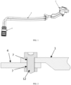
- a multi-core electric connector assembly includes at least two electric connection skeletons 1 and connectors 2 arranged at two ends of the electric connection skeleton 1, and the connector 2 includes an outer shell 3 and a connection terminal 4, at least one end of the electric connection skeleton 1 is connected to the connection terminal 4, the connection terminal 4 is arranged on the connector 2, and insulating protective layers 6 are arranged between the electric connection skeletons 1 and on a periphery of the electric connection skeletons.
- connection terminal 4 is fixed to the connector 2, separation of the connection terminal 4 and the connector 2 caused by vibration of the electric connection skeleton 1 in a traveling process of a vehicle can be avoided, thereby prolonging the service life of the multi-core electric connector assembly; and due to the fact that the at least two electric connection skeletons 1 are included and can be respectively connected to a positive electrode end and a negative electrode end of a charging power source or a vehicle-mounted battery, so that a vehicle assembling procedure is simplified, the production cost is saved, and wiring in the vehicle is more concise.
- the electric connection skeletons are up-down stacked, and currents in the two electric connection skeletons are the same in magnitude and opposite in direction, so that induced magnetic fields are the same in intensity and opposite in direction, the induced magnetic fields generated by the two electric connection skeletons cancel each other, the effect of shielding the electromagnetic interference is achieved, the anti-electromagnetic interference performance is improved, the shielding layer can be omitted, the production process is simplified, raw materials are saved, the production cost is reduced, and the market competitiveness is improved.
- a ratio of a distance between the electric connection skeletons 1 to the thickness or diameter of the electric connection skeleton 1 is 2% to 86%.
- the electric connection skeletons 1 in each sample are cut into two sections, in one section, the insulating protective layer 6 between the two electric connection skeletons 1 is dissected to observe whether there is a hole formed by insufficient injection molding, it is unqualified when there is a hole, and if there are the hole it is recorded in Table 1.
- different high voltages are applied between the two electric connection skeletons 1, so as to test the voltage resistance of the insulating protective layer 6 between the two electric connection skeletons 1.
- the breakdown voltage of the insulating protective layer lower than 2.1 KV is unqualified and is recorded in Table 1.
- Table 1 Influence of ratio of distance between two electric connection skeletons 1 to thickness of electric connection skeleton 1 on cancellation of magnetic fields in case of an overlapping area of two stacked electric connection skeletons 1 being 100% Ratio of distance between two electric connection skeletons 1 to thickness of electric connection skeleton 1 (%) Magnetic field cancellation percent Whether there is a hole Average value of breakdown voltage (KV) First sample Second sample Third sample Fourth sample Fifth sample 100 0.0% 0.0% 0.0% 0.0% 0.0% 0.0% 0.0% No 4.73 95 11.2% 11.3% 11.4% 10.8% 11.0% No 4.59 90 16.2% 21.6% 26.1% 25.9% 24.4% No 4.35 86 30.4% 30.9% 30.3% 30.6% 30.3% No 4.31 75 41.6% 42.1% 44.1% 41.7% 44.3% No 4.29 70 51.4% 51.3% 51.9% 53.8% 52.9% No 3.95 64 58.3% 53.1% 57.9% 59.2% 61.4% No 3.82 59 70.4% 61.4% 66.1% 68.3%
- the overlapping area means the percent of the overlapping area of the two electric connection skeletons 1 in the stacking direction to the area of one electric connection skeleton 1.
- the ratio of the distance between the two electric connection skeletons 1 to the thickness of the electric connection skeleton 1 is less than 2%, the distance between the two electric connection skeletons 1 is too short, and the insulating protective layer 6 between the two electric connection skeletons 1 cannot be injection-molded into a narrow gap, so that there is a hole in the insulating protective layer 6 between the two electric connection skeletons 1.
- the breakdown voltage of the insulating protective layer 6 between the two electric connection skeletons 1 be lower than 2.1 KV, so that it is unqualified when the ratio of the distance between the two electric connection skeletons 1 to the thickness of the electric connection skeleton 1 is less than 2%, and when the ratio of the distance between the two electric connection skeletons 1 to the thickness of the electric connection skeleton 1 is greater than 86%, the magnetic field cancellation percent less than 30% is also unqualified. Therefore, the inventor chooses that the ratio of the distance between the two electric connection skeletons 1 to the thickness of the electric connection skeleton 1 is 2% to 86%.
- the electric connection skeleton 1 includes at least one bent portion.
- the bent portion can be arranged on electric connection skeleton 1 according to requirements, so that there is the bent portion in the position where the direction of the electric connection skeleton 1 needs to be changed in a wiring process on the vehicle, wiring by an operator is facilitated, processing hours of the vehicle are shortened, thereby reducing the production cost of the vehicle, and increasing the market competitiveness.
- the connector 2 and the electric connection skeleton 1 are integrally formed.
- the connector 2 and the electric connection skeleton 1 are integrally formed, so that the connection stability of the electric connection skeleton 1 and the connector 2 can be improved, and thereby prolonging the service life of the electric connector assembly.
- At least a portion of the electric connection skeleton 1 is flexible.
- the portion of electric connection skeleton 1 that needs to be bent is set to be flexible, so that the electric connector assembly is easier to mount when assembled on the vehicle, the operation is facilitated, and the production hours are shortened.
- connection skeleton 1 is set to be flexible (that is, the outer shell), so that it can be fixed to a vehicle body conveniently when assembled on the vehicle body, abnormal sounds generated between the outer shell 3 and a vehicle shell or the connector 2 connected to two ends due to vibration can be reduced, and breakage at the connection position with the connection terminal 4 can be avoided. Meanwhile, short-circuit phenomena and burning of the vehicle in serious cases, caused by the electric connection of the outer shell 3 with the vehicle body due to damage to the insulating protective layer led by frequent friction of a part of the outer shell 3 with the vehicle body are also avoided.
- the cross sectional area of the electric connection skeleton 1 is 3.5 mm 2 to 240 mm 2 .
- the cross sectional area of the electric connection skeleton 1 determines the current that can be conducted by the electric connection skeleton 1, generally, the electric connection skeleton 1 for achieving signal conduction has a smaller current, and the sectional area of the electric connection skeleton 1 is also small, for example, the minimum sectional area of the electric connection skeleton 1 for transmitting signals can be 3.5 mm 2 ; and the electric connection skeleton 1 for achieving power source conduction has a lager current, the cross sectional area of the electric connection skeleton 1 is also large, for example, for an automotive storage battery wire harness, the maximum sectional area of the electric connection skeleton 1 can reach 240 mm 2 .
- a cross section of the electric connection skeleton 1 is in one or more selected from a circular shape, an oval shape, a rectangular shape, a polygonal shape, an A shape, a B shape, a D shape, an M shape, an N shape, an O shape, an S shape, an E shape, an F shape, an H shape, a K shape, an L shape, a T shape, a U shape, a V shape, a W shape, an X shape, a Y shape, a Z shape, a P shape, a semi-arc shape, an arc shape and a wavy shape.
- the shape of the cross section of the electric connection skeleton 1 can be designed specifically according to a wiring space in the vehicle, thereby facilitating wiring in the vehicle and assembly of the vehicle by the operator.
- a shape of a cross section of the electric connection skeleton is in a polygonal shape, and all corners of the polygonal shape are chamfered or rounded.
- all the corners of electric connection skeleton 1 with the cross section in the polygonal shape are chamfered or rounded, so that the connection between the electric connection skeleton 1 and the connection terminal can be facilitated, when being welded or crimped, the electric connection skeleton 1 is connected to the connection terminal more firmly, the contact area is larger, and the conduction current is better; heating and even burning accidents caused by excessively large resistance caused by excessively a small contact area between the electric connection skeleton 1 and the connection terminal during connection are avoided; and casualties and the property loss caused by scratching of the insulating protective layer 6 by an edge formed by two adjacent sides of the polygonal shape during use can also be avoided.
- the electric connection skeleton 1 is a rigid body, and the tensile strength of the electric connection skeleton 1 is higher than 75 MPa.
- the rigid body refers to an object with the shape and size unchanged and relative positions of various points inside unchanged during motion and after being stressed.
- An absolute rigid body does not actually exist and is only an ideal model, because any object will be deformed to a certain extent after being stressed. If the deformation degree is very low relative to geometric dimensions of the object, the deformation can be omitted when the motion of the object is researched. Therefore, during use of the electric connection skeleton 1 made of the rigid body material, the produced deformation amount is very little and can be omitted, and as the tensile strength of the rigid body increases, the deformation amount is reduced.
- the inventor selects electric connection skeleton 1 samples with the same dimensions and different tensile strength to test the torque of the electric connection skeletons 1 when being bent and whether the electric connection skeletons 1 have abnormal sounds in the vibration process.
- a test method for the tensile value of the electric connection skeleton 1 is as follows: using a universal tensile test machine, respectively fixing the two ends of the electric connection skeleton 1 to tensile jigs of the universal tensile test machine, performing stretching at a speed of 50 mm/min, and recording the tensile value when finally being pulled apart.
- the tensile value greater than 1600 N is a qualified value.
- a test method for the torque of the electric connection skeletons 1 are as follows: using a torque tester, and when the electric connection skeleton 1 is bent by 90° at the same radius and the same speed, testing the torque value of deformation of the electric connection skeleton 1 in the bending process.
- the torque value less than 60 N ⁇ m is an exemplary value.
- Whether the electric connection skeleton 1 has the abnormal sounds is tested with such a method that the electric connection skeleton 1 samples with the same dimensions and different tensile strength and the connectors 2 with the same dimensions are selected, assembled together and fixed on a vibration test platform, and in a vibration test process, whether the electric connection skeletons 1 have the abnormal sounds is observed.
- the tensile strength of the electric connection skeleton 1 is less than or equal to 75 Mpa, the electric connection skeleton 1 can produce abnormal sounds in the vibration test process. Therefore, for the inventor, the tensile strength of the electric connection skeleton 1 is exemplarily higher than 75 MPa.
- the tensile strength of the electric connection skeleton 1 is higher than 480 Mpa, the torque value of the electric connection skeleton 1 when being bent by 90° is greater than 60 N ⁇ m, and then the electric connection skeleton 1 is not bent easily. Therefore, for the inventor, the tensile strength of the electric connection skeleton 1 is further exemplarily higher than 75 MPa and lower than or equal to 480 MPa.
- the electric connection skeletons are configured as the rigid bodies, in the traveling process of the vehicle, the electric connection skeletons cannot shake with the traveling of the vehicle, the friction with the vehicle shell is reduced, high-voltage discharge caused by damage of the insulating protective layers is avoided, traffic accidents are reduced, and the service life of the connector assembly is prolonged.
- the electric connection skeletons are the rigid bodies, and the electric connection skeletons and the connection terminals are fixedly mounted on the vehicle body, so that the relative movement between the electric connection skeletons and the connection terminals is effectively restrained, the abnormal sounds generated in the traveling process of the vehicle is avoided, the quality of the vehicle is improved, and the comfort during riding is improved.
- a material of the connection terminal 4 contains copper or a copper alloy
- a material of the electric connection skeleton 1 contains aluminum or an aluminum alloy
- the electric connection skeleton 1 is electrically connected to the connection terminal 4 in a welding or crimping manner.
- the welding manner includes one or more selected from a resistance welding manner, a friction welding manner, an ultrasonic welding manner, an arc welding manner, a laser welding manner, an electron beam welding manner, a pressure diffusion welding manner, a magnetic induction welding manner, and a crimping manner.
- the electric connection skeleton 1 is connected to the connection terminal 4 in the welding manner.
- the used welding manner includes one or more selected from a resistance welding manner, a friction welding manner, an ultrasonic welding manner, an arc welding manner, a laser welding manner, an electron beam welding manner, a pressure diffusion welding manner and a magnetic induction welding manner.
- the contact position of the connection terminal and the electric connection skeleton is fused and connected by means of concentrated heat or pressure, stable connection is achieved by means of the welding manner, connection of dissimilar materials can be achieved, and the electric conduction effect is better due to fusion of the contact position.
- the resistance welding manner refers to a method of using a large current to pass through a contact point between an electrode and a workpiece and generating heat by the contact resistance to achieve welding.
- the friction welding manner refers to a method of using heat produced by rubbing of a contact face of the workpiece as a heat source and enabling the workpiece to be subjected to plastic deformation under the action of pressure so as to perform welding.
- the ultrasonic welding manner means that high-frequency vibration waves are transmitted to surfaces of two objects to be welded and the surfaces of the two objects rub against each other, under the condition of pressurization, to achieve fusion between two molecular layers.
- the arc welding manner means that an electric arc serves as a heat source, by means of the physical phenomenon of air discharge, electric energy is converted into heat energy and mechanical energy required by welding, so as to achieve the purpose of connecting metals, and main methods include a shielded metal arc welding method, a submerged arc welding method and a gas shielded welding method.
- the laser welding manner is an efficient precision welding method using a laser beam with a high energy density as a heat source.
- the friction welding manner refers to a method of using heat produced by rubbing of a contact face of the workpiece as a heat source and enabling the workpiece to be subjected to plastic deformation under the action of pressure so as to perform welding.
- the electron beam welding manner means an accelerated and focused electron beam bombards a welding face placed in the vacuum or non-vacuum so that a welded workpiece is melted for welding.
- the pressure welding manner is a method for applying pressure to a welded workpiece so that connection faces make close contact to generate certain plastic deformation to complete welding.
- the magnetic induction welding manner means two welded workpieces produce an instantaneous high-speed collision under the action of a strong pulsed magnetic field, surface layers of materials are subjected to high pressure waves, and thus atoms of the two materials meet within the atomic spacing, thereby forming stable metallurgical bonding on an interface. It is one kind of solid-state cold welding, by which conducting metals with similar or dissimilar properties can be welded together.
- crimping is a production technology for stamping the electric connection skeleton 1 and the connection terminal 4 into a whole by means of a crimping machine after assembly.
- the crimping has an advantage of mass production, and a large number of products with stable quality can be quickly manufactured by means of an automatic crimping machine.
- a connection manner for the connection terminal 4 and the electric connection skeleton 1 includes one or more selected from a threaded connection manner, a snap-fitting manner and a splicing manner.
- connection terminal 4 and the electric connection skeleton 1 are connected through threaded connection, snap-fitting and splicing, and during later use and maintenance, a customer can select to replace damaged parts according to specific conditions, thereby reducing the maintenance cost of the customer.
- the splicing manner means that the connection terminal 4 and the electric connection skeleton 1 are respectively provided with a groove and a corresponding protrusion, and assembly is performed by means of joggle joint or splicing of the groove and the protrusion so as to connect the two parts together.
- the splicing manner has advantages of stable connection and detachability.
- the threaded connection manner refers to screwed joint and detachable connection in which the connection terminal 4 and the electric connection skeleton 1 are connected into a whole by means of threaded structures matched with each other.
- connection terminal 4 and the electric connection skeleton 1 are respectively provided with a clamping jaw or a corresponding clamping groove, and assembly is performed by means of the clamping groove and the clamping jaw to connect the two parts together.
- the snap-fitting manner has advantages of quick connection and detachability.
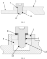
- connection terminal 4 is provided with a through hole 7 or a threaded hole 13
- the electric connection skeleton 1 is provided with a threaded hole 13 or a through hole 7, and the through hole 7 and/or the threaded hole 13 are connected by means of bolt structure 12.
- connection terminal 4 and the electric connection skeleton 1 are connected in the threaded connection, snap-fitting or splicing manner, so that the connection terminal 4 and the electric connection skeleton 1 are detachably connected, and when a certain part is damaged, the damaged part is convenient to maintain and replace.
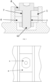
- the through holes 7 are formed in connection positions of connection terminal 4 and the electric connection skeleton 1, and the bolt structure 12 passes through the two through holes to be connected to a nut; and as shown in FIG. 3 and FIG. 4 , the bolt structure 12 sequentially passes through the through hole 7 and the threaded hole 13, and an external thread at a screw of the bolt structure 12 is connected to the thread of the threaded hole 13.
- connection terminal 4 is arranged on the connector 2 by means of a fixing member 5.
- the fixing member 5 is arranged on the connector 2, the connection terminal 4 are fixed by means of the fixing member 5, and the position of the fixing member 5 can be reasonably set according to space of the connector 2, so that the connection terminal 4 are directly connected to the connector 2, the more flexible effect is achieved, and the relative positions can be determined according to actual requirements.
- the bolt structure 12 is provided with an anti-loosening member 8, the anti-loosening member 8 is sleeved or snap-fitted between the bolt structure 12 and the fixing member 5, and the anti-loosening member 8 prevents the bolt structure 12 from loosening.
- the anti-loosening member 8 is arranged, so that the condition that the multi-core electric connector assembly cannot achieve electric conduction due to falling off as a result of off as a result of vibration causing loosening between the connection terminal 4 and the fixing member 5 is avoided in the traveling process of the vehicle.
- anti-loosening member 8 can be set as a compression spring, the compression spring is arranged between the head of the bolt structure 12 and the fixing member 5, and after the bolt structure 12 is tightened, a certain acting force is provided for the head of the bolt structure 12 by means of the compression spring, so as to prevent the bolt structure 12 from being loosened.
- anti-loosening member 8 is a cuboid, the middle of which is provided with a through hole for accommodating the head of the bolt structure 12, and a periphery of the cuboid is snap-fitted in a clamping groove for fixing the connection terminal 4 and the electric connection skeleton 1 in the connector 2, thereby preventing the bolt structure 12 from being loosened.
- the fixing member 5 is arranged on an inner wall of the outer shell 3, an inner wall of the fixing member 5 is provided with a groove or a boss, a periphery of an end portion of the connection terminal 4 is provided with a boss or a groove, and the boss is snap-fitted with the groove.
- the fixing member 5 and the connection terminal 4 are connected in the snap-fitting manner, so that when one of the connection terminal 4 or outer shell 3 is damaged, the damaged part can be timely replaced, the maintenance cost is reduced, and the operation is convenient and quick.
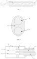
- the electric connection skeletons 1 are arranged inside the insulating protective layer 6 in an up-down stacked manner. It is ensured that the electric connection skeletons 1 arranged in the up-down stacked manner are insulated from each other.
- connection skeletons 1 are mirrorings of each other.
- the electric connection skeletons are the mirrorings of each other, and currents in the two electric connection skeletons 1 are the same in magnitude and opposite in direction, so that induced magnetic fields are the same in intensity and opposite in direction, the induced magnetic fields generated by the two electric connection skeletons 1 cancel each other, the effect of shielding the electromagnetic interference is achieved, the anti-electromagnetic interference performance is improved, the shielding layer can be omitted, the production process is simplified, raw materials are saved, the production cost is reduced, and the market competitiveness is improved.
- an overlapping area of the electric connection skeletons 1 in a stacking direction are 13% to 100%.
- Table 3 shows the influence of the overlapping area of the two electric connection skeletons 1 in the stacking direction on cancellation of the magnetic fields, and the magnetic field cancellation percent greater than 30% is a qualified value.
- Table 3 Influence of overlapping area of stacked electric connection skeletons 1 on cancellation of magnetic fields in case of distance between two electric connection skeletons 1 being 7 cm Overlapping area of stacked electric energy transmission guide rails
- A Magnetic field cancellation percent
- Second sample Third sample
- Fourth sample Fifth sample 0% 0.0% 0.0% 0.0% 0.0% 0.0% 0.0% 0.0% 0.0% 10% 12.1% 12.2% 11.8% 12.0% 11.9% 13% 30.1% 30.8% 31.1% 31.3% 32.1% 25% 33.1% 33.8% 34.1% 34.7% 35.1% 40% 40.1% 42.8% 43.1% 43.9% 44.6% 50% 45.8% 43.6% 46.9% 48.3% 43.6% 70% 49.9% 50.3% 50.8% 51.2% 49.8% 90% 60.2% 60.7% 60.1% 60.6% 61.1% 95% 80.1% 80.1% 80.9% 80.8% 80.8% 98% 97.3% 97.8% 97.2% 97.4% 97.1% 100% 99.8% 100.0% 100.0% 100.0% 99.9%
- the electric connection skeletons 1 are arranged inside the insulating protective layer 6 in parallel in an axial direction.
- the electric connection skeletons 1 are arranged inside the insulating protective layer 6 in parallel in the axial direction, burning accidents caused by short circuiting between the two electric connection skeletons 1 can be prevented, and the electric connection skeletons 1 in an electrified state are isolated from the outside, thereby preventing people from getting an electric shock and injured.
- the electric connection skeletons 1 are arranged inside the insulating protective layer 6 in a mutually twisted manner in an axial direction.
- the two electric connection skeletons are arranged inside the insulating protective layer 6 in the twisted manner, burning accidents caused by short circuiting between the two electric connection skeletons 1 can be prevented, and the electric connection skeletons 1 in an electrified state are isolated from the outside, thereby preventing people from getting an electric shock and injured.
- the outer diameter of a cable can be reduced, thereby facilitating storage and transportation of the electric connection skeletons during production, and saving the assembly space when assembing to the vehicle.
- a ratio of the twist length of mutual twisting of the electric connection skeletons 1 to the maximum outer diameter of the electric connection skeleton 1 is less than or equal to 15.
- Table 4 shows the influence of the ratio of the twist length of mutual twisting of the electric connection skeletons 1 to the maximum outer diameter of the electric connection skeleton 1 on cancellation of the magnetic fields, and the magnetic field cancellation percent greater than 30% is a qualified value.
- the inventor chooses that the ratio of the twist length of mutual twisting of the electric connection skeletons 1 to the maximum outer diameter of the electric connection skeleton 1 is less than or equal to 15.
- a minimum thickness of the insulating protective layer 6 between the stacked electric connection skeletons 1 is 0.1 cm to 27 cm.
- a minimum thickness of the insulating protective layer 6 between the stacked electric connection skeletons 1 is 0.15 cm to 7 cm.
- the cross sections of the two electric connection skeletons 1 being in the rectangular shape is taken as an example for illustration, the width directions of the two electric connection skeletons 1 are parallel to each other, the electric connection skeletons 1 are mirrorings of each other, the thickness of the insulating protective layer 6 between the two electric connection skeletons 1 is H, and the stacking direction of the two electric connection skeletons 1 is a yp-down direction.
- Table 5 shows the influence of the thickness H of the insulating protective layer 6 between the two electric connection skeletons 1 on cancellation of the magnetic fields, and the magnetic field cancellation percent greater than 30% is a qualified value.
- the electric connection skeletons 1 in each sample are cut into two sections, in one section, the insulating protective layer 6 between the two electric connection skeletons 1 is dissected to observe whether there is a hole formed by insufficient injection molding, it is unqualified when there is a hole, and if there are the hole it is recorded in Table 5.
- different high voltages are applied between the two electric connection skeletons 1, so as to test the voltage resistance of the insulating protective layer 6 between the two electric connection skeletons 1.
- the breakdown voltage of the insulating protective layer lower than 2.1 KV is unqualified and is recorded in Table 5.
- Table 5 Influence of thickness H of insulating protective layer 6 between two electric connection skeletons 1 on cancellation of magnetic fields in case of the overlapping area of two stacked electric connection skeletons 1 being 100% Thickness of insulating protective layer 6 between two electric connection skeletons 1 (H) Magnetic field cancellation percent Whether there is a hole Average value of breakdown voltage (KV) First sample Second sample Third sample Fourth sample Fifth sample 30cm 0.0% 0.0% 0.0% 0.0% 0.0% 0.0% 0.0% No 4.63 29cm 11.0% 11.1% 11.3% 10.9% 11.0% No 4.51 28cm 15.2% 20.7% 25.2% 25.4% 24.6% No 4.39 27cm 30.5% 30.3% 30.2% 30.7% 30.3% No 4.27 25cm 40.6% 42.1% 45.1% 41.7% 40.3% No 4.16 23cm 51.4% 50.2% 52.2% 53.3% 51.2% No 3.94 21cm 59.3% 50.1% 58.6% 59.3% 61.2% No 3.82 19cm 70.4% 60.4% 65
- the overlapping area means the percent of the overlapping area of the two electric connection skeletons 1 in the stacking direction to the area of one electric connection skeleton 1.
- the thickness H of the insulating protective layer 6 between the two electric connection skeletons 1 is further set to be less than or equal to 7 cm.
- the thickness of the insulating protective layer 6 between the two electric connection skeletons 1 is less than or equal to 0.1 cm, the distance between the two electric connection skeletons 1 is too short, and the insulating protective layer 6 between the two electric connection skeletons 1 cannot be injection-molded into a narrow gap, so that there is a hole in the insulating protective layer 6 between the two electric connection skeletons 1. It also makes the breakdown voltage of the insulating protective layer 6 between the two electric connection skeletons 1 be lower than 2.1 KV, so that it is unqualified when the thickness of the insulating protective layer 6 between the two electric connection skeletons 1 is less than 0.1 cm.
- the thickness of the insulating protective layer 6 between the two electric connection skeletons 1 is increased to 0.15 cm, the breakdown voltage can be remarkably increased to 2.35 KV, during actual production, the thickness of 0.15 cm can improve the smoothness of the inj ection-molding operation, and the hole can be almost eliminated. Therefore, for the inventor, the thickness of the insulating protective layer 6 is further exemplarily 0.15 cm to 7 cm.
- the insulating protective layers 6 are arranged between the electric connection skeletons 1 and on the periphery of the electric connection skeletons in an injection molding manner.
- the insulating protective layers 6 are arranged between the twisted electric connection skeletons 1 and on the periphery of the electric connection skeletons, burning accidents caused by short circuiting between the two electric connection skeletons 1 can be prevented, and the electric connection skeletons 1 in an electrified state are isolated from the outside, thereby preventing people from getting an electric shock and injured.
- a periphery of the insulating protective layer 6 is sleeved with a shielding layer 9, and the shielding layer 9 is one of or a combination of a metal with a shielding effect and a composite material of the metal, and a plastic with a shielding effect or a rubber with a shielding effect or a textile with a shielding effect.
- electromagnetic waves generated by the electric connection skeletons 1 during use can be shielded, thereby preventing the electric connection skeletons 1 from interfering with other instruments and devices during use.
- the shielding layer 9 can reduce the interference of electromagnetic radiation generated by the electric connection skeletons 1 on other electric devices in the vehicle, and the shielding layer 9 is made of a conductor and need to be grounded, so that the insulating protective layer is arranged between the shielding layer 9 and the electric connection skeleton 1 to prevent them from making contact with each other.
- the outer shell 3 is internally provided with an inner shielding shell 10 with a shielding effect
- the inner shielding shell 10 is electrically connected to the shielding layer 9
- an inner wall of the inner shielding shell 10 is provided with the fixing member 5.
- electromagnetic radiation or electromagnetic wave interference of the connection terminal 4 in an electrified state can be shielded, thereby preventing the condition that electric devices cannot operate normally due to electromagnetic interference.
- impedance between the inner shielding shell 10 and the shielding layer 9 is less than 80 m ⁇ .
- the inventor uses the electric connection skeletons 1 with the same specification, connectors 2 with the same specification, inner shielding shells 10 with the same specification and connection terminals 4 with the same specification, and different impedance between the shielding layers 9 and the inner shielding shells 10 to produce a series of samples, the shielding effects are tested respectively, and experimental results are as shown in Table 6 below.
- the shielding property value greater than 40 dB is an ideal value.
- the shielding property value is less than 40 dB and does not meet the requirement of the ideal value; and when the impedance value between the shielding layer 9 and the inner shielding shell 10 is less than 80 m ⁇ , the shielding property value meets the requirement of the ideal value and tends to be better. Therefore, the inventor sets the impedance between the shielding layer 9 and the inner shielding shell 10 to be less than 80 m ⁇ .
- transfer impedance of the inner shielding shell 10 is less than 100 m ⁇ .
- the inventor uses the electric connection skeletons 1 with the same specification, connectors 2 with the same specification and connection terminals 4 with the same specification and the inner shielding shells 10 with the different transfer impedance values to produce a series of samples, the shielding effects are tested respectively, and experimental results are as shown in Table 7 below.
- the shielding property value greater than 40 dB is an ideal value.
- Table 7 Influence of transfer impedance of inner shielding shell 10 on shielding property Test parameter Transfer impedance of inner shielding shell 10 (m ⁇ ) 20 30 40 50 60 70 80 90 100 110 120 Shielding property value (dB) 79 76 73 67 64 58 54 45 41 29 27
- transfer impedance of the shielding layer 9 is less than 100 m ⁇ .
- the inventor uses the electric connection skeletons 1 with the same specification, connectors 2 with the same specification and connection terminals 4 with the same specification and the inner shielding shells 10 with the different transfer impedance values to produce a series of samples, the shielding effects are tested respectively, and experimental results are as shown in Table 8 below.
- the shielding property value greater than 40 dB is an ideal value.
- Table 8 Influence of transfer impedance of inner shielding shell 10 on shielding property Test parameter Transfer impedance of inner shielding shell 10 (m ⁇ ) 20 30 40 50 60 70 80 90 100 110 120 Shielding property value (dB) 80 78 74 66 63 61 55 46 40 28 25
- a periphery of the shielding layer 9 is further sleeved with a sheath layer 11.
- the shielding layer 9 can be protected during use of the electric connection skeleton 1, so that the condition that the shielding properties of the shielding layer 9 is affected due to damage of the shielding layer 9 due to external forces is avoided; meanwhile, the vortex current in the shielding layer 9 is prevented from being conducted by means of the outside, thereby achieving the effect of isolating the shielding layer 9 from the outside, thereby prolonging the service life of the multi-core electric connector assembly.
- a part of an inner surface of the outer shell 3 is connected to a part of an outer surface of the sheath layer 11.
- the insulation arrangement between the connector and the electric connection skeleton 1 can be ensured, thereby preventing casualties due to electric shocks.
- one of the connectors 2 is a charging socket.
- the charging socket is connected to a charging gun, and the connector 2 at the other end is a high-voltage connector and is connected to the rechargeable batteries, thereby achieving the purpose of charging the rechargeable batteries.
- a vehicle in the present disclosure includes the multi-core electric connector assembly.
Landscapes
- Engineering & Computer Science (AREA)
- Power Engineering (AREA)
- Transportation (AREA)
- Mechanical Engineering (AREA)
- Life Sciences & Earth Sciences (AREA)
- Sustainable Development (AREA)
- Sustainable Energy (AREA)
- Connector Housings Or Holding Contact Members (AREA)
- Electric Propulsion And Braking For Vehicles (AREA)
- Details Of Connecting Devices For Male And Female Coupling (AREA)
Applications Claiming Priority (2)
| Application Number | Priority Date | Filing Date | Title |
|---|---|---|---|
| CN202210250053.3A CN114709685A (zh) | 2022-03-14 | 2022-03-14 | 一种多芯电连接器总成和车辆 |
| PCT/CN2023/081407 WO2023174294A1 (zh) | 2022-03-14 | 2023-03-14 | 一种多芯电连接器总成和车辆 |
Publications (2)
| Publication Number | Publication Date |
|---|---|
| EP4496156A1 true EP4496156A1 (de) | 2025-01-22 |
| EP4496156A4 EP4496156A4 (de) | 2025-08-13 |
Family
ID=82169597
Family Applications (1)
| Application Number | Title | Priority Date | Filing Date |
|---|---|---|---|
| EP23769796.6A Pending EP4496156A4 (de) | 2022-03-14 | 2023-03-14 | Mehradrige elektrische verbinderanordnung und fahrzeug |
Country Status (5)
| Country | Link |
|---|---|
| US (1) | US20250192493A1 (de) |
| EP (1) | EP4496156A4 (de) |
| CN (1) | CN114709685A (de) |
| MX (1) | MX2024011366A (de) |
| WO (1) | WO2023174294A1 (de) |
Families Citing this family (2)
| Publication number | Priority date | Publication date | Assignee | Title |
|---|---|---|---|---|
| CN114709685A (zh) * | 2022-03-14 | 2022-07-05 | 吉林省中赢高科技有限公司 | 一种多芯电连接器总成和车辆 |
| CN116632595A (zh) * | 2022-12-24 | 2023-08-22 | 长春捷翼汽车科技股份有限公司 | 一种连接器组件 |
Family Cites Families (18)
| Publication number | Priority date | Publication date | Assignee | Title |
|---|---|---|---|---|
| JP5263141B2 (ja) * | 2009-12-18 | 2013-08-14 | 日立電線株式会社 | 車両用接続構造 |
| US9166312B2 (en) * | 2014-03-14 | 2015-10-20 | Raycap, S.A. | Terminal block assemblies and printed circuit board assemblies including same |
| CN105490109A (zh) * | 2015-11-27 | 2016-04-13 | 贵州航天电器股份有限公司 | 一种电连接器的防转锁紧机构 |
| JP6122094B1 (ja) * | 2015-12-25 | 2017-04-26 | 株式会社フジクラ | 充電コネクタ組立体の製造方法 |
| DE112016006665T5 (de) * | 2016-03-31 | 2018-12-20 | Autonetworks Technologies, Ltd. | Kommunikationskabel |
| JP6747212B2 (ja) * | 2016-09-26 | 2020-08-26 | 株式会社オートネットワーク技術研究所 | フラット電線の固定構造 |
| CN206471646U (zh) * | 2017-01-18 | 2017-09-05 | 凡甲电子(苏州)有限公司 | 线缆连接器组件 |
| DE102017112947A1 (de) * | 2017-06-13 | 2018-12-13 | Te Connectivity Germany Gmbh | Elektrischer Hochstromverbinder sowie Verfahren zum Herstellen eines elektrischen Hochstromverbinders |
| DE102018221611B4 (de) * | 2017-12-25 | 2022-12-22 | Yazaki Corporation | Kabelbaumeinheit, Stromspeichereinheit und Kabelbaum |
| EP4121322A1 (de) * | 2020-03-16 | 2023-01-25 | Tesla, Inc. | Abgeschirmte hochleistungssammelschiene zum laden und verteilen von strom in einem elektrofahrzeug |
| CN212304133U (zh) * | 2020-05-13 | 2021-01-05 | 台州市路桥豪达汽车电器有限公司 | 新能源汽车电机高压线束总成 |
| CN113471781B (zh) * | 2021-07-30 | 2025-09-09 | 吉林省中赢高科技有限公司 | 一种线束模块及组合式线束 |
| CN113745881A (zh) * | 2021-08-06 | 2021-12-03 | 长春捷翼汽车零部件有限公司 | 充电座及汽车 |
| CN113708159A (zh) * | 2021-08-21 | 2021-11-26 | 长春捷翼汽车零部件有限公司 | 一种屏蔽线缆连接结构 |
| CN113602111A (zh) * | 2021-09-02 | 2021-11-05 | 长春捷翼汽车零部件有限公司 | 一种用于车辆的电能传输系统、充电装置和电动车辆 |
| CN113922137A (zh) * | 2021-10-01 | 2022-01-11 | 长春捷翼汽车零部件有限公司 | 一种带屏蔽的连接机构、电能传输装置及机动车辆 |
| CN217823616U (zh) * | 2022-03-14 | 2022-11-15 | 吉林省中赢高科技有限公司 | 一种多芯电连接器总成和车辆 |
| CN114709685A (zh) * | 2022-03-14 | 2022-07-05 | 吉林省中赢高科技有限公司 | 一种多芯电连接器总成和车辆 |
-
2022
- 2022-03-14 CN CN202210250053.3A patent/CN114709685A/zh active Pending
-
2023
- 2023-03-14 WO PCT/CN2023/081407 patent/WO2023174294A1/zh not_active Ceased
- 2023-03-14 EP EP23769796.6A patent/EP4496156A4/de active Pending
- 2023-03-14 US US18/847,204 patent/US20250192493A1/en active Pending
-
2024
- 2024-09-13 MX MX2024011366A patent/MX2024011366A/es unknown
Also Published As
| Publication number | Publication date |
|---|---|
| US20250192493A1 (en) | 2025-06-12 |
| WO2023174294A1 (zh) | 2023-09-21 |
| CN114709685A (zh) | 2022-07-05 |
| EP4496156A4 (de) | 2025-08-13 |
| MX2024011366A (es) | 2024-12-06 |
Similar Documents
| Publication | Publication Date | Title |
|---|---|---|
| EP4398270A1 (de) | Elektrisches energieübertragungssystem für ein fahrzeug sowie ladevorrichtung und elektrofahrzeug | |
| CN217823618U (zh) | 一种电能传输总成及车辆 | |
| EP4496156A1 (de) | Mehradrige elektrische verbinderanordnung und fahrzeug | |
| KR101421859B1 (ko) | 전극 단자 및 전극 단자의 제조 방법 | |
| EP4496142A1 (de) | Elektrische energieübertragungsverbindungsvorrichtung und fahrzeug | |
| EP4496152A1 (de) | Elektrische energieübertragungsanordnung und fahrzeug | |
| US20200350099A1 (en) | Electroconductive path and wire harness | |
| EP4496153A1 (de) | Elektrische energieübertragungsanordnung und fahrzeug | |
| EP4459814A1 (de) | Einfach austauschbare ladesteckdose und fahrzeug | |
| EP4307504A1 (de) | Kabelanordnung und herstellungsverfahren dafür | |
| KR20100132481A (ko) | 호스 조립체 | |
| EP4495956A1 (de) | Elektrische energieübertragungsanordnung und fahrzeug | |
| EP4495957A1 (de) | Elektrisches energieübertragungssystem und kraftfahrzeug | |
| EP4496144A1 (de) | Verbinderanordnung und verarbeitungsverfahren | |
| CN217823616U (zh) | 一种多芯电连接器总成和车辆 | |
| CN217823621U (zh) | 一种连接器总成及一种车辆 | |
| EP4494918A1 (de) | Flexible verbindungsstruktur eines verbinders und fahrzeug | |
| CN217823495U (zh) | 一种连接器柔性连接结构及一种车辆 | |
| EP4496141A1 (de) | Neuartige verbinderanordnung auf abschirmungsmaterialbasis und fahrzeug | |
| EP4131671B1 (de) | Profilverbinder | |
| CN217215265U (zh) | 一种可释放应力的线缆密封结构及一种车辆 | |
| EP4266327A1 (de) | Elektrisches hochspannungskabel mit gemischten leitern | |
| EP4379971B1 (de) | Kabelbaummodul und kombinierter kabelbaum | |
| CN217822167U (zh) | 一种电能传输系统及一种汽车 | |
| JP2024093184A (ja) | 端子、及び、端子付き電線 |
Legal Events
| Date | Code | Title | Description |
|---|---|---|---|
| STAA | Information on the status of an ep patent application or granted ep patent |
Free format text: STATUS: THE INTERNATIONAL PUBLICATION HAS BEEN MADE |
|
| PUAI | Public reference made under article 153(3) epc to a published international application that has entered the european phase |
Free format text: ORIGINAL CODE: 0009012 |
|
| STAA | Information on the status of an ep patent application or granted ep patent |
Free format text: STATUS: REQUEST FOR EXAMINATION WAS MADE |
|
| 17P | Request for examination filed |
Effective date: 20241011 |
|
| AK | Designated contracting states |
Kind code of ref document: A1 Designated state(s): AL AT BE BG CH CY CZ DE DK EE ES FI FR GB GR HR HU IE IS IT LI LT LU LV MC ME MK MT NL NO PL PT RO RS SE SI SK SM TR |
|
| DAV | Request for validation of the european patent (deleted) | ||
| DAX | Request for extension of the european patent (deleted) | ||
| P01 | Opt-out of the competence of the unified patent court (upc) registered |
Free format text: CASE NUMBER: APP_22622/2025 Effective date: 20250513 |
|
| A4 | Supplementary search report drawn up and despatched |
Effective date: 20250711 |
|
| RIC1 | Information provided on ipc code assigned before grant |
Ipc: H01R 31/06 20060101AFI20250707BHEP Ipc: H01R 13/73 20060101ALI20250707BHEP Ipc: H01R 13/621 20060101ALI20250707BHEP Ipc: H01B 7/40 20060101ALI20250707BHEP Ipc: H01B 7/18 20060101ALI20250707BHEP Ipc: H01B 7/17 20060101ALI20250707BHEP Ipc: B60L 53/16 20190101ALI20250707BHEP Ipc: B60L 53/18 20190101ALI20250707BHEP Ipc: H01B 7/00 20060101ALI20250707BHEP Ipc: H01B 7/02 20060101ALI20250707BHEP Ipc: H01B 9/00 20060101ALI20250707BHEP Ipc: H01R 4/00 20060101ALI20250707BHEP Ipc: H01R 11/00 20060101ALI20250707BHEP Ipc: H01R 4/34 20060101ALI20250707BHEP Ipc: H01R 13/6581 20110101ALI20250707BHEP Ipc: H01R 25/16 20060101ALI20250707BHEP |
|
| STAA | Information on the status of an ep patent application or granted ep patent |
Free format text: STATUS: EXAMINATION IS IN PROGRESS |
|
| 17Q | First examination report despatched |
Effective date: 20260324 |