EP4496174A2 - Chargeur de batterie - Google Patents
Chargeur de batterie Download PDFInfo
- Publication number
- EP4496174A2 EP4496174A2 EP24188192.9A EP24188192A EP4496174A2 EP 4496174 A2 EP4496174 A2 EP 4496174A2 EP 24188192 A EP24188192 A EP 24188192A EP 4496174 A2 EP4496174 A2 EP 4496174A2
- Authority
- EP
- European Patent Office
- Prior art keywords
- battery
- power
- charging device
- battery charging
- control
- Prior art date
- Legal status (The legal status is an assumption and is not a legal conclusion. Google has not performed a legal analysis and makes no representation as to the accuracy of the status listed.)
- Pending
Links
Images

Classifications
-
- H—ELECTRICITY
- H02—GENERATION; CONVERSION OR DISTRIBUTION OF ELECTRIC POWER
- H02J—ELECTRIC POWER NETWORKS; CIRCUIT ARRANGEMENTS OR SYSTEMS FOR SUPPLYING OR DISTRIBUTING ELECTRIC POWER; SYSTEMS FOR STORING ELECTRIC ENERGY
- H02J7/00—Circuit arrangements for charging or discharging batteries or for supplying loads from batteries
- H02J7/485—Circuit arrangements for charging or discharging batteries or for supplying loads from batteries with provisions for charging different types of batteries
-
- H—ELECTRICITY
- H02—GENERATION; CONVERSION OR DISTRIBUTION OF ELECTRIC POWER
- H02J—ELECTRIC POWER NETWORKS; CIRCUIT ARRANGEMENTS OR SYSTEMS FOR SUPPLYING OR DISTRIBUTING ELECTRIC POWER; SYSTEMS FOR STORING ELECTRIC ENERGY
- H02J7/00—Circuit arrangements for charging or discharging batteries or for supplying loads from batteries
- H02J7/40—Circuit arrangements for charging or discharging batteries or for supplying loads from batteries characterised by the exchange of charge or discharge related data
- H02J7/44—Circuit arrangements for charging or discharging batteries or for supplying loads from batteries characterised by the exchange of charge or discharge related data between battery management systems and power sources
-
- H—ELECTRICITY
- H02—GENERATION; CONVERSION OR DISTRIBUTION OF ELECTRIC POWER
- H02J—ELECTRIC POWER NETWORKS; CIRCUIT ARRANGEMENTS OR SYSTEMS FOR SUPPLYING OR DISTRIBUTING ELECTRIC POWER; SYSTEMS FOR STORING ELECTRIC ENERGY
- H02J7/00—Circuit arrangements for charging or discharging batteries or for supplying loads from batteries
- H02J7/90—Regulation of charging or discharging current or voltage
- H02J7/971—Regulation of charging or discharging current or voltage the charge cycle being controlled or terminated in response to non-electric parameters
- H02J7/975—Regulation of charging or discharging current or voltage the charge cycle being controlled or terminated in response to non-electric parameters in response to temperature
- H02J7/977—Regulation of charging or discharging current or voltage the charge cycle being controlled or terminated in response to non-electric parameters in response to temperature of the battery
Definitions
- the invention relates to a battery charging device for charging one or more connected batteries of a specific battery type, wherein the battery charging device comprises a power part and a control part.
- the power part serves to provide the charging power to be delivered to the connected one or more batteries.
- the control part serves to control the charging method for charging the connected one or more batteries, adapted to the battery-specific properties of the connected one or more batteries.
- the WO 2009/007157 A1 a battery charging device with a charging current generating device and a charging current controlling device.
- the charging current controlling device is configured to recognize a first battery type of a first battery pack that has lithium-ion cells based on a transition metal oxide and to recognize a second battery type of a second battery pack that has lithium-ion cells based on a metal phosphate, while the charging current generating device is configured to apply a first charging method that is suitable for the first battery pack and to apply a second charging method that is suitable for the second battery pack.
- the publication DE 10 2013 201 221 A1 discloses an energy storage system with a control device for charging a first lead battery and for charging a second lithium-ion battery.
- the control device comprises a management master device, which is used to monitor the lithium-ion battery.
- the management master device uses models and algorithms to determine variables such as the charge level, aging level and performance of the battery based on measured values and data that are transmitted from the slave electronics of the battery to the management master device.
- the management master device then transmits the data to a higher-level evaluation and control unit.
- the management master device can either be an integral part of the battery, or in the case of a lithium-ion battery that is more complex to monitor, the management master device can be integrated into the control device.
- the development of a battery charger with a specific (mechanical and electrical) interface for charging one or more specific batteries and with the respective models and algorithms for parameterizing and controlling the respective charging process depending on the battery requires a great deal of effort in validating and verifying the battery charger based on a charger specification in order to ensure its safe use by the user.
- the disadvantage here is that this is necessary every time the manufacturer or supplier of battery chargers changes, but also every time a new battery charger is developed. Battery charging device including the creation of new software for the charging process.
- one object of the invention is to reduce the associated effort of validating and verifying the battery charging device.
- a battery charging device having the features of claim 1 and a battery charging system comprising a battery charging device and at least one or more connectable batteries according to claim 9.
- battery refers to any type of chargeable and rechargeable battery, i.e., among other things, individual cells as well as cells in a pack or several battery packs in a pack.
- the shape and arrangement of the cells in a pack has no significant impact on the subject matter of the invention, i.e., for example, this also includes so-called cylindrical cells, prismatic cells or pouch cells.
- all conceivable specific types of battery cells are also included in the term battery, i.e., for example, lithium-ion battery cells based on a metal phosphate or lithium-ion battery cells based on a transition metal oxide, NiCd cells or NiMH cells.
- a battery of a specific battery type refers to a battery that requires a charging method adapted to its battery-specific properties or parts.
- batteries of a specific battery type within the meaning of the present application are to be assigned to the same specific battery type if they are charged using the same battery-specific charging method.
- the battery charging device differs from known devices in that it has a modular structure, wherein the power module, which comprises at least one power part, is independent of the Control module, which comprises at least one control part, is provided in such a way that the validation and verification of the power module can be carried out independently of the validation and verification of the control module. In this way, it is possible to develop, validate and verify the power module and the control module and consequently also the at least one power part and the at least one control part independently of one another.
- the at least one power unit serves to supply one or more connected, i.e. electrically connected, batteries of a specific type with a charging power of a power source or current source of the battery charging device, i.e. with charging current or charging voltage, according to a specific charging method.
- the power unit can control the current source, which in turn is electrically connected to the batteries to be charged.
- the power unit can determine the charging current and/or the charging voltage (ACTUAL) delivered to the battery(ies) and compare it with a TARGET value specified according to the charging method.
- the current source can be regulated accordingly by the power unit.
- a master-slave topology is also present here, as in solutions known from the prior art, in which the battery charging device forms the master in relation to the at least one battery to be charged and connected as the slave.
- the at least one power part can become the slave unit as an independent unit separated from the at least one control part, which can be controlled by the at least one control part, while the at least one control part in this case becomes the master unit for the at least one power part connected to it.
- the at least one control part serves to determine battery-specific data of the battery(ies) to be charged, for example via a data interface. Based on this, the control part can determine whether the connected batteries correspond to the battery-specific type of the battery charging device, and in this way ensure that only the batteries to which the battery-specific charging method of the battery charging device is applicable are charged.
- the control part includes the control of the specific parts of a battery of a specific battery type.
- the control part can also include different controls for batteries of different specific battery types, for example a first control for batteries of a first specific battery type and a second control for batteries of a second specific battery type.
- the control part can also be suitable for more than two different battery types.
- the control part can in particular be scaled to a large number of battery types.
- the control unit controls the power unit in a similar way to a controllable power supply with a voltage and current regulation using control signals that are transmitted via the Communication interface from the control module to the line module.
- control module and the power module are provided in a single microcontroller, in which the modular division of the charge controller and the application controller as well as the communication interface are implemented in the form of installed software.
- control module preferably comprises a first microcontroller and the power module comprises a second microcontroller, which are designed separately from one another (i.e. physically separated) and communicate with one another via a digital communication interface (hereinafter also referred to as "Com. Interface").
- control module is designed to exchange battery-specific data with one or more connected batteries via a data interface.
- the power module can be configured to receive sensor data from a temperature sensor for detecting the battery temperature of one or more connected batteries via a data interface.
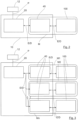
- control module can have a number of n control parts (where n denotes an integer), with each control part being assigned at least one battery of a battery type specific to the control part that can be connected to the battery charging device.
- the power module comprises a single power section, wherein each of the n control sections is connected to the power section via a communication interface.
- One power unit serves as an energy supplier for the (master) control units 1 to n.
- the respective master control unit regulates the energy supply for the respective connected battery in order to charge it safely.
- the respective master control unit receives the parameters required for safe and efficient charging from the at least one connected battery.
- the respective parameters and later algorithms have already been validated and verified by the manufacturer. According to a conceivable further development of the invention, the parameters and algorithms can be read out by the user, for example via wireless communication (WLAN, Bluetooth (LE), narrowband, NFC), adapted to his needs and, if necessary, also set within defined limits or overwritten with other validated and verified parameters and algorithms.
- the at least one control part can read and process manufacturer-specific parameters of the connected battery, which in turn serve as the basis for controlling the power part (as a slave).
- manufacturer-specific parameters of the connected battery which in turn serve as the basis for controlling the power part (as a slave).
- different control modules for charging different batteries (batteries of a different specific battery type) and from different manufacturers can be configured into a single battery charging device, all of which access, for example, only a single power part of the battery charging device.
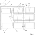
- the power module comprises at least two power parts, wherein at least a first of the n control parts is connected to the first power part via a first communication interface, and wherein at least one further of the n control parts is connected to the further power part via a further communication interface.
- each of the n control units can be assigned to its own power unit.
- a cascadable module solution is created that enables faster charging of the connected batteries, since sequential charging of the batteries via a single power unit is not required.
- n control units can be assigned to their own power unit and other control units can access one or more power units together.
- the provision of power or charging energy from a direct current and/or alternating current source can be carried out sequentially or in parallel with one or more power modules and one or more power units until the respective connected batteries are fully charged.
- Cascaded (master) control units can be prioritized for this purpose.
- time slot Another option is to activate a so-called "time slot” algorithm.
- This time-based algorithm means that each battery to be charged that is connected to the battery charger is charged sequentially for a parameterizable period of time with up to a maximum available charging power. The next (master) control unit is then activated and is given the opportunity to charge the battery connected to it.
- the aim of this algorithm is for all connected batteries to be fully charged or to a specified value (e.g. 80%) as simultaneously as possible.
- the battery charging device an emergency shutdown which is designed to receive sensor data from a temperature sensor for detecting the battery temperature of one or more connected batteries via a data interface and to deactivate the power supply from the power source of the battery charging device when a predetermined threshold value is exceeded.
- the respective master control part 40 receives the parameters required for safe and efficient charging from the at least one connected battery 100.
- the respective parameters and later algorithms are already validated and verified by the manufacturer. According to a conceivable further development of the invention (not shown), the parameters and algorithms can be read out by the user, for example via wireless communication (WLAN, Bluetooth (LE), narrowband, NFC), adapted to his needs, and if necessary also set within defined limits or overwritten with other validated and verified parameters and algorithms.
Landscapes
- Engineering & Computer Science (AREA)
- Power Engineering (AREA)
- Charge And Discharge Circuits For Batteries Or The Like (AREA)
Applications Claiming Priority (1)
| Application Number | Priority Date | Filing Date | Title |
|---|---|---|---|
| DE102023119421.6A DE102023119421A1 (de) | 2022-07-21 | 2023-07-21 | Batterieladevorrichtung |
Publications (2)
| Publication Number | Publication Date |
|---|---|
| EP4496174A2 true EP4496174A2 (fr) | 2025-01-22 |
| EP4496174A3 EP4496174A3 (fr) | 2025-03-05 |
Family
ID=91946493
Family Applications (1)
| Application Number | Title | Priority Date | Filing Date |
|---|---|---|---|
| EP24188192.9A Pending EP4496174A3 (fr) | 2023-07-21 | 2024-07-12 | Chargeur de batterie |
Country Status (1)
| Country | Link |
|---|---|
| EP (1) | EP4496174A3 (fr) |
Citations (3)
| Publication number | Priority date | Publication date | Assignee | Title |
|---|---|---|---|---|
| WO2009007157A1 (fr) | 2007-07-06 | 2009-01-15 | Robert Bosch Gmbh | Dispositif de chargement de batteries |
| DE102013201221A1 (de) | 2013-01-25 | 2014-07-31 | Robert Bosch Gmbh | Ansteuervorrichtung für ein elektrisches Energiespeichersystem |
| CN111740466A (zh) | 2020-07-08 | 2020-10-02 | 东莞市乐丰电器科技有限公司 | 一种智能识别锂电池种类和串数的充电器及充电方法 |
Family Cites Families (7)
| Publication number | Priority date | Publication date | Assignee | Title |
|---|---|---|---|---|
| US20020101218A1 (en) * | 1984-05-21 | 2002-08-01 | Intermec Ip Corp | Battery pack having memory |
| US20080238357A1 (en) * | 2007-03-26 | 2008-10-02 | Bourilkov Jordan T | Ultra fast battery charger with battery sensing |
| EP2014423A3 (fr) * | 2007-06-14 | 2014-01-22 | Black & Decker Inc. | Système d'identification de bloc-batterie |
| US9692089B2 (en) * | 2010-12-30 | 2017-06-27 | Duracell U.S. Operations, Inc. | Single wire battery pack temperature and identification method |
| US8525483B2 (en) * | 2011-04-20 | 2013-09-03 | Carl Lee Danner | Control of battery charging power |
| US20130002199A1 (en) * | 2011-06-29 | 2013-01-03 | Ran Hu | Charging of Li-ion Batteries |
| US20140081940A1 (en) * | 2012-09-20 | 2014-03-20 | Delta-Q Technologies Corp. | System and Method for Data Transfer with a Battery Charger |
-
2024
- 2024-07-12 EP EP24188192.9A patent/EP4496174A3/fr active Pending
Patent Citations (3)
| Publication number | Priority date | Publication date | Assignee | Title |
|---|---|---|---|---|
| WO2009007157A1 (fr) | 2007-07-06 | 2009-01-15 | Robert Bosch Gmbh | Dispositif de chargement de batteries |
| DE102013201221A1 (de) | 2013-01-25 | 2014-07-31 | Robert Bosch Gmbh | Ansteuervorrichtung für ein elektrisches Energiespeichersystem |
| CN111740466A (zh) | 2020-07-08 | 2020-10-02 | 东莞市乐丰电器科技有限公司 | 一种智能识别锂电池种类和串数的充电器及充电方法 |
Also Published As
| Publication number | Publication date |
|---|---|
| EP4496174A3 (fr) | 2025-03-05 |
Similar Documents
| Publication | Publication Date | Title |
|---|---|---|
| DE102023119421A1 (de) | Batterieladevorrichtung | |
| EP3209518B1 (fr) | Procédé permettant de faire fonctionner un dispositif d'accumulation d'énergie dans un véhicule automobile et véhicule automobile | |
| EP2803110B1 (fr) | Système de batterie pour véhicule à moteur | |
| DE112014007057T5 (de) | Energiespeichersystem basiert auf Batteriepacks | |
| DE102013200763A1 (de) | System und verfahren für das fahrzeugenergiemanagement | |
| EP2355229A1 (fr) | Système de batterie à courant élevé et procédé de commande d'un système de batterie à courant élevé | |
| EP2245718A1 (fr) | Système de gestion de batterie | |
| DE19503917A1 (de) | Elektronische Batterieüberwachungseinrichtung | |
| DE102014105653A1 (de) | Batterieüberwachungsvorrichtung und Batterieeinheit | |
| DE102017123071B4 (de) | Versorgung von Niedervolt-Bordnetzen von Fahrzeugen mit elektrischem Antrieb | |
| DE102014219889A1 (de) | Fahrzeug und Verfahren zum Steuern einer Batterie in einem Fahrzeug | |
| DE102018214658A1 (de) | Fehlererfassungsvorrichtung | |
| DE102020215648B4 (de) | Verfahren zum Steuern eines Stromversorgungssystems für ein Mild-Hybrid-Elektrofahrzeug | |
| DE112012006861B4 (de) | Batterieladesystem und Verfahren zum kabellosen Laden einer Batterie | |
| DE102012015522A1 (de) | Batterielager- und -logistiksystem | |
| DE202016105619U1 (de) | Intelligenter Akkumulator | |
| EP4496174A2 (fr) | Chargeur de batterie | |
| DE102022116264A1 (de) | Verfahren zum parallelen elektrischen Verbinden eines Satzes von Batteriepaketen, ein elektronisches Steuergerät, ein Computerprogramm, ein computerlesbares Speichermedium, ein Batteriesystem und ein Kraftfahrzeug | |
| DE102011115825A1 (de) | Verfahren und Vorrichtung zur Zustandsüberwachung einer Anzahl von Batterien | |
| EP3534453B1 (fr) | Bloc d'accumulateur pour un appareil électrique, chargeur pour un bloc d'accumulateur et procédé de fonctionnement d'un bloc d'accumulateur | |
| DE102012209885A1 (de) | Vorrichtung und Verfahren zum Betreiben eines elektrischen Energiespeichers | |
| EP2803109B1 (fr) | Système de batterie pour véhicule à moteur | |
| EP3901870B1 (fr) | Gestion liée au projet des blocs d'accumulateur | |
| EP3670246A1 (fr) | Dispositif de charge pour chariots de manutention | |
| EP3217509B1 (fr) | Dépôt provisoire pour unités de batterie |
Legal Events
| Date | Code | Title | Description |
|---|---|---|---|
| PUAI | Public reference made under article 153(3) epc to a published international application that has entered the european phase |
Free format text: ORIGINAL CODE: 0009012 |
|
| STAA | Information on the status of an ep patent application or granted ep patent |
Free format text: STATUS: THE APPLICATION HAS BEEN PUBLISHED |
|
| AK | Designated contracting states |
Kind code of ref document: A2 Designated state(s): AL AT BE BG CH CY CZ DE DK EE ES FI FR GB GR HR HU IE IS IT LI LT LU LV MC ME MK MT NL NO PL PT RO RS SE SI SK SM TR |
|
| PUAL | Search report despatched |
Free format text: ORIGINAL CODE: 0009013 |
|
| AK | Designated contracting states |
Kind code of ref document: A3 Designated state(s): AL AT BE BG CH CY CZ DE DK EE ES FI FR GB GR HR HU IE IS IT LI LT LU LV MC ME MK MT NL NO PL PT RO RS SE SI SK SM TR |
|
| RIC1 | Information provided on ipc code assigned before grant |
Ipc: H02J 7/00 20060101AFI20250124BHEP |
|
| STAA | Information on the status of an ep patent application or granted ep patent |
Free format text: STATUS: REQUEST FOR EXAMINATION WAS MADE |
|
| 17P | Request for examination filed |
Effective date: 20250725 |