EP4496190A1 - Dispositif de commande de rotation avant et arrière - Google Patents
Dispositif de commande de rotation avant et arrière Download PDFInfo
- Publication number
- EP4496190A1 EP4496190A1 EP23213037.7A EP23213037A EP4496190A1 EP 4496190 A1 EP4496190 A1 EP 4496190A1 EP 23213037 A EP23213037 A EP 23213037A EP 4496190 A1 EP4496190 A1 EP 4496190A1
- Authority
- EP
- European Patent Office
- Prior art keywords
- connecting part
- input
- reverse rotation
- moving assembly
- conducting member
- Prior art date
- Legal status (The legal status is an assumption and is not a legal conclusion. Google has not performed a legal analysis and makes no representation as to the accuracy of the status listed.)
- Pending
Links
Images

Classifications
-
- H—ELECTRICITY
- H02—GENERATION; CONVERSION OR DISTRIBUTION OF ELECTRIC POWER
- H02P—CONTROL OR REGULATION OF ELECTRIC MOTORS, ELECTRIC GENERATORS OR DYNAMO-ELECTRIC CONVERTERS; CONTROLLING TRANSFORMERS, REACTORS OR CHOKE COILS
- H02P29/00—Arrangements for regulating or controlling electric motors, appropriate for both AC and DC motors
- H02P29/40—Regulating or controlling the amount of current drawn or delivered by the motor for controlling the mechanical load
-
- H—ELECTRICITY
- H02—GENERATION; CONVERSION OR DISTRIBUTION OF ELECTRIC POWER
- H02P—CONTROL OR REGULATION OF ELECTRIC MOTORS, ELECTRIC GENERATORS OR DYNAMO-ELECTRIC CONVERTERS; CONTROLLING TRANSFORMERS, REACTORS OR CHOKE COILS
- H02P23/00—Arrangements or methods for the control of AC motors characterised by a control method other than vector control
- H02P23/24—Controlling the direction, e.g. clockwise or counterclockwise
-
- H—ELECTRICITY
- H02—GENERATION; CONVERSION OR DISTRIBUTION OF ELECTRIC POWER
- H02P—CONTROL OR REGULATION OF ELECTRIC MOTORS, ELECTRIC GENERATORS OR DYNAMO-ELECTRIC CONVERTERS; CONTROLLING TRANSFORMERS, REACTORS OR CHOKE COILS
- H02P25/00—Arrangements or methods for the control of AC motors characterised by the kind of AC motor or by structural details
- H02P25/16—Arrangements or methods for the control of AC motors characterised by the kind of AC motor or by structural details characterised by the circuit arrangement or by the kind of wiring
- H02P25/18—Arrangements or methods for the control of AC motors characterised by the kind of AC motor or by structural details characterised by the circuit arrangement or by the kind of wiring with arrangements for switching the windings, e.g. with mechanical switches or relays
-
- H—ELECTRICITY
- H02—GENERATION; CONVERSION OR DISTRIBUTION OF ELECTRIC POWER
- H02P—CONTROL OR REGULATION OF ELECTRIC MOTORS, ELECTRIC GENERATORS OR DYNAMO-ELECTRIC CONVERTERS; CONTROLLING TRANSFORMERS, REACTORS OR CHOKE COILS
- H02P25/00—Arrangements or methods for the control of AC motors characterised by the kind of AC motor or by structural details
- H02P25/16—Arrangements or methods for the control of AC motors characterised by the kind of AC motor or by structural details characterised by the circuit arrangement or by the kind of wiring
Definitions
- Embodiments of the present disclosure generally relate to the technical field of electrical equipment, and more specifically, to a forward and reverse rotation control device for power-using equipment.
- Forward and reverse rotation of a motor is determined by a phase sequence of its windings.
- Motors are divided into three-phase motors and the like according to their phase composition.
- there is a three-phase circuit in a three-phase motor namely A phase, B phase, and C phase.
- the phase sequence of the windings of the motor is ABC, which causes the motor to rotate in a forward direction.
- a conventional forward and reverse rotation control device typically includes two contactors.
- An interlocking module needs to be mounted between the two contactors to avoid the simultaneous conduction of an input member and every output member, resulting in the problem of the conventional forward and reverse rotation control device being too bulky and easily occupying mounting space.
- the wiring in the conventional forward and reverse rotation control device is complex.
- a purpose of the present disclosure is to provide a forward and reverse rotation control device to at least partially solve the above problems.
- the present disclosure provides a forward and reverse rotation control device for power-using equipment.
- the forward and reverse rotation control device comprises: a first input member adapted to be electrically connected to a first power supply line; a second input member adapted to be electrically connected to a second power supply line; a first output member and a second output member adapted to be connected to an input end of the power-using equipment; and a moving assembly capable of switching between a first connecting position and a second connecting position, wherein in a case that the moving assembly is in the first connecting position, the moving assembly connects the first input member to the first output member and connects the second input member to the second output member, and in a case that the moving assembly is in the second connecting position, the moving assembly connects the first input member to the second output member and connects the second input member to the first output member.
- the forward and reverse rotation control device of the embodiments of the present disclosure can change the phase sequence of the windings of the motor by changing the different connecting relationships between the input and output members, thereby controlling the forward and reverse rotation of the motor. Regardless of whether the moving assembly is in the first or second connecting position, each input member is only connected to the corresponding one output member, without the need to install an interlocking module.
- the forward and reverse rotation control device has a simple structure and does not occupy the mounting space.
- the wiring of the forward and reverse rotation control device of the embodiments of the present disclosure is simple.
- the forward and reverse rotation control device further comprises a third input member and a third output member, wherein the third input member is adapted to be electrically connected to a third power supply line, the third output member is adapted to be connected to the input end of the power-using equipment, and the third input member is connected to the third output member.
- the first input member comprises a first input end and a first connecting part connected to the first input end
- the second input member comprises a second input end and a second connecting part connected to the second input end
- the first output member comprises a first output end and a third connecting part connected to the first output end
- the second output member comprises a second output end and a fourth connecting part connected to the second output end
- the forward and reverse rotation control device further comprises a driving assembly connected to the moving assembly to drive the moving assembly to switch between the first connecting position and the second connecting position.
- the moving assembly comprises a driving shaft and a first mounting part and a second mounting part connected to the driving shaft, and the driving assembly is connected to the driving shaft and capable of driving the driving shaft to move in its axial direction, to enable the first mounting part and the second mounting part to move together with the driving shaft.
- the first mounting part is provided with a first conducting member and a second conducting member
- the second mounting part is provided with a third conducting member and a fourth conducting member
- a first end of the first conducting member is arranged in correspondence to a first end of the first connecting part and a second end of the first conducting member is arranged in correspondence to a first end of the third connecting part
- a first end of the second conducting member is arranged in correspondence to a first end of the fourth connecting part and a second end of the second conducting member is arranged in correspondence to a first end of the second connecting part
- a first end of the third conducting member is arranged in correspondence to a second end of the first connecting part and a second end of the third conducting member is arranged in correspondence to a second end of the fourth connecting part
- a first end of the fourth conducting member is arranged in correspondence to a second end of the third connecting part and a second end of the fourth conducting member is arranged in correspondence to a second end of the second connecting part.
- the first conducting member in a case that the moving assembly is in the first connecting position, connects the first connecting part to the third connecting part, and the second conducting member connects the second connecting part to the fourth connecting part, and in a case that the moving assembly is in the second connecting position, the third conducting member connects the first connecting part to the fourth connecting part, and the fourth conducting member connects the second connecting part to the third connecting part.
- the first mounting part is provided with a first mounting hole and a second mounting hole
- the second mounting part is provided with a third mounting hole and a fourth mounting hole
- the first conducting member is arranged within the first mounting hole
- the second conducting member is arranged within the second mounting hole
- the third conducting member is arranged within the third mounting hole
- the fourth conducting member is arranged within the fourth mounting hole.
- the driving assembly is located between the first mounting part and the second mounting part, and a first elastic member is arranged within the first mounting hole, an end of the first elastic member is connected to an inner wall surface of the first mounting hole, the other end of the first elastic member is arranged at a side of the first conducting member away from the driving assembly, and the first conducting member is movable within the first mounting hole to press the first elastic member.
- the driving assembly comprises one of a bistable permanent magnet mechanism, an electric push rod, a hydraulic push rod, and an electromagnetic push rod.
- the forward and reverse rotation control device further comprises a first housing and a sensor, wherein the sensor is arranged inside or outside the first housing to detect a position of the driving shaft, wherein in a case that the sensor is arranged outside the first housing, the driving shaft passes through the first housing.
- Embodiments of the present disclosure provide a forward and reverse rotation control device 100, which can change the phase sequence of the windings of the motor by changing different connecting relationships between the input and output members, thereby controlling the forward and reverse rotation of the motor. Regardless of whether the moving assembly is in the first or second connecting position, each input member is only conductive with the corresponding output member, without the need for an interlocking module.
- the forward and reverse rotation control device 100 has a simple structure and does not occupy mounting space.
- the forward and reverse rotation control device 100 of the embodiments of the present disclosure is simple in wiring.
- principles of the present disclosure will be described in conjunction with Figs. 1-6 .
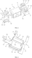
- Fig. 1 shows a structural schematic diagram of a forward and reverse rotation control device 100 according to some embodiments of the present disclosure.
- Fig. 2 shows a structural schematic diagram of a moving assembly 3 and a driving assembly 4 according to some embodiments of the present disclosure.
- Fig. 3 shows a structural schematic diagram of input and output members according to some embodiments of the present disclosure.
- the forward and reverse rotation control device 100 described herein generally includes a first housing 5, a first input member 11, a second input member 12, a first output member 21, a second output member 22, a moving assembly 3, and a driving assembly 4.
- the first housing 5 serves as a mounting carrier for arranging the first input member 11, the second input member 12, the first output member 21, the second output member 22, the moving assembly 3, and the driving assembly 4.
- the first input member 11 is connected to a first power supply line
- the second input member 12 is connected to a second power supply line.
- the first output member 21 and the second output member 22 are respectively connected to input ends of the power-using equipment.
- the forward and reverse rotation control device 100 of the embodiments of the present disclosure is suitable for various types of motors.
- the number of the input and output members is three, that is, when the input members include the first input member 11, the second input member 12, and a third input member (not shown in the figure) and the output members include the first output member 21, the second output member 22, and a third output member (not shown in the figure)
- the forward and reverse rotation control device 100 is suitable for a three-phase motor.
- the third input member is electrically connected to a third power supply line
- the third output member is connected to the input end of the power-using equipment
- the third input member is always connected to the third output member.
- the forward and reverse rotation control device 100 may change the phase sequence of the windings of the motor by changing the connecting relationship between two sets of input members (the first input member 11 and the second input member 12) and output members (the first output member 21 and the second output member 22), without the need of changing the connecting relationship between all three sets of input members and output members.
- the third input member and the third output member may pass through the first housing 5 and form a whole with the first housing 5. In other embodiments, the third input member and the third output member may also be separated from the first housing 5 without passing through it.
- the moving assembly 3 may be switched between a first connecting position and a second connecting position to change the connecting relationship between the first and second input members 11, 12 and the first and second output members 21, 22.
- the moving assembly 3 When the moving assembly 3 is in the first connecting position, the moving assembly 3 connects the first input member 11 to the first output member 21 and connects the second input member 12 to the second output member 22.
- the moving assembly 3 In a case that the moving assembly 3 is in the second connecting position, the moving assembly 3 connects the first input member 11 to the second output member 22 and connects the second input member 12 to the first output member 21.
- the forward and reverse rotation control device 100 of the embodiments of the present disclosure may change the phase sequence of the windings of the motor by changing the different connecting relationships between the input and output members, thereby controlling the forward and reverse rotation of the motor. Regardless of whether the moving assembly is in the first connecting position or the second connecting position, each input member is only conductive with the corresponding output member, without the need of installing an interlocking module.
- the forward and reverse rotation control device 100 has a simple structure and does not occupy mounting space.
- the moving assembly 3 includes a driving shaft 31 and a first mounting part 32 and a second mounting part 33 connected to the driving shaft 31.
- the driving assembly 4 is connected to the driving shaft 31 and may drive the driving shaft 31 to move in its axial direction, so that the first mounting part 32 and the second mounting part 33 may move together with the driving shaft 31, thereby enabling the moving assembly 3 to switch between the first connecting position and the second connecting position.
- the first input member 11 includes a first input end 111 and a first connecting part 112 connected to the first input end 111.
- the first input end 111 is electrically connected to the first power supply line.
- the second input member 12 includes a second input end 121 and a second connecting part 122 connected to the second input end 121.
- the second input end 121 is electrically connected to the second power supply line.
- the first output member 21 includes a first output end 211 and a third connecting part 212 connected to the first output end 211.
- the first output end 211 is adapted to be connected to the input end of the power-using equipment.
- the second output member 22 includes a second output end 221 and a fourth connecting part 222 connected to the second output end 221.
- the second output end 221 is adapted to be connected to the input end of the power-using equipment.
- the third input member includes a third input end and a fifth connecting part connected to the third input end.
- the third input end is electrically connected to the third power supply line.
- the third output member includes a third output end and a sixth connecting part connected to the third output end.
- the third output end is adapted to be connected to the input end of the power-using equipment.
- the position relationship between the input and output members may be changed as needed, as long as it may be ensured that the first input member 11 is connected to the first output member 21 and the second input member 12 is connected to the second output member 22 when the moving assembly 3 is in the first connecting position, and the moving assembly 3 connects the first input member 11 to the second output member 22 and connects the second input member 12 to the first output member 21 when the moving assembly 3 is in the second connecting position.
- the moving assembly 3 in a case that the moving assembly 3 is in the first connecting position, the moving assembly 3 connects the first connecting part 112 to the third connecting part 212 and connects the second connecting part 122 to the fourth connecting part 222. In a case that the moving assembly 3 is in the second connecting position, the moving assembly 3 connects the first connecting part 112 to the fourth connecting part 222 and connects the second connecting part 122 to the third connecting part 212.
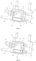
- Fig. 4 shows a structural schematic diagram of the input members, the output members, the driving assembly 4, and a portion of the moving assembly 3 according to some embodiments of the present disclosure, wherein the moving assembly 3 is in the first connecting position and the first mounting part 32 and the second mounting part 33 of the moving assembly 3 are not shown.
- Fig. 5 shows a structural schematic diagram of input members, output members, the driving assembly 4, and a portion of the moving assembly 3 according to some embodiments of the present disclosure, wherein the moving assembly is in a second connecting position and the first mounting part 32 and the second mounting part 33 of the moving assembly 3 are not shown. The first mounting part 32 and the second mounting part 33 of the moving assembly 3 are not shown in Figs.
- the first mounting part 32 is provided with a first conducting member 321 and a second conducting member 322, and the second mounting part 33 is provided with a third conducting member 331 and a fourth conducting member 332.
- a first end of the first conducting member 321 is arranged in correspondence to a first end of the first connecting part 112, and a second end of the first conducting member 321 is arranged in correspondence to a first end of the third connecting part 212.
- a first end of the second conducting member 322 is arranged in correspondence to a first end of the fourth connecting part 222, and a second end of the second conducting member 322 is arranged in correspondence to a first end of the second connecting part 122.
- a first end of the third conducting member 331 is arranged in correspondence to a second end of the first connecting part 112, and a second end of the third conducting member 331 is arranged in correspondence to a second end of the fourth connecting part 222.
- a first end of the fourth conducting member 332 is arranged in correspondence to a second end of the third connecting part 212, and a second end of the fourth conducting member 332 is arranged in correspondence to a second end of the second connecting part 122.
- the first end of the first conducting member 321 is connected to the first end of the first connecting part 112, and the second end of the first conducting member 321 is connected to the first end of the third connecting part 212.
- the first end of the second conducting member 322 is connected to the first end of the fourth connecting part 222, and the second end of the second conducting member 322 is connected to the first end of the second connecting part 122.
- the first end of the third conducting member 331 is spaced apart from the second end of the first connecting part 112, and the second end of the third conducting member 331 is spaced apart from the second end of the fourth connecting part 222.
- the first end of the fourth conducting member 332 is spaced apart from the second end of the third connecting part 212, and the second end of the fourth conducting member 332 is spaced apart from the second end of the second connecting part 122. Therefore, the first conducting member 321 connects the first connecting part 112 to the third connecting part 212, and the first input end 111, the first connecting part 112, the first conducting member 321, the third connecting part 212, and the first output end 211 form a conductive path, that is, the first input member 11 is connected to the first output member 21.
- the second conducting member 322 connects the second connecting part 122 to the fourth connecting part 222, and the second input end 121, the second connecting part 122, the second conducting member 322, the fourth connecting part 222, and the second output end 221 form a conductive path, that is, the second input member 12 is connected to the second output member 22.
- the first end of the first conducting member 321 is spaced apart from the first end of the first connecting part 112, and the second end of the first conducting member 321 is spaced apart from the first end of the third connecting part 212.
- the first end of the second conducting member 322 is spaced apart from the first end of the fourth connecting part 222, and the second end of the second conducting member 322 is spaced apart from the first end of the second connecting part 122.
- the first end of the third conducting member 331 is connected to the second end of the first connecting part 112, and the second end of the third conducting member 331 is connected to the second end of the fourth connecting part 222.
- the first end of the fourth conducting member 332 is connected to the second end of the third connecting part 212, and the second end of the fourth conducting member 332 is connected to the second end of the second connecting part 122. Therefore, the third conducting member 331 connects the first connecting part 112 to the fourth connecting part 222, and the first input end 111, the first connecting part 112, the third conducting member 331, the fourth connecting part 222, and the second output end 221 form a conductive path, that is, the first input member 11 is connected to the second output member 22.
- the fourth conducting member 332 connects the second connecting part 122 to the third connecting part 212, and the second input end 121, the second connecting part 122, the fourth conducting member 332, the third connecting part 212, and the first output end 211 form a conductive path, that is, the second input member 12 is connected to the first output member 21.
- first input member 11, the second input member 12, the first output member 21, and the second output member 22 are not limited to the structure as shown in Fig. 3 .
- Other structural features are also possible, as long as it may ensure that, in a case that the moving assembly 3 is in the first and second connecting positions, the connecting relationship between the first and second input members 11, 12 and the first and second output members 21, 22 meets the connecting relationship of the structure as shown in Fig. 3 .
- embodiments of the present disclosure change the connecting relationship between the first and second input members 11, 12 and the first and second output members 21, 22 by changing the different positions of the moving assembly 3, thereby changing the phase sequence of the windings of the motor and ultimately achieving the requirements of controlling the forward and reverse rotation of the motor.
- end faces of the first and second ends of the first conducting member 321 facing towards the first input member 11 are provided with first contacts.
- End faces of the first and second ends of the second conducting member 322 facing towards the first input member 11 are provided with first contacts.
- End faces of the first and second ends of the third conducting member 331 facing towards the first input member 11 are provided with first contacts.
- End faces of the first and second ends of the fourth conducting member 332 facing towards the first input member 11 are provided with first contacts.
- the first and second ends of the first input member 11, the second input member 12, the first output member 21, and the second output member 22 are also provided with second contacts that are matched with the corresponding first contacts to ensure that they meet a tight fitting requirement when in contact with each other.
- the first mounting part 32 is provided with a first mounting hole 323 and a second mounting hole 325.
- the second mounting part 33 is provided with a third mounting hole 333 and a fourth mounting hole 335.
- the first conducting member 321 is arranged in the first mounting hole 323.
- the second conducting member 322 is arranged in the second mounting hole 325.
- the third conducting member 331 is arranged in the third mounting hole 333.
- the fourth conducting member 332 is arranged in the fourth mounting hole 335.
- a first elastic member 324 is arranged within the first mounting hole 323.
- An end of the first elastic member 324 is connected to an inner wall surface of the first mounting hole 323, and the other end of the first elastic member 324 is arranged at a side of the first conducting member 321 away from the driving assembly 4.
- the moving assembly 3 continues to move along the axial direction of the driving shaft 31, and the first conducting member 321 may move in the first mounting hole 323 and press the first elastic member 324.
- a reaction force of the first elastic member 324 causes the first conducting member 321 to come into closer contact with the first connecting part 112 and the third connecting part 212.
- a second elastic member 326 is arranged within the second mounting hole 325. An end of the second elastic member 326 is connected to an inner wall surface of the second mounting hole 325, and the other end of the second elastic member 326 is arranged at a side of the second conducting member 322 away from the driving assembly 4.
- a third elastic member 334 is arranged within the third mounting hole 333.
- An end of the third elastic member 334 is connected to an inner wall surface of the third mounting hole 333, and the other end of the third elastic member 334 is arranged at a side of the third conducting member 331 away from the driving assembly 4.
- a fourth elastic member 336 is arranged within the fourth mounting hole 335. An end of the fourth elastic element 336 is connected to an inner wall surface of the fourth mounting hole 335, and the other end of the fourth elastic element 336 is arranged at a side of the fourth conducting member 332 away from the driving assembly 4.
- the second elastic member 326, the third elastic member 334, and the fourth elastic member 336 may achieve similar effects as the first elastic member 324, all of which ensure the tight fitting requirement between the conducting members and the connecting parts, which will not be described in detail here.
- the forward and reverse rotation control device 100 also includes a sensor (not shown in the figures), which may be mounted inside or outside the first housing 5.
- the sensor is used to detect the position of the driving shaft 31. That is to say, the sensor may detect that the moving assembly 3 is in the first and second connecting positions, and a controller connected to the sensor may then determine whether the moving assembly 3 is in the first or second connecting position.
- the senor is arranged outside the first housing 5. In a case that the sensor is arranged outside the first housing 5, the driving shaft 31 passes through the first housing 5. As shown in Fig. 1 , in other embodiments, the sensor is arranged inside the first housing 5.
- the driving assembly 4 is connected to the moving assembly 3.
- the driving assembly 4 may drive the moving assembly 3 to switch between the first and second connecting positions, thereby controlling the forward and reverse rotation of the motor.
- the driving assembly 4 may be various types of driving assemblies that are currently known or available in the future, as long as they may drive the moving assembly 3 to move. Embodiments of the present disclosure are not intended to be limited in this respect.
- the driving assembly 4 may include a bistable permanent magnet mechanism.
- the driving assembly 4 may also include a dual coil permanent magnet mechanism, an electric push rod, a hydraulic push rod, or an electromagnetic push rod.
- the working principle will be mainly described in the scenario of the driving assembly 4 including the bistable permanent magnet mechanism. Other situations will not be described in detail hereafter.
- the driving assembly 4 includes the bistable permanent magnet mechanism, the driving assembly 4 is located between the first mounting part 32 and the second mounting part 33. In a case that the driving assembly 4 includes the electric push rod, the hydraulic push rod, or the electromagnetic push rod, the driving assembly 4 is located at an end of the first mounting part 32 away from the second mounting part 33, or at an end of the second mounting part 33 away from the first mounting part 32.
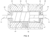
- Fig. 6 shows a cross-sectional view of the driving assembly 4 and the driving shaft 31 according to some embodiments of the present disclosure.
- the driving assembly 4 includes a bistable permanent magnet mechanism.
- the bistable permanent magnet mechanism is located between the first mounting part 32 and the second mounting part 33.
- the bistable permanent magnet mechanism includes a second housing 41, a coil 42, a moving iron core 43, a first magnetizer 44, a second magnetizer 45, a support frame 48, and two permanent magnets 46.
- the coil 42, the moving iron core 43, the first magnetizer 44, the second magnetizer 45, the permanent magnets 46, and the support frame 48 are all located inside the second housing 41.
- the coil 42 and the permanent magnets 46 are both arranged inside the support frame 48.
- the permanent magnets 46 are arranged in the middle position of the coil 42, and a circular channel for the movement of the moving iron core 43 is arranged inside the support frame 48.
- the first magnetizer 44 is arranged at an end of the circular channel
- the second magnetizer 45 is arranged at the other end of the circular channel
- the moving iron core 43 is located between the first magnetizer 44 and the second magnetizer 45, so that the support frame 48, the first magnetizer 44, and the second magnetizer 45 together form a motion space 47, thereby enabling the moving iron core 43 to move within the motion space 47.
- the permanent magnets 46 may also include two or more magnets, for example, in a case that the permanent magnets 46 includes three magnets, one permanent magnet 46 is arranged at a side of the moving iron core 43, and two permanent magnets 46 are arranged at the other side. In a case that the permanent magnets 46 includes more than three magnets, the arrangement manner of the permanent magnets 46 is similar and will not be repeated here. In addition, magnetic poles of adjacent ends of the permanent magnets 46 at both sides should be the same.
- the direction of the electromagnetic field generated by the current through the coil 42 is opposite to the direction of the magnetic field generated by the permanent magnets 46 in a position where the moving iron core 43 is adjacent/attached to the first conductor 44, so as to counteract the magnetic field generated by the permanent magnets 46 and generate a rightward electromagnetic force on the moving iron core 43.
- the combined action of the electromagnetic force and the elastic member on the moving assembly 3 drives the moving iron core 43 to move rightwards.
- the moving iron core 43 moves close to the second magnetizer 45, the permanent magnets 46, the second magnetizer 45, the second housing 41, and the moving iron core 43 form a second magnetic loop.
- the electromagnetic force exerted by the coil 42 on the moving iron core 43 and the magnetic force exerted by the second magnetic loop of the permanent magnets 46 on the moving iron core 43 increase, causing the moving iron core 43 to move rightwards at an increased speed and reach a position adjacent/attached to the second magnetizer 45.
- the permanent magnets 46 maintain the moving iron core 43 in a position adjacent/attached to the second magnetizer 45.
- a reverse current may be applied to the coil 42, which will not be described in detail here. It may be understood that on the one hand, the position movement of the moving iron core 43 may be achieved through the bistable permanent magnet mechanism, thereby achieving the switching of the moving assembly 3 between the first connecting position and the second connecting position. On the other hand, in a case that the bistable permanent magnet mechanism stops applying current to the coil 42, the position of the moving iron core 43 at both ends may be maintained by the permanent magnets 46, without the need for continuous power supply, thereby reducing the use cost.
- the driving shaft 31 may be made of magnetic conductive materials, such as the same material as the moving iron core 43. In other embodiments, the driving shaft 31 may also be made of non-magnetic conductive materials, and the embodiments of the present disclosure are not intended to be limited in this respect.
- the number of the driving shaft 31 is one, and the driving shaft 31 passes through the moving iron core 43, while also passing through the second housing 41, the first magnetizer 44, and the second magnetizer 45.
- the driving shaft 31 may be integrally formed with the moving iron core 43 and may also be the same member as the moving iron core 43.
- the number of the driving shafts 31 is two, and along the axial direction of the circular channel, the driving shafts 31 are respectively arranged at both ends of the moving iron core 43.
- the arrangement manner of the driving shafts 31 includes but is not limited to welding and connecting through connectors.
- the driving shaft 31 located at an end of the moving iron core 43 passes through the second housing 41 and the first magnetizer 44, and the driving shaft 31 located at the other end of the moving iron core 43 passes through the second housing 41 and the second magnetizer 45.
- the moving iron core 43 may drive the driving shafts 31 to move while moving within the motion space 47.
- the forward and reverse rotation control device 100 may be applied to various motors, such as three-phase motors. It should be understood that the forward and reverse rotation control device 100 according to the embodiments of the present disclosure may also be applied to other power-using equipment, and the embodiments of the present disclosure are not intended to be limited in this respect.
Landscapes
- Engineering & Computer Science (AREA)
- Power Engineering (AREA)
- Connection Of Motors, Electrical Generators, Mechanical Devices, And The Like (AREA)
Applications Claiming Priority (1)
| Application Number | Priority Date | Filing Date | Title |
|---|---|---|---|
| CN202310898984.9A CN119341436A (zh) | 2023-07-20 | 2023-07-20 | 正反转控制装置 |
Publications (1)
| Publication Number | Publication Date |
|---|---|
| EP4496190A1 true EP4496190A1 (fr) | 2025-01-22 |
Family
ID=89030079
Family Applications (1)
| Application Number | Title | Priority Date | Filing Date |
|---|---|---|---|
| EP23213037.7A Pending EP4496190A1 (fr) | 2023-07-20 | 2023-11-29 | Dispositif de commande de rotation avant et arrière |
Country Status (3)
| Country | Link |
|---|---|
| US (1) | US12401306B2 (fr) |
| EP (1) | EP4496190A1 (fr) |
| CN (1) | CN119341436A (fr) |
Citations (1)
| Publication number | Priority date | Publication date | Assignee | Title |
|---|---|---|---|---|
| CN206759355U (zh) * | 2017-03-23 | 2017-12-15 | 深圳市柏盛高科技有限公司 | 可驱动马达双向转动的电源 |
Family Cites Families (2)
| Publication number | Priority date | Publication date | Assignee | Title |
|---|---|---|---|---|
| US12088222B2 (en) * | 2019-01-28 | 2024-09-10 | Ridge Tool Company | Soft start for power tool with momentary switch and mechanical direction selection switch |
| EP4014311A4 (fr) * | 2019-08-16 | 2023-07-26 | Milwaukee Electric Tool Corporation | Sélection de mode d'un outil électrique |
-
2023
- 2023-07-20 CN CN202310898984.9A patent/CN119341436A/zh active Pending
- 2023-11-28 US US18/521,755 patent/US12401306B2/en active Active
- 2023-11-29 EP EP23213037.7A patent/EP4496190A1/fr active Pending
Patent Citations (1)
| Publication number | Priority date | Publication date | Assignee | Title |
|---|---|---|---|---|
| CN206759355U (zh) * | 2017-03-23 | 2017-12-15 | 深圳市柏盛高科技有限公司 | 可驱动马达双向转动的电源 |
Also Published As
| Publication number | Publication date |
|---|---|
| CN119341436A (zh) | 2025-01-21 |
| US20250030367A1 (en) | 2025-01-23 |
| US12401306B2 (en) | 2025-08-26 |
Similar Documents
| Publication | Publication Date | Title |
|---|---|---|
| US9029718B2 (en) | Common actuator system of multi switches for switchgear | |
| US11289294B2 (en) | Rotary switch and circuit interrupter including the same | |
| CN103854887B (zh) | 带有并联电容器的气路遮断器 | |
| EP2835811A1 (fr) | Disjoncteur à gaz | |
| US12401306B2 (en) | Forward and reverse rotation control device | |
| CN103854914A (zh) | 气体断路器 | |
| CN115132524A (zh) | 双电磁回路控制的具有串联和并联触头的继电器 | |
| CN119208083A (zh) | 磁路系统和电磁继电器 | |
| EP3688864B1 (fr) | Actionneur à réluctance variable | |
| TW201443963A (zh) | 三相共槽型斷路器 | |
| EP3678159B1 (fr) | Approches de relais à trois états améliorées pour des applications ou des appareils automobiles | |
| CN210805494U (zh) | 干式变压器有载调容过渡装置及调容变压器 | |
| CN110993392B (zh) | 干式变压器有载调容开关及变压器 | |
| JPS63163042A (ja) | リニアアクチユエ−タ | |
| KR100625524B1 (ko) | 중전압급 차단기용 자석형 조작기 | |
| CN111029117B (zh) | 干式变压器有载调容过渡装置及调容变压器 | |
| EP3672042A1 (fr) | Actionneur pour un disjoncteur moyenne tension | |
| CN222927385U (zh) | 磁路系统和电磁继电器 | |
| US12401178B2 (en) | Opening and closing mechanism and leakage protection device | |
| CN215869246U (zh) | 开合机构以及漏电保护设备 | |
| CN101465588A (zh) | 一种磁阻电动机及提高电动机有效功率的方法 | |
| WO2026082606A1 (fr) | Relais de dérivation rapide | |
| EP1280176B1 (fr) | Contacteur basse tension | |
| CN115841930A (zh) | 一种分相独立电磁机构控制的三相开关 | |
| RU2067897C1 (ru) | Электромеханический преобразователь |
Legal Events
| Date | Code | Title | Description |
|---|---|---|---|
| PUAI | Public reference made under article 153(3) epc to a published international application that has entered the european phase |
Free format text: ORIGINAL CODE: 0009012 |
|
| STAA | Information on the status of an ep patent application or granted ep patent |
Free format text: STATUS: THE APPLICATION HAS BEEN PUBLISHED |
|
| AK | Designated contracting states |
Kind code of ref document: A1 Designated state(s): AL AT BE BG CH CY CZ DE DK EE ES FI FR GB GR HR HU IE IS IT LI LT LU LV MC ME MK MT NL NO PL PT RO RS SE SI SK SM TR |
|
| STAA | Information on the status of an ep patent application or granted ep patent |
Free format text: STATUS: REQUEST FOR EXAMINATION WAS MADE |
|
| 17P | Request for examination filed |
Effective date: 20250715 |