EP4496422A1 - Procédé de commutation entre uu et pc5 - Google Patents
Procédé de commutation entre uu et pc5 Download PDFInfo
- Publication number
- EP4496422A1 EP4496422A1 EP23771032.2A EP23771032A EP4496422A1 EP 4496422 A1 EP4496422 A1 EP 4496422A1 EP 23771032 A EP23771032 A EP 23771032A EP 4496422 A1 EP4496422 A1 EP 4496422A1
- Authority
- EP
- European Patent Office
- Prior art keywords
- path
- unicast link
- link
- switching
- communication
- Prior art date
- Legal status (The legal status is an assumption and is not a legal conclusion. Google has not performed a legal analysis and makes no representation as to the accuracy of the status listed.)
- Pending
Links
Images







Classifications
-
- H—ELECTRICITY
- H04—ELECTRIC COMMUNICATION TECHNIQUE
- H04W—WIRELESS COMMUNICATION NETWORKS
- H04W76/00—Connection management
- H04W76/20—Manipulation of established connections
- H04W76/25—Maintenance of established connections
-
- H—ELECTRICITY
- H04—ELECTRIC COMMUNICATION TECHNIQUE
- H04W—WIRELESS COMMUNICATION NETWORKS
- H04W76/00—Connection management
- H04W76/10—Connection setup
- H04W76/14—Direct-mode setup
-
- H—ELECTRICITY
- H04—ELECTRIC COMMUNICATION TECHNIQUE
- H04W—WIRELESS COMMUNICATION NETWORKS
- H04W12/00—Security arrangements; Authentication; Protecting privacy or anonymity
- H04W12/04—Key management, e.g. using generic bootstrapping architecture [GBA]
- H04W12/047—Key management, e.g. using generic bootstrapping architecture [GBA] without using a trusted network node as an anchor
-
- H—ELECTRICITY
- H04—ELECTRIC COMMUNICATION TECHNIQUE
- H04W—WIRELESS COMMUNICATION NETWORKS
- H04W36/00—Hand-off or reselection arrangements
- H04W36/03—Reselecting a link using a direct mode connection
-
- H—ELECTRICITY
- H04—ELECTRIC COMMUNICATION TECHNIQUE
- H04W—WIRELESS COMMUNICATION NETWORKS
- H04W36/00—Hand-off or reselection arrangements
- H04W36/03—Reselecting a link using a direct mode connection
- H04W36/033—Reselecting a link using a direct mode connection in pre-organised networks
-
- H—ELECTRICITY
- H04—ELECTRIC COMMUNICATION TECHNIQUE
- H04W—WIRELESS COMMUNICATION NETWORKS
- H04W36/00—Hand-off or reselection arrangements
- H04W36/03—Reselecting a link using a direct mode connection
- H04W36/037—Reselecting a link using a direct mode connection by reducing handover delay, e.g. latency
-
- H—ELECTRICITY
- H04—ELECTRIC COMMUNICATION TECHNIQUE
- H04W—WIRELESS COMMUNICATION NETWORKS
- H04W40/00—Communication routing or communication path finding
- H04W40/02—Communication route or path selection, e.g. power-based or shortest path routing
- H04W40/12—Communication route or path selection, e.g. power-based or shortest path routing based on transmission quality or channel quality
-
- H—ELECTRICITY
- H04—ELECTRIC COMMUNICATION TECHNIQUE
- H04W—WIRELESS COMMUNICATION NETWORKS
- H04W76/00—Connection management
- H04W76/20—Manipulation of established connections
-
- H—ELECTRICITY
- H04—ELECTRIC COMMUNICATION TECHNIQUE
- H04W—WIRELESS COMMUNICATION NETWORKS
- H04W76/00—Connection management
- H04W76/20—Manipulation of established connections
- H04W76/23—Manipulation of direct-mode connections
-
- H—ELECTRICITY
- H04—ELECTRIC COMMUNICATION TECHNIQUE
- H04W—WIRELESS COMMUNICATION NETWORKS
- H04W12/00—Security arrangements; Authentication; Protecting privacy or anonymity
- H04W12/04—Key management, e.g. using generic bootstrapping architecture [GBA]
- H04W12/041—Key generation or derivation
-
- H—ELECTRICITY
- H04—ELECTRIC COMMUNICATION TECHNIQUE
- H04W—WIRELESS COMMUNICATION NETWORKS
- H04W12/00—Security arrangements; Authentication; Protecting privacy or anonymity
- H04W12/10—Integrity
-
- H—ELECTRICITY
- H04—ELECTRIC COMMUNICATION TECHNIQUE
- H04W—WIRELESS COMMUNICATION NETWORKS
- H04W92/00—Interfaces specially adapted for wireless communication networks
- H04W92/16—Interfaces between hierarchically similar devices
- H04W92/18—Interfaces between hierarchically similar devices between terminal devices
Definitions
- the present specification relates to mobile communications.
- 3rd generation partnership project (3GPP) long-term evolution (LTE) is a technology for enabling high-speed packet communications.
- 3GPP 3rd generation partnership project
- LTE long-term evolution
- Many schemes have been proposed for the LTE objective including those that aim to reduce user and provider costs, improve service quality, and expand and improve coverage and system capacity.
- the 3GPP LTE requires reduced cost per bit, increased service availability, flexible use of a frequency band, a simple structure, an open interface, and adequate power consumption of a terminal as an upper-level requirement.
- ITU international telecommunication union
- NR new radio
- 3GPP has to identify and develop the technology components needed for successfully standardizing the new RAT timely satisfying both the urgent market needs, and the more long-term requirements set forth by the ITU radio communication sector (ITU-R) international mobile telecommunications (IMT)-2020 process.
- ITU-R ITU radio communication sector
- IMT international mobile telecommunications
- the NR should be able to use any spectrum band ranging at least up to 100 GHz that may be made available for wireless communications even in a more distant future.
- the NR targets a single technical framework addressing all usage scenarios, requirements and deployment scenarios including enhanced mobile broadband (eMBB), massive machine-type-communications (mMTC), ultra-reliable and low latency communications (URLLC), etc.
- eMBB enhanced mobile broadband
- mMTC massive machine-type-communications
- URLLC ultra-reliable and low latency communications
- the NR shall be inherently forward compatible.
- FIG. 1 shows an example of a communication system to which implementations of the present disclosure is applied.
- Three main requirement categories for 5G include (1) a category of enhanced mobile broadband (eMBB), (2) a category of massive machine type communication (mMTC), and (3) a category of ultra-reliable and low latency communications (URLLC).
- eMBB enhanced mobile broadband
- mMTC massive machine type communication
- URLLC ultra-reliable and low latency communications
- the BSs 200 and the network 300 may be implemented as wireless devices and a specific wireless device may operate as a BS/network node with respect to other wireless devices.
- the XR device may include an AR/VR/Mixed Reality (MR) device and may be implemented in the form of a head-mounted device (HMD), a head-up display (HUD) mounted in a vehicle, a television, a smartphone, a computer, a wearable device, a home appliance device, a digital signage, a vehicle, a robot, etc.
- the hand-held device may include a smartphone, a smartpad, a wearable device (e.g., a smartwatch or a smartglasses), and a computer (e.g., a notebook).
- the home appliance may include a TV, a refrigerator, and a washing machine.
- the IoT device may include a sensor and a smartmeter.
- the wireless devices 100a to 100f may be called user equipments (UEs).
- a UE may include, for example, a cellular phone, a smartphone, a laptop computer, a digital broadcast terminal, a personal digital assistant (PDA), a portable multimedia player (PMP), a navigation system, a slate personal computer (PC), a tablet PC, an ultrabook, a vehicle, a vehicle having an autonomous traveling function, a connected car, an UAV, an AI module, a robot, an AR device, a VR device, an MR device, a hologram device, a public safety device, an MTC device, an IoT device, a medical device, a FinTech device (or a financial device), a security device, a weather/environment device, a device related to a 5G service, or a device related to a fourth industrial revolution field.
- PDA personal digital assistant
- PMP portable multimedia player
- PC slate personal computer
- tablet PC a tablet PC
- ultrabook a vehicle, a vehicle having an autonomous
- the UAV may be, for example, an aircraft aviated by a wireless control signal without a human being onboard.
- the FinTech device may be, for example, a device capable of providing a financial service such as mobile payment.
- the FinTech device may include a payment device or a point of sales (POS) system.
- POS point of sales
- the weather/environment device may include, for example, a device for monitoring or predicting a weather/environment.
- Robot means a machine that automatically processes or operates a given task by its own ability.
- robots with the ability to recognize the environment and make self-determination to perform actions can be called intelligent robots.
- Robots can be classified as industrial, medical, home, military, etc., depending on the purpose or area of use.
- the robot can perform a variety of physical operations, such as moving the robot joints with actuators or motors.
- the movable robot also includes wheels, brakes, propellers, etc., on the drive, allowing it to drive on the ground or fly in the air.
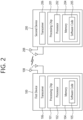
- the one or more transceivers 106, 206 may be associated with one or more antennas 108, 208. Additionally and/or alternatively, the one or more transceivers 106, 206 may include one or more antennas 108, 208. The one or more transceivers 106, 206 may be configured to transmit and receive, via the one or more antennas 108, 208, user data, control information, wireless signals/channels, etc. referred to in the descriptions, features, procedures, suggestions, methods, and/or flowcharts of operation disclosed herein. As used herein, the one or more antennas 108, 208 may be a plurality of physical antennas, or a plurality of logical antennas (e.g., antenna ports).
- the one or more transceivers 106, 206 may convert the received user data, control information, radio signals/channels, etc. from RF band signals to baseband signals in order to process the received user data, control information, radio signals/channels, etc. using the one or more processors 102, 202.
- the one or more transceivers 106, 206 may convert the processed user data, control information, radio signals/channels, etc. from baseband signals to RF band signals using the one or more processors 102, 202. To do so, the one or more transceivers 106, 206 may include (analog) oscillators and/or filters.
- the one or more transceivers 106, 206 may up-convert an OFDM baseband signal to an OFDM signal via an (analog) oscillator and/or filter under the control of the one or more processors 102, 202, and transmit the up-converted OFDM signal at the carrier frequency.
- the one or more transceivers 106, 206 may receive the OFDM signal at the carrier frequency and, under the control of the one or more processors 102, 202, down-convert the OFDM signal to an OFDM baseband signal via an (analog) oscillator and/or filter.
- the wireless devices 100 and 200 may further include additional components.
- the additional components 140 may be variously configured according to types of the wireless devices 100 and 200.
- the additional components 140 may include at least one of a power unit/battery, an Input/Output (I/O) device (e.g., audio I/O port, video I/O port), a driving device, and a computing device.
- the additional components 140 may be coupled to the one or more processors 102 and 202 via various technologies, such as a wired or wireless connection.
- the processor(s) 202 connected to, mounted on or launched in the second wireless device 200 may be adapted to perform the BS behavior according to an implementation of the present disclosure or control the transceiver(s) 206 to perform the BS behavior according to an implementation of the present disclosure.
- FIG. 3 shows an example of UE to which implementations of the present disclosure is applied.
- FIG. 3 shows an example of UE to which implementations of the present disclosure is applied.
- a UE 100 may correspond to the first wireless device 100 of FIG. 2 .
- a UE 100 includes a processor 102, a memory 104, a transceiver 106, one or more antennas 108, a power management module 141, a battery 142, a display 143, a keypad 144, a Subscriber Identification Module (SIM) card 145, a speaker 146, and a microphone 147.
- SIM Subscriber Identification Module
- the processor 102 may be adapted to implement the descriptions, functions, procedures, suggestions, methods and/or operational flowcharts disclosed in the present disclosure.
- the processor 102 may be adapted to control one or more other components of the UE 100 to implement the descriptions, functions, procedures, suggestions, methods and/or operational flowcharts disclosed in the present disclosure.
- Layers of the radio interface protocol may be implemented in the processor 102.
- the processor 102 may include ASIC, other chipset, logic circuit and/or data processing device.
- the processor 102 may be an application processor.
- the processor 102 may include at least one of DSP, CPU, GPU, a modem (modulator and demodulator).
- processor 102 may be found in SNAPDRAGON TM series of processors made by Qualcomm ® , EXYNOS TM series of processors made by Samsung ® , A series of processors made by Apple ® , HELIO TM series of processors made by MediaTek ® , ATOM TM series of processors made by Intel ® or a corresponding next generation processor.
- the memory 104 is operatively coupled with the processor 102 and stores a variety of information to operate the processor 102.
- the memory 104 may include ROM, RAM, flash memory, memory card, storage medium and/or other storage device.
- modules e.g., procedures, functions, etc.
- the modules can be stored in the memory 104 and executed by the processor 102.
- the memory 104 can be implemented within the processor 102 or external to the processor 102 in which case those can be communicatively coupled to the processor 102 via various means as is known in the art.
- the power management module 141 manages power for the processor 102 and/or the transceiver 106.
- the battery 142 supplies power to the power management module 141.
- the speaker 146 outputs sound-related results processed by the processor 102.
- the microphone 147 receives sound-related inputs to be used by the processor 102.
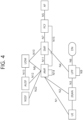
- FIG. 4 illustrates an example 5G system structure to which an implementation of the present specification may be applied.
- the 5G system (5GS; 5G system) structure consists of the following network functions (NFs).
- FIG. 4 shows the 5G system structure of a non-roaming case using a reference point representation that shows how various network functions interact with each other.
- UDSF, NEF and NRF are not described for clarity of the point-to-point diagram. However, all network functions shown may interact with UDSF, UDR, NEF and NRF as needed.
- connection between the UDR and other NFs is not shown in FIG. 4 .
- connection between NWDAF and other NFs is not shown in FIG. 4 .
- the 5G system architecture includes the following reference points.
- V2X (vehicle-to-everything) communication will be described.
- V2X communication the following definitions may be used:
- V2X communication via PC5 reference point There are two operation modes for V2X communication: V2X communication via PC5 reference point and V2X communication via Uu reference point. These two operation modes may be used independently by the UE for transmission and reception.
- V2X communication via PC5 reference point is supported by LTE and/or NR.
- V2X communication via Uu reference point is supported by E-UTRA connected to 5GC and/or NR connected to 5GC. V2X communication via Uu reference point may only be unicast.
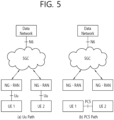
- the direct communication path switching scenario between PC5 and Uu refers to switching between (a) Uu path and (b) PC5 path in FIG. 5 .
- FIG. 7 shows procedure of 5G ProSe Direct Discovery with Model B.
- the Destination Layer-2 ID and Source Layer-2 ID are used to send the Solicitation message.
- Discoveree UE determines the Destination Layer-2 ID for signaling reception.
- the Discoveree UE that matches the solicitation message responds to the Discoverer UE with the Response message.
- the Response message may include Type of Discovery Message, ProSe Response Code, security protection element, [metadata information].
- the Application layer metadata information may be included as metadata in the Response message.
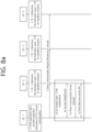
- FIG. 8a and FIG. 8b illustrate the Layer-2 link establishment procedure.
- the Direct Communication Request message includes:
- Target User Info is included in the Direct Communication Request message
- the target UE i.e. UE-2
- UE-1 sends the following information to the target UE:
- UE-1 When the security protection is enabled, UE-1 sends QoS Info to the target UE.
- UE-1 When the security protection is enabled, UE-1 sends Optional PC5 QoS Rule(s)to the target UE.
- the Direct Communication Accept message includes:
- the ProSe layer of the UE that established PC5 unicast link passes the PC5 Link Identifier assigned for the unicast link and the PC5 unicast link related information down to the AS layer.
- the PC5 unicast link related information includes Layer-2 ID information (i.e. source Layer-2 ID and destination Layer-2 ID). This enables the AS layer to maintain the PC5 Link Identifier together with the PC5 unicast link related information.
- ProSe data is transmitted over the established unicast link as below:
- UE-1 sends the ProSe data using the source Layer-2 ID (i.e. UE-1's Layer-2 ID for this unicast link) and the destination Layer-2 ID (i.e. the peer UE's Layer-2 ID for this unicast link).
- the source Layer-2 ID i.e. UE-1's Layer-2 ID for this unicast link
- the destination Layer-2 ID i.e. the peer UE's Layer-2 ID for this unicast link
- PC5 unicast link is bi-directional, therefore the peer UE of UE-1 can send the ProSe data to UE-1 over the unicast link with UE-1.
- the unicast mode security mechanism is used to provide unicast mode 5G ProSe Direct Communication security.
- the Key_Est_Info contains the different data that is required for key establishment. Such data is transparent to the PC5 layer, i.e. the PC5 layer does not need to understand the content of Key_Est_info.
- the endpoint in the UEs that understands the contents of Key_Est_Info may be an application on the UEs. Between the PC5 layer and the application layer on the vehicles, the information contained in Key_Est_Info can be passed in an implementation-specific manner, e.g. as one block or several IEs.
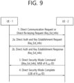
- FIG. 9 shows the message flow for the establishment of PC5 security key using a generic container.
- FIG. 9 shows the message flows for establishing security at PC5 using the key established at the layer above PC5.
- the need for both steps 2a and 2b (and the number of times both steps 2a and step 2b are run) depends on the authentication method being used.
- UE_1 shall send a Direct Security Mode Complete message to UE_2 which shall contain the LSB of K NRP ID.
- UE_2 shall form K NRP ID from its chosen MSB of K NRP ID and the received LSB of K NRP ID and shall store the complete K NRP ID with K NRP .
- FIG. 10 shows a Layer-2 link maintenance procedure.
- the PC5 Signaling Protocol shall support keep-alive functionality that is used to detect if a particular PC5 unicast link is still valid. Either side of the PC5 unicast link can initiate the layer-2 link maintenance procedure (i.e. keep-alive procedure), based on for example triggers from the AS layer or internal timers.
- the UEs shall minimize the keep-alive signaling, e.g. cancel the procedure if data are successfully received over the PC5 unicast link.
- UE-1 and UE-2 have an established unicast link.
- 5G ProSe direct link keep-alive procedure defined in clause 7.2.5 of TS 24.554 V1.1.0 may be applied to determine the exact triggers for the keep-alive messages.
- the trigger can be based on a timer associated with the Layer-2 link.
- the timer can be reset with a successful reception event defined by TS 38.300 [12].
- UE-2 Upon reception of the Keep-alive message, UE-2 responds with a Keep-alive Ack message.
- the UE initiating the keep-alive procedure shall determine the follow-up actions based on the result of the signalling, e.g. proceed with implicit layer-2 link release.
- 5G ProSe direct link keep-alive procedure defined in clause 7.2.5 of TS 24.554 V1.1.0 (2022-1) may be applied to determine the follow-up actions. For example, a successful reception event can also cancel the layer-2 link release if received in time.
- the method for supporting switching back from the proposed Uu path to the PC5 path may be composed of a combination of one or more of the following operations/configurations/steps.
- a path may mean a communication path, a routing path, a connection path, a reference point, an interface, etc.
- UE User Equipment
- terminal is used interchangeably.
- PC5 unicast link unicast link
- Layer-2 link PC5 unicast connection
- Layer-2 connection PC5 unicast connection
- the method for supporting switching back from the Uu path to the PC5 path may be applied not only to ProSe services but also to other services (e.g., UAS (Uncrewed Aerial Systems) services, V2X services, etc.).
- UAS Uncrewed Aerial Systems
- V2X services etc.
- the two UEs may switch the communication path from PC5 to Uu.
- the configured signal strength threshold may be provided to the UE as a 5G ProSe policy/parameter, may be provided by the NG-RAN, or may be implementation-specific information/value to the UE. This may be applied throughout this specification. Later, there may be a case where two UEs can communicate over the PC5 reference point with satisfactory signal strength. For example, because a temporary obstacle no longer exists between the two UEs. In order to switch back from Uu to PC5, the two UEs need to discover each other over the PC5 reference point and establish a unicast link again.
- the UE in order to switch from the Uu path to the PC5 path, The UE must discover whether the other UE is nearby through the ProSe Direct Discovery procedure, and when the other UE is detected as being in close proximity, a procedure to establish a PC5 unicast link between the two UEs must be performed.
- This PC5 unicast link establishment procedure may be completed by exchanging multiple PC5-S messages including the Security Establishment procedure.
- the PC5-S message is a control plane signaling message exchanged between UEs through the PC5 reference point to perform various procedures related to the PC5 unicast link (e.g., procedures such as PC5 unicast link formation, modification, maintenance, and release).
- the maintained unicast link may also be used to check whether it is possible to switch back to the PC5 path.
- the switching back method to the PC5 path proposed in this specification may be efficient because, as described above, two UEs do not need to perform the ProSe Direct Discovery procedure and the PC5 unicast link establishment procedure to switch from the Uu path to the PC5 path.
- the PC5 signal strength may mean the PC5 signal level, the PC5 signal quality, the Layer-2 link status/quality, or the unicast link status/quality.
- the unicast link may be released, and a UE may switch back from the Uu path to the PC5 path without reusing the unicast link.
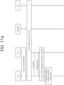
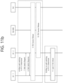
- FIG. 11a and FIG. 11b illustrate procedures according to the first embodiment.
- UE-1 and UE-2 may be served by the same PLMN or can be served by different PLMNs.
- UE-1 and UE-2 may not release the unicast link. In this case, the unicast link may be maintained.
- UE-1 and UE-2 may negotiate whether to maintain the unicast link after path switching to Uu.
- Maintaining a unicast link may be interpreted as suspending or holding the use of the unicast link. Maintaining a unicast link may be interpreted as maintaining the PC5 link identifier, Layer-2 ID, IP address (if it is an IP type Layer-2 link), etc. used for the unicast link.
- the negotiation may be performed through another existing Layer-2 link related procedure (e.g., Layer-2 link modification procedure) or may be performed through a newly defined procedure.
- Layer-2 link related procedure e.g., Layer-2 link modification procedure
- the negotiation may be initiated by UE-1 requesting to maintain the PC5 path (i.e., unicast link) or notifying UE-2 that it supports maintaining the PC5 path (i.e., unicast link) even after switching to the Uu path. Then, the negotiation may be performed by UE-2 responding to it (e.g., Ack/Accept/accept/support or Nack/Reject/not supporting). Or, conversely, the negotiation may be performed by UE-2 initiating the negotiation and UE-1 responding to it.
- UE-1 and UE-2 may exchange PC5-S messages to maintain the unicast link.
- the maintenance or negotiation may be based on various reasons/information as described above.
- the unicast link may be maintained after the path switching to Uu.
- a link identifier update for a unicast link procedure may or may not be performed.
- UE-1 may initiate a Layer-2 link maintenance procedure by sending a Keep-alive message to UE-2 to determine the status of the PC5 unicast link.
- the PC5 unicast link may be considered valid. Therefore, there is no need to transmit a keep-alive message.
- a Layer-2 link maintenance procedure may be performed to determine the status of the PC5 unicast link.
- a Layer-2 link maintenance procedure may be used.
- a newly defined procedure and/or newly defined messages e.g., PC5-S messages, PC5 discovery messages, user data/traffic, etc.
- the terminal may perform switching back by considering the switch-back-attempt timer and the good-link-quality counter.
- the terminal may attempt switching back based on the expiration of the switch-back-attempt timer.
- the UE may attempt to switch back. For example, if the signal strength of the PC5 link is higher than a configured threshold, the UE may increase the good-link-quality counter.
- the good-link-quality counter may have its maximum number. Based on the good-link-quality counter reaching its maximum number, the UE may attempt to switch back.
- the UE may start a switch-back-attempt timer. Additionally, the UE may set the good-link-quality counter to 0.
- the switch-back-attempt timer may be provided to UE-1 as a 5G ProSe policy/parameter.
- the switch-back-attempt timer may be provided by NG-RAN. Or, it may be an implementation-specific timer.
- the maximum number of the good-link-quality counter and the switch-back-attempt timer may be determined through negotiation between two UEs.
- the switch-back-attempt timer may be appropriately set considering the period of performing the Layer-2 link maintenance procedure, the maximum number of good-link-quality, etc.
- UE-2 may respond with a Keep-alive Ack message.
- the unicast link may be released locally.
- the unicast link may be released at the request of the application layer (or upper layer) of the UE.
- the unicast link may be released based on various reasons such as the related application being inactive or disabled, or there being no more traffic.
- UE-1 may check the PC5 signal level of the unicast link and perform the following based on the check result:
- the configured signal strength threshold may be the same information/value as the configured signal strength threshold that causes switching to the Uu path mentioned in step 2, or may be different information/value.
- the configured signal strength threshold for setting the good-link-quality counter to 0 may be set to a higher value than the configured signal strength threshold that causes switching to the Uu path.
- the configured signal strength threshold may be configured in the UE, provided by the NG-RAN, or provided by 5GC (e.g., as a ProSe Policy/Parameter).
- Layer-2 link maintenance procedure may be repeated until the good-link-quality counter reaches a maximum number of good-link-quality (e.g., 3, 5, 8, 10, etc.) or the switch-back-attempt timer expires.
- a maximum number of good-link-quality e.g., 3, 5, 8, 10, etc.
- the maximum number of good-link-quality may be typically set to a value greater than 1 to evaluate how stable the unicast link is (i.e., whether the PC5 signal strength is not consistently/consecutively lower than the configured signal strength threshold). However, it may also be set to 1.
- the maximum number of good-link-quality may be provided by UE-1 as a 5G ProSe Policy/Parameter. Or, the maximum number of good-link-quality may be provided by NG-RAN.
- UE-1 can decide whether to perform switching back to PC5 path as follows:
- the Layer-2 link maintenance procedure may have a maximum number of times it is allowed to be performed (e.g., 15 times, 20 times, etc.).
- UE-1 may decide to perform a switch back to PC5 path based on the signal strength of the maintained Layer-2 link (unicast link).
- Determining whether to perform a switch back to the PC5 path may be interpreted as determining whether switching to the PC5 path is possible, determining whether switching to the PC5 path is feasible, etc.
- not performing a switch back to the PC5 path may be interpreted as determining whether switching to the PC5 path is not possible, determining whether switching to the PC5 path is not feasible, etc.
- step 7 to step 10 described below may be performed.
- UE-1 may send a path switching request message to UE-2 to trigger a switch from Uu to PC5.
- UE-2 may respond with a path switching response message.
- UE-1 and UE-2 may exchange data over the unicast link.
- the above-mentioned path switching to PC5 may be interpreted as switching back to PC5 path, reusing the unicast link, resuming the unicast link, etc.
- path switching to PC5 may be performed by reusing the maintained unicast link.
- the Path Switch Request/Response message which is a PC5-S message used for path switching to PC5, may be an example.
- a message with a different name may be defined and used for path switching to PC5, or an existing PC5-S message may be utilized.
- the Path Switch Request message may include information indicating switching to PC5 path, information indicating reusing the unicast link, information indicating resuming the unicast link, etc.
- the Layer-2 link modification procedure may be performed instead of or after exchanging the Path Switch Request/Response message for path switching back to PC5.
- the PDU session of UE-2 used to communicate with UE-1 is no longer needed after path switching to PC5, the PDU session of UE-2 may be released.
- step 11 may be performed.
- the unicast link between UE-1 and UE-2 may be released.
- UE-1 determines whether to switch back to PC5 path, but UE-2 may also determine this. Or, after one UE decides to route switch back to PC5, it may make a final decision on route switching back to PC5 after confirming with the counterpart UE of the unicast link. Or, after one UE decides to route switch back to PC5, it may make a final decision on route switching back to PC5 after confirming with the network (NG-RAN or 5GC or Application Function/Application Server).
- NG-RAN or 5GC or Application Function/Application Server the network
- the two UEs may switch their communication path from PC5 to Uu. Later, there may be a case where the two UEs can communicate via the PC5 reference point with satisfactory signal strength, because the temporary obstacle between the two UEs no longer exists. In order to switch back from Uu to PC5, the two UEs must discover each other via the PC5 reference point and re-establish the unicast link. This may take some time. In addition, it may be uncertain when the UE(s) should trigger ProSe Direct Discovery or Layer-2 link establishment in order to communicate again via the PC5 reference point.
- the maintained unicast link may also be used to determine whether switching back to the PC5 path is possible.
- the unicast link After switching to the Uu path, the unicast link may be released, so that the unicast link may be switched back from the Uu path to the PC5 path without being reused.
- UE-1 and UE-2 may not release the unicast link. In this case, the unicast link may be maintained.
- UE-1 and UE-2 may negotiate whether to maintain the unicast link after path switching to Uu. The negotiation on whether to maintain the unicast link may be based on the Path Selection policy (e.g. PC5 preferred) and/or the Path Switching policy (e.g. direct PC5 allowed).
- the Path Selection policy e.g. PC5 preferred
- the Path Switching policy e.g. direct PC5 allowed
- UE-1 may initiate Layer-2 link maintenance procedure by sending Keep-alive message to UE-2 to determine the status of PC5 unicast link.
- the UE may initiate switch-back-attempt timer.
- the switch-back-attempt timer may be provided by 5G ProSe policy/parameter in UE-1.
- UE-2 may respond with Keep-alive Ack message.
- the unicast link may be released locally.
- UE-1 may measure PC5 signal level of unicast link.
- UE-1 may repeat Layer-2 link maintenance procedure until switch-back-attempt timer expires.
- UE-1 may determine whether to perform switching back to the PC5 path.
- UE-1 may measure the PC5 signal strength of the unicast link with UE-2 through the Layer-2 link maintenance procedure at least once until the switch-back-attempt timer expires. Based on the measured result, UE-1 may determine whether to switch to the PC5 path. For example, if i) the measured PC5 signal strength is determined to be good at least once, ii) is determined to be stable, or iii) is determined to be not lower than the set signal strength threshold, UE-1 may determine to switch to the PC5 path.
- UE-1 may determine not to switch to the PC5 path.
- the switch-back-attempt timer may not be applied or considered.
- UE-1 may measure the PC5 signal strength of the unicast link with UE-2 through one or more Layer-2 link maintenance procedures, and determine whether to switch to the PC5 path based on the measurement result. An example of how to determine this may be referred to above.
- the number of times the Layer-2 link maintenance procedure is performed may be set in the UE. Or, the number of times the above Layer-2 link maintenance procedures are performed may be implementationally determined.
- step 7 to step 10 described below may be performed.
- UE-1 may send a path switching request message to UE-2 to trigger switching from Uu to PC5.
- UE-2 may respond with a path switching response message.
- UE-1 and UE-2 may exchange data over the unicast link.
- a Layer-2 link modification procedure may be performed instead of or after exchanging the Path Switch Request/Response message.
- the PDU session of UE-2 used to communicate with UE-1 is no longer needed after path switching to PC5, the PDU session of UE-2 may be released.
- step 11 may be performed.
- the unicast link between UE-1 and UE-2 may be released.
- the UE may support switching back from the Uu path to the PC5 path by reusing the unicast link.
- FIG. 12 shows the procedure of the UE according to disclosure of the present specification.
- the UE may perform switching back to the PC5 path by using the unicast link, based on the determining to switch back.
- the step of determining to switch back may be performed, based on a switching back timer.
- the UE may measure a PC5 signal level of the unicast link.
- the step of determining to switch back may be performed, based on the PC5 signal level of the unicast link being higher than a threshold.
- the UE may release a PDU session related to the Uu path.
- the step of performing switching from the PC5 path to the Uu path may be performed, based on the PC5 signal level of the unicast link
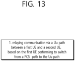
- FIG. 13 shows the procedure of the base station according to disclosure of the present specification.
- the first UE may determine to maintain a unicast link for the PC5 path after the first UE performed to switch from the PC5 path to the Uu path.
- the first UE may determine to switch back to the PC5 path, based on a PC5 signal level of the unicast link.
- a UE may include a processor, a transceiver, and a memory.
- a processor may be configured to be operably coupled with a memory and a processor.
- the processor may perform: communicating with another UE through a PC5 path; switching from the PC5 path to a Uu path; determining to maintain a unicast link for the PC5 path; and determining, on the basis of PC5 signal strength of the unicast link, to switch back to the PC5 path.
- the processor is configured to: communicating with another UE through a PC5 path; switching from the PC5 path to a Uu path; determining to maintain a unicast link for the PC5 path; and determining, on the basis of PC5 signal strength of the unicast link, to switch back to the PC5 path.
- non-volatile computer readable medium storing one or more instructions for providing multicast service in wireless communication according to some embodiments of the present specification will be described.
- the technical features of the present disclosure may be directly implemented as hardware, software executed by a processor, or a combination of the two.
- a method performed by a wireless device may be implemented in hardware, software, firmware, or any combination thereof.
- the software may reside in RAM memory, flash memory, ROM memory, EPROM memory, EEPROM memory, registers, hard disk, removable disk, CD-ROM, or other storage medium.
- a storage medium are coupled to the processor such that the processor can read information from the storage medium.
- the storage medium may be integrated into the processor.
- the processor and storage medium may reside in the ASIC.
- a processor and a storage medium may reside as separate components.
- Computer-readable media can include tangible and non-volatile computer-readable storage media.
- non-volatile computer-readable media may include random access memory (RAM), such as synchronization dynamic random access memory (SDRAM), read-only memory (ROM), or non-volatile random access memory (NVRAM).
- RAM random access memory
- SDRAM synchronization dynamic random access memory
- ROM read-only memory
- NVRAM non-volatile random access memory
- EEPROM Read-only memory
- flash memory magnetic or optical data storage media, or other media that can be used to store instructions or data structures
- Non-volatile computer readable media may also include combinations of the above.
- the methods described herein may be realized at least in part by computer-readable communication media that carry or carry code in the form of instructions or data structures and that can be accessed, read, and/or executed by a computer.
- a non-transitory computer-readable medium has one or more instructions stored thereon.
- the stored one or more instructions may be executed by a processor of the base station.
- the stored one or more instructions cause the processors to: communicating with another UE through a PC5 path; switching from the PC5 path to a Uu path; determining to maintain a unicast link for the PC5 path; and determining, on the basis of PC5 signal strength of the unicast link, to switch back to the PC5 path.
- the present specification may have various effects.
- switching back to the PC5 path can be performed efficiently by reusing the unicast link before switching.
Landscapes
- Engineering & Computer Science (AREA)
- Computer Networks & Wireless Communication (AREA)
- Signal Processing (AREA)
- Computer Security & Cryptography (AREA)
- Mobile Radio Communication Systems (AREA)
Applications Claiming Priority (3)
| Application Number | Priority Date | Filing Date | Title |
|---|---|---|---|
| KR20220032688 | 2022-03-16 | ||
| US202263328254P | 2022-04-06 | 2022-04-06 | |
| PCT/KR2023/003283 WO2023177153A1 (fr) | 2022-03-16 | 2023-03-10 | Procédé de commutation entre uu et pc5 |
Publications (2)
| Publication Number | Publication Date |
|---|---|
| EP4496422A1 true EP4496422A1 (fr) | 2025-01-22 |
| EP4496422A4 EP4496422A4 (fr) | 2026-01-14 |
Family
ID=88023973
Family Applications (1)
| Application Number | Title | Priority Date | Filing Date |
|---|---|---|---|
| EP23771032.2A Pending EP4496422A4 (fr) | 2022-03-16 | 2023-03-10 | Procédé de commutation entre uu et pc5 |
Country Status (4)
| Country | Link |
|---|---|
| US (1) | US20250227783A1 (fr) |
| EP (1) | EP4496422A4 (fr) |
| CN (1) | CN119054411A (fr) |
| WO (1) | WO2023177153A1 (fr) |
Family Cites Families (8)
| Publication number | Priority date | Publication date | Assignee | Title |
|---|---|---|---|---|
| EP3223575B1 (fr) * | 2015-11-19 | 2019-06-12 | ASUSTek Computer Inc. | Procédés et appareil pour commuter une interface de communication dans un système de communications sans fil |
| KR102582554B1 (ko) * | 2017-01-03 | 2023-09-25 | 삼성전자 주식회사 | 차세대 이동 통신 시스템에서 light connection을 지원하는 방법 및 장치 |
| CN110831075B (zh) * | 2018-08-10 | 2024-08-27 | 中兴通讯股份有限公司 | 数据传输方法及装置,业务切换方法及装置 |
| KR20210039200A (ko) * | 2019-10-01 | 2021-04-09 | 삼성전자주식회사 | 무선통신 시스템에서 직접 통신 세션 관리 방법 및 장치 |
| KR102645819B1 (ko) * | 2019-11-07 | 2024-03-07 | 엘지전자 주식회사 | 무선 통신 시스템에서 사이드링크 통신에 관련된 설정을 제어하기 위한 방법 및 장치 |
| US12273782B2 (en) * | 2020-04-02 | 2025-04-08 | Interdigital Patent Holdings, Inc. | Methods, apparatus and systems for command and control (C2) communications setup and update |
| US11856645B2 (en) * | 2020-05-21 | 2023-12-26 | Apple Inc. | Proximity services path selection and switching |
| CN114257970B (zh) * | 2020-09-21 | 2023-05-30 | 华硕电脑股份有限公司 | 无线通信系统中支持用户设备到网络中继通信的方法和设备 |
-
2023
- 2023-03-10 US US18/847,511 patent/US20250227783A1/en active Pending
- 2023-03-10 WO PCT/KR2023/003283 patent/WO2023177153A1/fr not_active Ceased
- 2023-03-10 EP EP23771032.2A patent/EP4496422A4/fr active Pending
- 2023-03-10 CN CN202380034272.0A patent/CN119054411A/zh active Pending
Also Published As
| Publication number | Publication date |
|---|---|
| US20250227783A1 (en) | 2025-07-10 |
| WO2023177153A1 (fr) | 2023-09-21 |
| CN119054411A (zh) | 2024-11-29 |
| EP4496422A4 (fr) | 2026-01-14 |
Similar Documents
| Publication | Publication Date | Title |
|---|---|---|
| US11490351B2 (en) | Efficient PLMN selection upon authentication failure for each network slice in roaming network | |
| EP4322691B1 (fr) | Procédé de gestion de sessions pdu | |
| US12262253B2 (en) | Support of service continuity between SNPN and PLMN | |
| US12470987B2 (en) | N14 interface support indicator for service continuity | |
| US12238812B2 (en) | Support of service continuity for handover between SNPN and PLMN | |
| US11924287B2 (en) | Method for managing session | |
| US20240187887A1 (en) | Method for managing redundant pdu session for redundant transmission | |
| EP4224930B1 (fr) | Support de continuité de service pour une session pdu à routage domestique lorsqu'il n'y a pas d'interface n14 entre un réseau source et un réseau cible | |
| EP4213523A1 (fr) | Procédé d'acceptation d'une politique d'application de sécurité entre une liaison pc5 et une liaison uu dans une communication de relais prose, et dispositif prenant en charge ledit procédé | |
| EP4199586A1 (fr) | Procédé de gestion de session | |
| EP4443949A1 (fr) | Procédé de mesure d'utilisation de trafic | |
| US12526609B2 (en) | Communication method by means of multicast | |
| EP4518566A1 (fr) | Procédé de gestion de communication c2 | |
| EP4568350A1 (fr) | Procédé de gestion de chemins multiples | |
| EP4648487A1 (fr) | Procédé de sélection de noeud non 3gpp | |
| EP4568351A1 (fr) | Procédé de gestion de trajets multiples | |
| EP4297481A1 (fr) | Procédé de communication pour mbs | |
| EP4496422A1 (fr) | Procédé de commutation entre uu et pc5 | |
| EP4694070A1 (fr) | Procédé de mesure de latence | |
| EP4598074A1 (fr) | Procédé de détermination de règle d´ursp | |
| EP4664991A1 (fr) | Procédé de gestion d'easdf | |
| EP4583627A1 (fr) | Procédé de transmission de duplication utilisant un trajet multiple | |
| EP4664965A1 (fr) | Procédé de gestion de nsacf locale | |
| EP4712578A1 (fr) | Procédé de communication snpn | |
| EP4593516A1 (fr) | Procédé de transmission en double utilisant un trajet multiple |
Legal Events
| Date | Code | Title | Description |
|---|---|---|---|
| STAA | Information on the status of an ep patent application or granted ep patent |
Free format text: STATUS: THE INTERNATIONAL PUBLICATION HAS BEEN MADE |
|
| PUAI | Public reference made under article 153(3) epc to a published international application that has entered the european phase |
Free format text: ORIGINAL CODE: 0009012 |
|
| STAA | Information on the status of an ep patent application or granted ep patent |
Free format text: STATUS: REQUEST FOR EXAMINATION WAS MADE |
|
| 17P | Request for examination filed |
Effective date: 20240918 |
|
| AK | Designated contracting states |
Kind code of ref document: A1 Designated state(s): AL AT BE BG CH CY CZ DE DK EE ES FI FR GB GR HR HU IE IS IT LI LT LU LV MC ME MK MT NL NO PL PT RO RS SE SI SK SM TR |
|
| DAV | Request for validation of the european patent (deleted) | ||
| DAX | Request for extension of the european patent (deleted) | ||
| A4 | Supplementary search report drawn up and despatched |
Effective date: 20251217 |
|
| RIC1 | Information provided on ipc code assigned before grant |
Ipc: H04W 76/23 20180101AFI20251211BHEP Ipc: H04W 76/14 20180101ALI20251211BHEP Ipc: H04W 4/40 20180101ALI20251211BHEP Ipc: H04W 92/10 20090101ALI20251211BHEP Ipc: H04W 92/18 20090101ALI20251211BHEP Ipc: H04W 24/10 20090101ALI20251211BHEP Ipc: H04W 36/00 20090101ALI20251211BHEP Ipc: H04W 12/08 20210101ALI20251211BHEP |