EP4496427A2 - Verfahren zur übertragung kleiner datenmengen - Google Patents
Verfahren zur übertragung kleiner datenmengen Download PDFInfo
- Publication number
- EP4496427A2 EP4496427A2 EP24210805.8A EP24210805A EP4496427A2 EP 4496427 A2 EP4496427 A2 EP 4496427A2 EP 24210805 A EP24210805 A EP 24210805A EP 4496427 A2 EP4496427 A2 EP 4496427A2
- Authority
- EP
- European Patent Office
- Prior art keywords
- message
- gnb
- sdt
- context
- receiving
- Prior art date
- Legal status (The legal status is an assumption and is not a legal conclusion. Google has not performed a legal analysis and makes no representation as to the accuracy of the status listed.)
- Pending
Links
Images


Classifications
-
- H—ELECTRICITY
- H04—ELECTRIC COMMUNICATION TECHNIQUE
- H04W—WIRELESS COMMUNICATION NETWORKS
- H04W76/00—Connection management
- H04W76/20—Manipulation of established connections
- H04W76/22—Manipulation of transport tunnels
-
- H—ELECTRICITY
- H04—ELECTRIC COMMUNICATION TECHNIQUE
- H04W—WIRELESS COMMUNICATION NETWORKS
- H04W28/00—Network traffic management; Network resource management
- H04W28/02—Traffic management, e.g. flow control or congestion control
- H04W28/10—Flow control between communication endpoints
- H04W28/12—Flow control between communication endpoints using signalling between network elements
-
- H—ELECTRICITY
- H04—ELECTRIC COMMUNICATION TECHNIQUE
- H04W—WIRELESS COMMUNICATION NETWORKS
- H04W76/00—Connection management
- H04W76/20—Manipulation of established connections
- H04W76/27—Transitions between radio resource control [RRC] states
-
- H—ELECTRICITY
- H04—ELECTRIC COMMUNICATION TECHNIQUE
- H04W—WIRELESS COMMUNICATION NETWORKS
- H04W76/00—Connection management
- H04W76/30—Connection release
Definitions
- This document is directed generally to wireless communications, and in particular to small data transmissions.
- a user equipment When a user equipment (UE) needs to transmit data to the network, the UE may be required to establish a connection with the network (e.g. entering a connected state) no matter what amount of data needs to be transmitted. Under such conditions, huge signal overhead may be wasted on transmissions of small amount of data.
- new radio NR
- NR new radio
- SDT small data transmission
- the network may need to determine whether to relocate UE context to a network node currently serving the UE. If the network cannot immediately determine whether to relocate UE context or decides not to relocate the UE context, the SDT may be performed in a delayed manner or abnormally.
- This document relates to methods, systems, and devices for the SDT, and in particular to methods, systems, and devices for the SDT in a resume procedure.
- the present disclosure relates to a wireless communication method for use in an anchor node.
- the method comprises receiving, from a serving node, a context request associated with a wireless terminal and an indication for a small data transmission, transmitting, to the serving node, a first message comprising configuration information of the small data transmission, receiving, from the serving node, a second message comprising downlink information of the small data transmission, and performing the small data transmission.
- the wireless terminal is in an inactive state or a connection management connected state.
- the small data transmission is characterized by at least one of the following features:
- the small data transmission is defined according to 3GPP TR 25.705 V13.0.0.
- the first message is transmitted and the second message is received no later than transmitting a response message in response to the resume request.
- the response message comprises one of context information of the wireless terminal or a radio resource control release message.
- the first message is transmitted and the second message is received after transmitting a response message in response to the resume request, wherein the response message comprises a radio resource control release message.
- the configuration information comprises at least one of an uplink address of the small data transmission or a radio link control configuration of the small data transmission.
- the performing the small data transmission comprises receiving, from a user plane function, downlink data of the wireless terminal, and transmitting, to the serving node, the downlink data.
- the present disclosure relates to wireless communication method for use in a serving node.
- the method comprises:
- the wireless terminal is in an inactive state or a connection management connected state.
- the small data transmission is defined according to 3GPP TR 25.705 V13.0.0.
- the first message is received and the second message is transmitted no later than receiving a response message in response to the resume request.
- the response message comprises one of context information of the wireless terminal or a radio resource control release message.
- the first message is received and the second message is transmitted after receiving a response message in response to the resume request, wherein the response message comprises a radio resource control release message.
- the configuration information comprises at least one of an uplink address of the small data transmission or a radio link control configuration of the small data transmission.
- the downlink information comprises a downlink cell group transport network layer address.
- the wireless communication method further comprises establishing radio link control entities for the small data transmission based on the configuration information, or determining an uplink address of the small data transmission based on the configuration information.
- the performing the small data transmission comprises receiving, from the anchor node, downlink data of the wireless terminal, and transmitting, to the wireless terminal, the downlink data.
- the performing the small data transmission comprises receiving, from the wireless terminal, uplink data, and transmitting, to the anchor node, the uplink data.
- the present disclosure relates to an anchor node.
- the anchor node comprises: a communication unit, configured to:
- the processor is further configured to perform any one of aforementioned wireless communication method.
- the present disclosure relates to a serving node.
- the serving node comprises: a communication unit, configured to:
- the processor is further configured to perform any one of aforementioned wireless communication method.
- the present disclosure relates to a computer program product comprising a computer-readable program medium code stored thereupon, the code, when executed by a processor, causing the processor to implement a wireless communication method recited in any one of foregoing methods.
- the present disclosure is not limited to the exemplary embodiments and applications described and illustrated herein. Additionally, the specific order and/or hierarchy of steps in the methods disclosed herein are merely exemplary approaches. Based upon design preferences, the specific order or hierarchy of steps of the disclosed methods or processes can be re-arranged while remaining within the scope of the present disclosure. Thus, those of ordinary skill in the art will understand that the methods and techniques disclosed herein present various steps or acts in a sample order, and the present disclosure is not limited to the specific order or hierarchy presented unless expressly stated otherwise.
- a small data transmission may be a data transmission performed for (or by) the UE in an inactive state (e.g. radio resource control (RRC) inactive state (RRC_INACTIVE)) or a connection management (CM) connected (CM-CONNECTED) state.
- RRC radio resource control
- CM connection management
- the SDT may be performed in a random access procedure or a(n) (RRC) resume procedure.
- fundamental characteristics of the SDT may comprise at least one of:
- the latency of the SDT is a duration from the packet of the SDT arriving at the buffer until the packet is completely transmitted.
- the small data transmission is further specified in 3GPP TR 25.705 V13.0.0.
- FIG. 1 relates to an RRC resume procedure with anchor relocation according to an embodiment of the present disclosure.
- the UE context is transferred from an anchor gNB (e.g. the last serving gNB) to a current serving gNB (e.g. receiving gNB), a path switch procedure is performed after the UE context is fetched and the serving gNB becomes the new anchor gNB after the anchor relocation (e.g. the relocation of the UE context).
- an anchor gNB e.g. the last serving gNB
- a current serving gNB e.g. receiving gNB
- a path switch procedure is performed after the UE context is fetched and the serving gNB becomes the new anchor gNB after the anchor relocation (e.g. the relocation of the UE context).
- the gNB may be equal to a wireless network node, a radio access network (RAN) node, a next generation (NG) RAN node, an evolved Node B (eNB), or an NG-eNB.
- RAN radio access network
- NG next generation
- eNB evolved Node B
- the UE is in an inactive state (e.g. RRC INACTIVE) and/or in the CM-CONNECTED state.
- the UE resumes from the inactive state and sends an RRC resume request (message) to a gNB (e.g. serving gNB or receiving gNB), for providing an inactive identifier (e.g. inactive radio network temporary identifier (I-RNTI)) allocated by the last serving gNB and a cause value.
- the cause value indicates a cause (e.g. reason, purpose) of sending the RRC resume request.
- the cause value may indicate an RAN notification area (RNA) update (step 101).
- RNA RAN notification area
- the gNB if able to resolve an identity (e.g. associated with the last serving gNB) contained in the inactive identifier, requests the last serving gNB to provide UE context, e.g. by providing the cause value received in step 101.
- an identity e.g. associated with the last serving gNB
- step 103 the last serving gNB provides the UE context in a response message (e.g. RETRIEVE UE CONTEXT RESPONSE).
- a response message e.g. RETRIEVE UE CONTEXT RESPONSE
- step 104 the gNB transmits an RRC resume message to keep the UE in the inactive state.
- step 105 the UE transmits an RRC resume complete message to the gNB.
- step 106 if loss of downlink (DL) user data buffered in the last serving gNB shall be prevented, the gNB provides forwarding addresses to the last serving gNB.
- DL downlink
- the gNB performs a path switch procedure with an access and mobility management function (AMF).
- AMF access and mobility management function
- step 109 the gNB triggers a release of the UE resources at the last serving gNB.
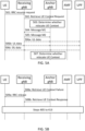
- FIG. 2 relates to an RRC resume procedure without the anchor relocation according to an embodiment of the present disclosure. Note that, the RRC resume procedure without the anchor relocation may only be used for the RNA update.
- the inactive state e.g. RRC_INACTIVE
- the appropriate cause value e.g., indicating the RNA update
- step 202 the gNB, if able to determine the gNB identity contained in the I-RNTI, requests the last serving gNB to provide the UE context by providing the cause value received in step 201.
- the last serving gNB stores the received information to be used in the next resume attempt (e.g. cell RNTI (C-RNTI) and physical cell identifier (PCI) related to a resumption cell), and responds to the gNB with the a failure message (e.g. RETRIEVE UE CONTEXT FAILURE message) including an encapsulated RRC release message.
- the RRC release message includes a suspend indication.
- the serving gNB may not be able to identify the anchor gNB based on the short I-RNTI, the serving gNB may send the context request message (e.g. Retrieve UE Context Request message) to multiple potential anchor gNBs.
- the context request message e.g. retrieve UE Context Request message
- the context request message can only be verified by the corresponding anchor gNB and only the anchor gNB has the UE context, it is up to the anchor gNB to determine whether the anchor relocation (i.e. the relocation of the UE context) is needed or not.
- the RRC resume procedure without anchor relocation can only be applied for the RNA update. That is, the SDT may be delayed or may not be performed during the RRC resume procedure without the anchor relocation.
- the receiving gNB may be equal to a receiving node and/or the gNB shown in FIGS. 1 and 2 .
- the anchor gNB may be equal to an anchor node and/or the last serving gNB shown in FIGS. 1 and 2 .
- uplink (UL) data in the following paragraphs is UL data for the SDT and DL data in the following paragraphs is DL data for the SDT.
- FIG. 3 shows a schematic diagram of a signaling procedure according to an embodiment of the present disclosure.
- the receiving gNB transmits a context request message (e.g. "Retrieve UE Context Request" message) for the UE context to the anchor gNB.
- the context request message is associated with the SDT.
- the context request message may include (e.g. indicate) a cause or a cause value associated with the SDT.
- the cause or the cause value may be (associated with) an SDT indicator or multiple-SDT indicator.
- the anchor gNB determines (e.g. decides) whether to relocate the UE context to the receiving gNB. In this embodiment, the anchor gNB may determine whether to relocate the UE context in a later stage. As an alternative or in addition, the anchor gNB may determine not to relocate the UE context.
- the anchor gNB determines whether to relocate the UE context in the later stage or the anchor gNB determining not to relocate the UE context, the anchor gNB performs (e.g. initiate) a signaling procedure with the receiving gNB (i.e. steps 303-1 and 303-2).
- the signaling procedure is initiated by the anchor gNB and is used to establish tunnel(s) between the anchor gNB and the received gNB.
- the anchor gNB may establish UE radio link control (RLC) context at the receiving gNB and to configure UL/DL transport network layer (TNL) address(es) between the receiving gNB and the anchor gNB for the UL/DL data transmissions (e.g. UL/DL packet data convergence protocol (PDCP) packet data unit (PDU) packet transmissions).
- RLC radio link control
- TNL transport network layer
- the signaling procedure may be named SDT RLC context transfer procedure or SDT RLC entity establish procedure.
- the anchor gNB when anchor gNB initiates the signaling procedure, the anchor gNB firstly sends a message M1 (e.g. SDT RLC context transfer request (message) or SDT RLC entity establish request (message)) to the receiving gNB.
- a message M1 e.g. SDT RLC context transfer request (message) or SDT RLC entity establish request (message)
- M2 e.g., SDT RLC context transfer response, or SDT RLC entity establish response
- the message M1 includes at least one of the following information (the information may be named RLC context for the SDT):
- the message M2 includes DL cell group (CG) TNL address for the SDT.
- the receiving gNB may perform at least one of the following actions:
- the anchor gNB may execute at least one of the following actions:
- the receiving gNB After completing the signaling procedure, the receiving gNB is able to transmit the UL data or receive the DL data via the anchor gNB. For example, the receiving gNB may perform at least one of steps 304a, 304b and 304c.
- step 304a the receiving gNB transmits the UL data of the UE to the anchor gNB or the user plane function (UPF) via the anchor gNB, wherein the UL data may be received and buffered before the signaling procedure (e.g. in step 301) completes.
- the signaling procedure e.g. in step 301
- the receiving gNB receives the UL data for the SDT (e.g. PDU packets) from the UE and transmits the received UL data (e.g. PDCP PDU packets, or RLC SDU packets) for the SDT to the anchor gNB or the UPF via the anchor gNB.
- the UL data for the SDT e.g. PDU packets
- the received UL data e.g. PDCP PDU packets, or RLC SDU packets
- the receiving gNB receives the DL data (e.g. PDCP PDU packets, or RLC SDU packets) for the SDT from the anchor gNB or the UPF via the anchor gNB and transmits the received DL data to the UE.
- the DL data e.g. PDCP PDU packets, or RLC SDU packets
- the anchor gNB after the anchor gNB receiving the context request message (e.g. Retrieve UE context Request message) associated with the SDT from the receiving gNB, the anchor gNB will decide whether and when to relocate the UE context.
- the anchor gNB may have the following options:
- FIGS. 4A and 4B show a schematic diagram of an RRC resume procedure according to an embodiment of the present disclosure.
- the anchor gNB may decide to immediately relocate the UE context (i.e. the above Option 1) after receiving the context request message from the receiving gNB.
- the UE in the inactive state transmits an RRC message (e.g. RRC Resume Request message) to the receiving gNB (step 401 in FIG. 4A ).
- the UE may transmit UL data of the SDT along with this RRC message and the transmitted UL data is buffered by the receiving gNB.
- the receiving gNB sends a context request message (e.g. "Retrieve UE Context request" message) including the SDT indicator to the anchor gNB.
- a context request message e.g. "Retrieve UE Context request” message
- the context request message may further include a DL CG TNL address for the SDT to anchor gNB
- step 403 the anchor gNB decides to relocate UE context.
- the anchor gNB sends a context response message (e.g. "Retrieve UE Context response" message) including the UE context to the receiving gNB.
- a context response message e.g. "Retrieve UE Context response" message
- step 405 the receiving gNB sends an Xn-U address indication message to the anchor gNB (Optional).
- step 406 the receiving gNB acquires the UE context and establishes RLC entities and PDCP entities based on the UE context.
- the receiving gNB may optionally perform steps 407a and/or 407b and/or 407c before initiating a path switch procedure.
- step 407a the receiving gNB transmits buffered UL data (e.g. the UL data received in Step 402), if any, to the UPF via the anchor gNB.
- buffered UL data e.g. the UL data received in Step 402
- step 407b the receiving gNB transmits subsequent UL data to the UPF via the anchor gNB when receiving the subsequent UL data from the UE.
- the receiving gNB transmits DL data (i.e., DL RLC SDU) to the UE if receiving the DL data from the UPF via the anchor gNB.
- DL data i.e., DL RLC SDU
- the receiving gNB initiates the path switch procedure with the core network (e.g., 5G core network (5GC) or the AMF (i.e. one 5GC entity)).
- the core network e.g., 5G core network (5GC) or the AMF (i.e. one 5GC entity)
- the receiving gNB may transmit buffered UL data, if any, (step 409a) and/or transmit the UL data to the UPF when receiving the UL data from the UE (step 409b), and/or send DL data to the UE when receiving the DL data from the UPF (step 409c).
- the receiving gNB may determine to send the UE to one of the RRC connected state, the RRC inactive state or the idle state.
- the receiving gNB determines sending the UE to the RRC connected state
- the receiving gNB transmits an RRC resume message (step 411) and the UE feedbacks an RRC resume complete message (step 412).
- the UE enters in the RRC connected state after the steps 411 and 412.
- the receiving gNB If determining sending the UE to the RRC inactive state, the receiving gNB sends an RRC release message with a suspend indication (step 413). After receiving the RRC release message, the UE enters to the RRC inactive state.
- FIGS. 5A and 5B show a schematic diagram of a resume procedure according to an embodiment of the present disclosure.
- the anchor gNB may decide to determine whether to relocate the UE context in the later stage or not to relocate the UE context (i.e. the above Options 2 and 3) after receiving the context request message from the receiving gNB.
- the UE in the inactive state transmits an RRC message (e.g. RRC Resume Request message) to the receiving gNB (step 501 in FIG. 5A ).
- the UE may transmit UL data of the SDT along with this RRC message and the transmitted UL data is buffered by the receiving gNB.
- the receiving gNB sends a context request message (e.g. "Retrieve UE Context request" message) including the SDT indicator to the anchor gNB.
- a context request message e.g. "Retrieve UE Context request” message
- the context request message may further include a DL CG TNL address for the SDT to the anchor gNB
- the anchor gNB decides to determine whether to relocate the UE context in the later stage. As an alternative, the anchor gNB decides not to relocate the UE context and transmits the Retrieve UE context Failure message to the receiving gNB.
- the anchor gNB performs the signaling procedure between the anchor gNB and the receiving gNB when deciding not to relocate the UE context or deciding to determine whether to relocate the UE context in the later stage.
- the anchor gNB firstly sends a message M1 (e.g. request message) to receiving gNB, wherein the message M1 includes the RLC configuration (e.g. for SDT) and/or the UL PDCP TNL address (e.g. for SDT) (step 504).
- the receiving gNB sends a message M2 (e.g. response message) to the anchor gNB, wherein the message M2 includes the DL CG TNL address (e.g. for SDT).
- the receiving gNB may perform at least one of the following actions:
- the anchor gNB may perform at least one of the following actions after the signaling procedure completes:
- the UL data and/or the DL data may be transmitted and/or received in PDCP PDU packets, which is also called RLC SDU, between the receiving gNB and the anchor gNB.
- PDCP PDU packets which is also called RLC SDU
- the anchor gNB may determine whether to relocate the UE context in step 507.
- the anchor gNB decides not to relocate the UE context in step 507 and sends the Retrieve UE context Failure message to the receiving gNB, wherein the Retrieve UE context Failure message comprises RRC release message (step 508a).
- the receiving gNB then transmits the RRC release message to the UE, to instruct the UE to enter the inactive state (step 509a).
- the anchor gNB determines not to relocate the UE context in step 503
- the anchor gNB and the receiving gNB would perform steps 504 to 506c and the receiving gNB may transmit the RRC release message (step 509a) after determining that there is not subsequent UL/DL data from the UE.
- the Retrieve UE context Failure message including the RRC release message may be sent before step 509a and/or after step 503.
- the anchor gNB determines to relocate the UE context in step 507, the anchor gNB transmits the Retrieve UE context response message including the UE context to the receiving gNB (step 508b).
- the procedure following step 508b can be referred to steps 405 to 413 shown in FIG. 4 .
- FIGS. 6A, 6B , 6C and 6D show a flowchart of a resume procedure according to an embodiment of the present disclosure.
- the procedure shown in FIGS. 6A, 6B , 6C and 6D may be used in a receiving gNB (e.g. that shown in FIGS. 4A, 4B , 5A and 5B ) and comprises the following steps.
- the receiving gNB receives an RRC Resume Request message from the UE.
- the receiving gNB may also receive UL data of the SDT from the UE in step 601.
- the receiving gNB sends a Retrieve UE Context request message to an anchor gNB.
- the Retrieve UE Context request message includes an SDT indictor, and optionally includes the SDT DL CG TNL address.
- step 603-1 if the receiving gNB receives, a Retrieve UE Context Response message, from the anchor gNB, step 604a shown in FIG. 6B would be performed; otherwise step 603-2 is performed.
- step 603-2 if a signaling message (e.g. message M1) is received, step 604b is performed.
- step 604c is performed.
- step 604a the receiving gNB acquires UE context (e.g. in the Retrieve UE Context Response message), establishes radio link control (RLC) entities and PDCP entities, optionally acquires SDT UL PDCP TNL address.
- UE context e.g. in the Retrieve UE Context Response message
- RLC radio link control
- PDCP entities optionally acquires SDT UL PDCP TNL address.
- step 605a is performed.
- the receiving gNB transmits (buffered) UL data, if any, to the UPF and/or receives DL data, if any, from anchor gNB and transmits the received DL data to the UE.
- the UL data sent to the UPF is in UL SDT PDU packets.
- the DL data received from the anchor gNB is in DL SDT PDCP PDU packets.
- the DL data sent to the UE is in DL SDT PDU packets.
- step 606a the receiving gNB initiate the path switch procedure (e.g. with the AMF).
- the receiving gNB receives subsequent UL data from the UE, if any, and transmits buffered UL data, if any, and the subsequent UL data, if any, to the UPF. In addition, the receiving gNB receives subsequent DL data from the UPF, if any, and transmits the received subsequent data to the UE.
- step 608a the receiving gNB sends the UE to one of the RRC connected state, the RRC inactive state or the RRC idle state. The procedure ends after step 608a.
- the receiving gNB acquires the RLC context (at least for the SDT), establishes RLC entities (at least for SDT usage) based on the received signaling message (i.e. the message M1) and sends a message M2 to the anchor gNB, wherein the message M2 includes SDT DL CG TNL address(es).
- the RLC context includes the RLC configuration and the UL SDT TNL address(es).
- the receiving gNB transmits the UL data, if any, to the anchor gNB.
- the receiving gNB receives the DL data from the anchor gNB, if any, and transmits the received DL data to UE.
- both the UL data and DL data are in the PDCP PDU packets.
- the UL data includes buffered UL data (e.g. that receiving in step 601, if any) and/or subsequence UL data received from UE after step 604b.
- step 606b if the receiving gNB receives the Retrieve UE Context Response message from the anchor gNB, step 604a is performed. In addition, if the receiving gNB receives the Retrieve UE Context Failure message, step 607b is performed.
- the receiving gNB receives subsequent UL data, if any, from the UE and transmits the received subsequent UL data to the UPF.
- the receiving gNB receives subsequence DL data, if any, from the anchor gNB and transmits the received subsequent DL data to the UE.
- the UL data from the UE is in UL PDU packets and the UL data to UPF is in UL PDCP PDU packets.
- the DL data from the anchor gNB is in DL PDCP PDU packets.
- step 608b the receiving gNB sends the UE to the RRC inactive state or the RRC idle state. The procedure ends after the step 608b.
- step 604c of FIG. 6D the receiving gNB receives the signaling message (i.e. message M1) from the anchor gNB.
- the receiving gNB sends the message 2 to the anchor gNB.
- the receiving gNB acquires RLC context (at least for the SDT) and establishes RLC entities (at least for the SDT) based on the signaling message, wherein the RLC context includes the RLC configuration and the UL SDT TNL address.
- step 606c the receiving gNB transmits UL data, if any, to the anchor gNB.
- the receiving gNB receives DL data from the anchor gNB, if any, and transmits the received DL data to the UE. Details of steps 605c and 606c may be referred to those of step 604b and 605b.
- step 607c the receiving gNB determines whether there is still subsequent UL/DL data. If no, step 608c is performed; otherwise, step 606c is performed.
- Step 608c the receiving gNB sends the UE to the RRC inactive state or the RRC idle state. The procedure ends after this step.
- FIGS. 7A and 7B show a flowchart of a resume procedure according to an embodiment of the present disclosure.
- the procedure shown in FIGS. 7A and 7B may be used in an anchor gNB (e.g. that shown in FIGS. 4A, 4B , 5A and 5B ) and comprises the following steps.
- step 701 of FIG. 7A the anchor gNB receives a Retrieve UE Context request message from the receiving gNB.
- the Retrieve UE Context request message comprises an SDT indicator.
- the Retrieve UE Context request message may include an SDT DL CG TNL address.
- step 702 the anchor node decides whether to relocate the UE context. If the anchor node decides to relocate UE context, step 703a is performed; if deciding not to relocate the UE context, step 703b is performed; if having not decided whether to relocate UE context or not (i.e. decide to determine whether to relocate the UE context later), step 703c is performed.
- the anchor gNB sends the Retrieve UE Context Response message to the receiving gNB, wherein the Retrieve UE Context Response message includes the UE context.
- the Retrieve UE Context Response message may include SDT UL PDCP TNL address.
- the anchor gNB may send DL data received from the UPF, if any, to the receiving gNB.
- the DL data received from the UPF is in PDU packets and the DL data sent to receiving gNB is in DL PDCP PDU packets.
- step 703b of FIG. 7A the anchor gNB sends the Retrieve UE Context Failure message to the receiving gNB, wherein the Retrieve UE Context Failure message includes an RRC release message.
- step 704b the anchor gNB initiates the signaling procedure with receiving gNB. That is, the anchor gNB sends the message M1 to the receiving gNB and receives the message 2 from receiving gNB.
- the anchor gNB receives UL data (i.e., PDCP PDU packets) from the receiving gNB, if any, and transmits the received UL data (i.e., PDU packets) to the UPF.
- the anchor gNB sends DL data (i.e., PDU packets) received from the UPF, if any, and transmits the DL data (i.e., PDCP PDU packets) to the receiving gNB.
- the procedure ends after step 705b.
- the anchor node initiates the signaling procedure with the receiving gNB.
- the signaling procedure comprises sending the message M1 to the receiving gNB and receive the message M2 from the receiving gNB.
- the anchor gNB receives UL data (i.e., PDCP PDU packets) from the receiving gNB, if any, and transmits the received UL data (i.e., PDU packets) to the UPF.
- the anchor gNB sends DL data (i.e., PDU packets) received from the UPF, if any, and transmits the DL data (i.e., PDCP PDU packets) to the receiving gNB.
- step 705c the anchor node decides whether to relocate the UE context again. If yes, step 703a is performed. Note that, in this scenario, step 704a may be omitted if there is not remaining DL data from the UPF. When the anchor node decides not to relocate the UE context, step 706c is performed. As an alternative or in addition, the anchor node determines whether to relocate the UE context in an even later stage in step 705c, step 704c is performed.
- step 706c the anchor gNB sends the Retrieve UE Context failure message to the receiving gNB, wherein the Retrieve UE Context failure message includes the RRC release message.
- step 707c the anchor node receives UL data from the receiving gNB, if any, and transmits the UL data to the UPF.
- the anchor gNB sends DL data received from the UPF, if any, and transmits the DL data to the receiving gNB. The procedure ends after step 707c.
- the anchor node may decide whether to relocate UE context. If the anchor node decides not to relocate UE context or to determine whether to relocate the UE context in a later stage, the anchor node initiates the signaling procedure with the receiving node.
- a new Cause e.g. SDT indicator
- the receiving node acquires SDT RLC configuration and SDT UL PDCP TNL address for the SDT, establishes the SDT RLC entities and sends SDT DL CG TNL address to the anchor node.
- the receiving node is able to transmit SDT UL data (i.e., PDCP PDU packets) to the anchor node.
- the anchor node acquires SDT DL CG TNL address and sends SDT UL PDCP TNL address to the receiving node. After this signaling procedure, the anchor node is able to transmit SDT DL data (i.e., PDCP PDU packets) to the receiving node.
- SDT DL data i.e., PDCP PDU packets
- the small data is transmitted to the network as quick as possible and the latency of the SDT is reduced.
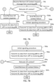
- FIG. 8 shows a flowchart of a process according to an embodiment of the present disclosure.
- the process may be used in an anchor node (e.g. anchor gNB or last serving gNB) and comprises the following steps:
- the anchor node performs the signaling procedure after receiving the context request (message) associated with a wireless terminal (i.e. UE) and an indication of the SDT (e.g. cause value indicating the SDT or an SDT indicator) from the serving node.
- the signaling procedure comprises transmitting a first message (e.g. message M1) comprising configuration information of the SDT to the serving node and receiving a second message (e.g. message M2) comprising DL information (e.g. DL address) of the SDT from the serving node.
- a first message e.g. message M1
- a second message e.g. message M2
- DL information e.g. DL address
- the SDT is the data transmission allowed to be performed for transmitting/receiving small data for the UE in the inactive state.
- the first message is transmitted, and the second message is received no later than transmitting a response message in response to the resume request. That is, the anchor node may not able to determine whether to relocate the UE context (e.g. based on current information) and/or may determine whether to relocate the UE context in a later stage. Or, the anchor node determines not to relocate the UE context in the later stage.
- the response message comprises one of context information (i.e. UE context) of the wireless terminal (i.e. Retrieve UE Context Response message) or an RRC release message (i.e. Retrieve UE Context Failure message).
- the first message is transmitted, and the second message is received after transmitting a response message in response to the resume request, wherein the response message comprises an RRC release message (i.e. Retrieve UE Context Failure message).
- RRC release message i.e. Retrieve UE Context Failure message
- the configuration information comprises at least one of a UL address of the small data transmission (e.g. UL TNL address) or an RLC configuration of the SDT.
- the downlink information comprises a DL CG TNL address.
- the SDT comprises receiving, from a UPF, DL data of the wireless terminal, and transmitting, to the serving node, the downlink data.
- the SDT comprises receiving, from the serving node, UL data of the wireless terminal, and transmitting, to a UPF, the UL data.
- the UL/DL data is small data for the SDT which is allowed to be transmitted/received by the UE in the inactive state (e.g. RRC INACTIVE).
- FIG. 9 shows a flowchart of a process according to an embodiment of the present disclosure.
- the process may be used in a serving node (e.g. receiving gNB) and comprises the following steps:
- the serving node transmits a context request message associated with a wireless terminal and an indication for an SDT to the anchor node.
- the receiving node may receive a resume request from the wireless terminal, determine possible anchor nodes and transmits the context request message to all possible anchor nodes.
- the serving node may receive a first message (e.g. message M1) comprising configuration information of the SDT and transmits a second message (e.g. message M2) comprising DL information of the SDT.
- a first message e.g. message M1
- a second message e.g. message M2
- the serving node is able to perform the SDT, if there is UL/DL data for the SDT.
- the first message is received and the second message is transmitted no later than receiving a response message in response to the resume request. That is, the first message is received and the second message is transmitted before acknowledging that whether anchor relocation is needed.
- the response message comprises one of context information (i.e. UE context) of the wireless terminal (i.e. retrieve UE Context Response message) or an RRC release message (i.e. retrieve UE Context Failure message).
- the first message is received and the second message is transmitted after receiving a response message in response to the resume request, wherein the response message comprises an RRC release message (i.e. Retrieve UE Context Failure message).
- RRC release message i.e. Retrieve UE Context Failure message
- the configuration information comprises at least one of a UL address of the SDT or an RLC configuration of the SDT.
- the configuration information comprises at least one of a UL address of the small data transmission (e.g. UL TNL address) or an RLC configuration of the SDT.
- the DL information comprises a DL CG TNL address.
- the serving node establishes RLC entities for the SDT based on the configuration information and determines (e.g. acquires, accesses) an UL address of the SDT based on the configuration information.
- the SDT comprises receiving, from the anchor node, DL data of the wireless terminal, and transmitting, to the wireless terminal, the DL data.
- the SDT comprises receiving, from the wireless terminal, UL data, and transmitting, to the anchor node, the UL data.
- the UL data may be received from the wireless terminal before step 904 (e.g. in step 901).
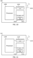
- FIG. 10 relates to a schematic diagram of a wireless terminal 100 according to an embodiment of the present disclosure.
- the wireless terminal 100 may be a user equipment (UE), a mobile phone, a laptop, a tablet computer, an electronic book or a portable computer system and is not limited herein.
- the wireless terminal 100 may include a processor 1000 such as a microprocessor or Application Specific Integrated Circuit (ASIC), a storage unit 1010 and a communication unit 1020.
- the storage unit 1010 may be any data storage device that stores a program code 1012, which is accessed and executed by the processor 1000.
- Embodiments of the storage unit 1012 include but are not limited to a subscriber identity module (SIM), read-only memory (ROM), flash memory, random-access memory (RAM), hard-disk, and optical data storage device.
- SIM subscriber identity module
- ROM read-only memory
- RAM random-access memory
- the communication unit 1020 may a transceiver and is used to transmit and receive signals (e.g. messages or packets) according to processing results of the processor 1000. In an embodiment, the communication unit 1020 transmits and receives the signals via at least one antenna 1022 shown in FIG. 10 .
- the storage unit 1010 and the program code 1012 may be omitted and the processor 1000 may include a storage unit with stored program code.
- the processor 1000 may implement any one of the steps in exemplified embodiments on the wireless terminal 100, e.g., by executing the program code 1012.
- the communication unit 1020 may be a transceiver.
- the communication unit 1020 may as an alternative or in addition be combining a transmitting unit and a receiving unit configured to transmit and to receive, respectively, signals to and from a wireless network node (e.g. a base station).
- a wireless network node e.g. a base station
- FIG. 11 relates to a schematic diagram of a wireless network node 110 according to an embodiment of the present disclosure.
- the wireless network node 110 may be a satellite, a base station (BS), a network entity, a Mobility Management Entity (MME), Serving Gateway (S-GW), Packet Data Network (PDN) Gateway (P-GW), a radio access network (RAN) node, a next generation RAN (NG-RAN), an eNB, an NG-eNB, a gNB, a data network, a core network or a Radio Network Controller (RNC), and is not limited herein.
- MME Mobility Management Entity
- S-GW Serving Gateway
- PDN Packet Data Network Gateway
- RAN radio access network
- NG-RAN next generation RAN
- eNB eNB
- NG-eNB next generation RAN
- gNB next generation RAN
- RNC Radio Network Controller
- the wireless network node 110 may comprise (perform) at least one network function such as an access and mobility management function (AMF), a session management function (SMF), a user place function (UPF), a policy control function (PCF), an application function (AF), etc.
- the wireless network node 110 may include a processor 1100 such as a microprocessor or ASIC, a storage unit 1110 and a communication unit 1120.
- the storage unit 1110 may be any data storage device that stores a program code 1112, which is accessed and executed by the processor 1100. Examples of the storage unit 1112 include but are not limited to a SIM, ROM, flash memory, RAM, hard-disk, and optical data storage device.
- the communication unit 1120 may be a transceiver and is used to transmit and receive signals (e.g. messages or packets) according to processing results of the processor 1100. In an example, the communication unit 1120 transmits and receives the signals via at least one antenna 1122 shown in FIG. 11 .
- the storage unit 1110 and the program code 1112 may be omitted.
- the processor 1100 may include a storage unit with stored program code.
- the processor 1100 may implement any steps described in exemplified embodiments on the wireless network node 110, e.g., via executing the program code 1112.
- the communication unit 1120 may be a transceiver.
- the communication unit 1120 may as an alternative or in addition be combining a transmitting unit and a receiving unit configured to transmit and to receive, respectively, signals to and from a wireless terminal (e.g. a user equipment).
- a wireless terminal e.g. a user equipment
- any reference to an element herein using a designation such as "first,” “second,” and so forth does not generally limit the quantity or order of those elements. Rather, these designations can be used herein as a convenient means of distinguishing between two or more elements or instances of an element. Thus, a reference to first and second elements does not mean that only two elements can be employed, or that the first element must precede the second element in some manner.
- any one of the various illustrative logical blocks, units, processors, means, circuits, methods and functions described in connection with the aspects disclosed herein can be implemented by electronic hardware (e.g., a digital implementation, an analog implementation, or a combination of the two), firmware, various forms of program or design code incorporating instructions (which can be referred to herein, for convenience, as "software” or a "software unit”), or any combination of these techniques.
- a processor, device, component, circuit, structure, machine, unit, etc. can be configured to perform one or more of the functions described herein.
- IC integrated circuit
- DSP digital signal processor
- ASIC application specific integrated circuit
- FPGA field programmable gate array
- the logical blocks, units, and circuits can further include antennas and/or transceivers to communicate with various components within the network or within the device.
- a general purpose processor can be a microprocessor, but in the alternative, the processor can be any conventional processor, controller, or state machine.
- a processor can also be implemented as a combination of computing devices, e.g., a combination of a DSP and a microprocessor, a plurality of microprocessors, one or more microprocessors in conjunction with a DSP core, or any other suitable configuration to perform the functions described herein. If implemented in software, the functions can be stored as one or more instructions or code on a computer-readable medium. Thus, the steps of a method or algorithm disclosed herein can be implemented as software stored on a computer-readable medium.
- Computer-readable media includes both computer storage media and communication media including any medium that can be enabled to transfer a computer program or code from one place to another.
- a storage media can be any available media that can be accessed by a computer.
- such computer-readable media can include RAM, ROM, EEPROM, CD-ROM or other optical disk storage, magnetic disk storage or other magnetic storage devices, or any other medium that can be used to store desired program code in the form of instructions or data structures and that can be accessed by a computer.
- unit refers to software, firmware, hardware, and any combination of these elements for performing the associated functions described herein. Additionally, for purpose of discussion, the various units are described as discrete units; however, as would be apparent to one of ordinary skill in the art, two or more units may be combined to form a single unit that performs the associated functions according embodiments of the present disclosure.
- memory or other storage may be employed in embodiments of the present disclosure.
- memory or other storage may be employed in embodiments of the present disclosure.
- any suitable distribution of functionality between different functional units, processing logic elements or domains may be used without detracting from the present disclosure.
- functionality illustrated to be performed by separate processing logic elements, or controllers may be performed by the same processing logic element, or controller.
- references to specific functional units are only references to a suitable means for providing the described functionality, rather than indicative of a strict logical or physical structure or organization.
Landscapes
- Engineering & Computer Science (AREA)
- Computer Networks & Wireless Communication (AREA)
- Signal Processing (AREA)
- Mobile Radio Communication Systems (AREA)
- Communication Control (AREA)
Priority Applications (1)
| Application Number | Priority Date | Filing Date | Title |
|---|---|---|---|
| EP24210805.8A EP4496427A3 (de) | 2020-12-23 | 2020-12-23 | Verfahren zur übertragung kleiner datenmengen |
Applications Claiming Priority (3)
| Application Number | Priority Date | Filing Date | Title |
|---|---|---|---|
| PCT/CN2020/138478 WO2022133763A1 (en) | 2020-12-23 | 2020-12-23 | A method for small data transmission |
| EP24210805.8A EP4496427A3 (de) | 2020-12-23 | 2020-12-23 | Verfahren zur übertragung kleiner datenmengen |
| EP20966343.4A EP4107907B1 (de) | 2020-12-23 | 2020-12-23 | Verfahren zur übertragung kleiner datenmengen |
Related Parent Applications (1)
| Application Number | Title | Priority Date | Filing Date |
|---|---|---|---|
| EP20966343.4A Division EP4107907B1 (de) | 2020-12-23 | 2020-12-23 | Verfahren zur übertragung kleiner datenmengen |
Publications (2)
| Publication Number | Publication Date |
|---|---|
| EP4496427A2 true EP4496427A2 (de) | 2025-01-22 |
| EP4496427A3 EP4496427A3 (de) | 2025-04-02 |
Family
ID=82158555
Family Applications (2)
| Application Number | Title | Priority Date | Filing Date |
|---|---|---|---|
| EP24210805.8A Pending EP4496427A3 (de) | 2020-12-23 | 2020-12-23 | Verfahren zur übertragung kleiner datenmengen |
| EP20966343.4A Active EP4107907B1 (de) | 2020-12-23 | 2020-12-23 | Verfahren zur übertragung kleiner datenmengen |
Family Applications After (1)
| Application Number | Title | Priority Date | Filing Date |
|---|---|---|---|
| EP20966343.4A Active EP4107907B1 (de) | 2020-12-23 | 2020-12-23 | Verfahren zur übertragung kleiner datenmengen |
Country Status (5)
| Country | Link |
|---|---|
| US (1) | US12557169B2 (de) |
| EP (2) | EP4496427A3 (de) |
| CN (2) | CN116684998A (de) |
| ES (1) | ES2998564T3 (de) |
| WO (1) | WO2022133763A1 (de) |
Families Citing this family (7)
| Publication number | Priority date | Publication date | Assignee | Title |
|---|---|---|---|---|
| KR20220152699A (ko) * | 2021-05-10 | 2022-11-17 | 삼성전자주식회사 | 분리형 기지국에서 단말의 이동성을 고려한 Small Data Transmission을 지원하기 위한 방법 |
| US12568361B2 (en) * | 2022-02-09 | 2026-03-03 | Telefonaktiebolaget Lm Ericsson (Publ) | User equipment, network node and methods in a wireless communications network |
| CN119096691A (zh) * | 2022-04-08 | 2024-12-06 | 谷歌有限责任公司 | 管理空闲移动性中的小数据传输配置参数 |
| CN117796136A (zh) * | 2022-07-25 | 2024-03-29 | 北京小米移动软件有限公司 | 数据传输方法和装置 |
| CN117545065A (zh) * | 2022-07-27 | 2024-02-09 | 大唐移动通信设备有限公司 | 信息传输方法、装置及存储介质 |
| CN118042634A (zh) * | 2022-11-03 | 2024-05-14 | 华为技术有限公司 | 数据传输方法和通信装置 |
| CN121772031A (zh) * | 2024-09-29 | 2026-03-31 | 中兴通讯股份有限公司 | 网络节点、网络架构、信息传输方法、介质及程序产品 |
Family Cites Families (11)
| Publication number | Priority date | Publication date | Assignee | Title |
|---|---|---|---|---|
| CN102752795B (zh) * | 2011-04-20 | 2015-09-30 | 华为终端有限公司 | 数据通信方法和数据通信服务节点 |
| WO2018214052A1 (en) * | 2017-05-24 | 2018-11-29 | Qualcomm Incorporated | Uplink small data transmission in inactive state |
| WO2020087325A1 (en) * | 2018-10-31 | 2020-05-07 | Qualcomm Incorporated | Data transmission with expiration time |
| US12022550B2 (en) * | 2019-03-15 | 2024-06-25 | Lg Electronics Inc. | Small data transmission without path switch procedure |
| CN113475160B (zh) * | 2019-07-04 | 2025-05-13 | Oppo广东移动通信有限公司 | 一种数据传输方法及装置、通信设备 |
| EP4333540A3 (de) * | 2020-05-14 | 2024-06-05 | Koninklijke Philips N.V. | Kleindatenübertragung |
| EP4214956A4 (de) * | 2020-09-15 | 2024-02-21 | NEC Corporation | Verfahren, vorrichtung und computerspeichermedium zur kommunikation |
| KR102646127B1 (ko) * | 2020-09-24 | 2024-03-11 | 오피노 엘엘씨 | 소형 데이터 송신 절차의 릴리스 메시지 |
| EP4229996A1 (de) * | 2020-10-19 | 2023-08-23 | Ofinno, LLC | Uplink-daten eines kleinen datenübertragungsverfahrens |
| EP4128978B1 (de) * | 2020-10-21 | 2026-01-28 | Peninsula Technologies, LLC | Downlink-daten eines kleinen datenübertragungsverfahrens |
| EP3989670B1 (de) * | 2020-10-21 | 2025-12-17 | Nokia Technologies Oy | Anzeige für kleine datenübertragung |
-
2020
- 2020-12-23 ES ES20966343T patent/ES2998564T3/es active Active
- 2020-12-23 CN CN202310497752.2A patent/CN116684998A/zh active Pending
- 2020-12-23 WO PCT/CN2020/138478 patent/WO2022133763A1/en not_active Ceased
- 2020-12-23 EP EP24210805.8A patent/EP4496427A3/de active Pending
- 2020-12-23 CN CN202080097206.4A patent/CN115136724A/zh active Pending
- 2020-12-23 EP EP20966343.4A patent/EP4107907B1/de active Active
-
2023
- 2023-06-23 US US18/340,129 patent/US12557169B2/en active Active
Also Published As
| Publication number | Publication date |
|---|---|
| CN115136724A (zh) | 2022-09-30 |
| CN116684998A (zh) | 2023-09-01 |
| US12557169B2 (en) | 2026-02-17 |
| EP4496427A3 (de) | 2025-04-02 |
| EP4107907B1 (de) | 2024-11-06 |
| ES2998564T3 (en) | 2025-02-20 |
| EP4107907A4 (de) | 2023-11-29 |
| WO2022133763A1 (en) | 2022-06-30 |
| EP4107907A1 (de) | 2022-12-28 |
| US20230337317A1 (en) | 2023-10-19 |
Similar Documents
| Publication | Publication Date | Title |
|---|---|---|
| EP4107907B1 (de) | Verfahren zur übertragung kleiner datenmengen | |
| US20240031253A1 (en) | Method for radio access network visible quality of experience measurement of dual connectivity | |
| US20210022203A1 (en) | Method for deactivating user plane connection and network entity for controlling user plane connection deactivation in network | |
| US20230397291A1 (en) | Method for small data transmission | |
| CN110708720A (zh) | 切换方法、分布单元、终端、集中单元及计算机存储介质 | |
| US20240397357A1 (en) | Service continuity of sidelink relay communication | |
| US20230020986A1 (en) | Method, device and computer program product for wireless communication | |
| US20240107628A1 (en) | Method, device and computer program product for wireless communication | |
| WO2022232999A1 (en) | A method for session management function relocation | |
| US12096277B2 (en) | Method and arrangements for desired buffer size target time | |
| CN111567084A (zh) | 一种切换方法及装置、计算机存储介质 | |
| CN111567085A (zh) | 一种切换方法及装置、计算机存储介质 | |
| CN115643825A (zh) | 用于无线通信的方法、设备和计算机程序产品 | |
| US20240251474A1 (en) | Method for extended drx | |
| CN116458184B (zh) | 一种用于密钥传递的方法 | |
| CN120568409A (zh) | 配置信息发送方法、接收方法、装置及设备 | |
| CN114846843A (zh) | 请求分组数据网络连接信息的通信方法 |
Legal Events
| Date | Code | Title | Description |
|---|---|---|---|
| PUAI | Public reference made under article 153(3) epc to a published international application that has entered the european phase |
Free format text: ORIGINAL CODE: 0009012 |
|
| STAA | Information on the status of an ep patent application or granted ep patent |
Free format text: STATUS: THE APPLICATION HAS BEEN PUBLISHED |
|
| AC | Divisional application: reference to earlier application |
Ref document number: 4107907 Country of ref document: EP Kind code of ref document: P |
|
| AK | Designated contracting states |
Kind code of ref document: A2 Designated state(s): AL AT BE BG CH CY CZ DE DK EE ES FI FR GB GR HR HU IE IS IT LI LT LU LV MC MK MT NL NO PL PT RO RS SE SI SK SM TR |
|
| REG | Reference to a national code |
Ref country code: DE Ref legal event code: R079 Free format text: PREVIOUS MAIN CLASS: H04W0076300000 Ipc: H04W0076270000 |
|
| PUAL | Search report despatched |
Free format text: ORIGINAL CODE: 0009013 |
|
| AK | Designated contracting states |
Kind code of ref document: A3 Designated state(s): AL AT BE BG CH CY CZ DE DK EE ES FI FR GB GR HR HU IE IS IT LI LT LU LV MC MK MT NL NO PL PT RO RS SE SI SK SM TR |
|
| RIC1 | Information provided on ipc code assigned before grant |
Ipc: H04W 76/30 20180101ALN20250224BHEP Ipc: H04W 76/27 20180101AFI20250224BHEP |
|
| STAA | Information on the status of an ep patent application or granted ep patent |
Free format text: STATUS: REQUEST FOR EXAMINATION WAS MADE |
|
| 17P | Request for examination filed |
Effective date: 20250709 |
|
| STAA | Information on the status of an ep patent application or granted ep patent |
Free format text: STATUS: EXAMINATION IS IN PROGRESS |
|
| 17Q | First examination report despatched |
Effective date: 20260309 |