EP4497312A2 - Procédé de détection sans contact de matériau granulaire dans une machine de distribution agricole - Google Patents
Procédé de détection sans contact de matériau granulaire dans une machine de distribution agricole Download PDFInfo
- Publication number
- EP4497312A2 EP4497312A2 EP24219071.8A EP24219071A EP4497312A2 EP 4497312 A2 EP4497312 A2 EP 4497312A2 EP 24219071 A EP24219071 A EP 24219071A EP 4497312 A2 EP4497312 A2 EP 4497312A2
- Authority
- EP
- European Patent Office
- Prior art keywords
- granular material
- transition
- conveyor line
- electronic device
- sensor device
- Prior art date
- Legal status (The legal status is an assumption and is not a legal conclusion. Google has not performed a legal analysis and makes no representation as to the accuracy of the status listed.)
- Granted
Links
Images


Classifications
-
- A—HUMAN NECESSITIES
- A01—AGRICULTURE; FORESTRY; ANIMAL HUSBANDRY; HUNTING; TRAPPING; FISHING
- A01C—PLANTING; SOWING; FERTILISING
- A01C7/00—Sowing
- A01C7/08—Broadcast seeders; Seeders depositing seeds in rows
- A01C7/10—Devices for adjusting the seed-box ; Regulation of machines for depositing quantities at intervals
- A01C7/102—Regulating or controlling the seed rate
- A01C7/105—Seed sensors
-
- A—HUMAN NECESSITIES
- A01—AGRICULTURE; FORESTRY; ANIMAL HUSBANDRY; HUNTING; TRAPPING; FISHING
- A01C—PLANTING; SOWING; FERTILISING
- A01C7/00—Sowing
- A01C7/08—Broadcast seeders; Seeders depositing seeds in rows
- A01C7/10—Devices for adjusting the seed-box ; Regulation of machines for depositing quantities at intervals
- A01C7/107—Calibration of the seed rate
-
- A—HUMAN NECESSITIES
- A01—AGRICULTURE; FORESTRY; ANIMAL HUSBANDRY; HUNTING; TRAPPING; FISHING
- A01C—PLANTING; SOWING; FERTILISING
- A01C7/00—Sowing
- A01C7/20—Parts of seeders for conducting and depositing seed
- A01C7/206—Seed pipes
Definitions
- the invention relates to an electronic device for detecting granular material according to the preamble of patent claim 1, a method for contact-free detection of granular material according to the preamble of patent claim 7 and an agricultural distribution machine for spreading granular material according to the preamble of patent claim 10.
- distribution machines for spreading granular material, in particular seed and/or fertilizer.
- these also include single-seed seed drills, which are suitable for depositing the granular material on an agricultural area.
- distribution machines also have at least one conveyor line, via which the granular material can be fed to at least one downstream spreading device as required or in adjustable quantities.
- Electronic devices for material detection, in particular grain detection, are increasingly being used in distribution machines of this type. These devices are arranged along a conveying and/or dosing section of the distribution machines. Using such electronic devices, the quantity, in particular the number, and/or the distance of the granular material applied and/or deposited, in particular the individual grains, can be recorded and/or determined relatively precisely.
- Such an electronic device for detecting granular material, in particular seed and/or fertilizer is known for example from DE 20 2004 003 702 A1
- the electronic device described here comprises at least one conveying line which, viewed in cross-section, is at least partially round, through which the granular material can be conveyed in adjustable quantities and in a conveying direction by means of pressure difference and/or gravity.
- the electronic device further comprises at least one Sensor device which is designed to detect the granular material, in particular in the form of isolated grains, without contact within a measuring space of the sensor device arranged along the conveyor line.
- One of the problems here is the enlarged area, particularly in the conveying direction immediately behind the edge or the step.
- the enlarged area of the cross-section is not significantly flowed through, at least in sections, by the air carried by the granular material and/or the air flow resulting from the pressure difference. This results in a kind of separation of the flow and/or a dead zone within which dirt, in particular very fine particles, can continue to accumulate and affect the electronic device, in particular the sensor device.
- the object underlying the invention is therefore to design an electronic device for detecting granular material within an agricultural distribution machine in such a way that the operational reliability of such electronic devices is further improved using particularly simple means and/or the precision and/or reliability of the detection is at least almost maintained with increasing operating time.
- the disadvantages of the described prior art are to be at least partially eliminated.
- solids refers to material conveyed by the electronic device, in particular the conveying line, in the form of granular material to be spread, in particular seed and/or fertilizer, and/or contaminants, in particular dust and/or dirt particles.
- this can also be understood to mean liquids conveyed or transported by the electronic device, in particular the conveying line, for example in the form of water particles, and/or dressing, in particular seed dressing.
- both the air or air flow and the solids can be diverted in the conveying direction in front of the measuring chamber, in particular directly in front of the sensor device.
- the multiphase flow resulting from the solids and the air within the electronic device is thus diverted within the transition at least partially, preferably directly, in front of the measuring chamber in the direction of a center point of a radius of curvature of the curved section of the conveying line.
- the multiphase flow in the area of an inner wall of the conveying line is influenced.
- the The flight path of the solids and/or the air is changed in a direction away from the inner wall.
- the conveyor line is oval in the conveying direction before the transition, at least in sections.
- the oval design has decisive advantages in guiding the multiphase flow, in particular the solids, which surprisingly results in a "calming" of the multiphase flow, in particular the conveyed solids.
- the cross-section of the conveyor line is at least almost round.
- the essentially round shape allows a particularly simple and precise alignment of the sensor device, in particular individual sensor elements assigned to one another, which is particularly advantageous for reliable and/or precise detection of the granular material.
- the sensor device is particularly preferably designed in the manner of an optical sensor, in particular an infrared or radar sensor, and is designed to detect the granular material, in particular in the form of isolated grains, in a contact-free or non-contact manner. Furthermore, in a preferred sensor device designed in the manner of an infrared sensor, a plurality of sensor elements, which are designed in particular in the manner of light-emitting diodes, are assigned to one another and/or arranged in alignment in the circumferential direction around the conveyor line.
- an outer and inner inner wall of the conveyor line in the area of the transition, in particular at the transition, has an unequal radius of curvature.
- the inner wall of the conveyor line is formed by the inner surfaces or walls of the conveyor line that can be brought into contact with the multiphase flow, in particular with the solids.
- the outer inner wall is on a center of the The inner inner wall is arranged on the side of the conveyor line facing away from the radius of curvature, while the inner inner wall is consequently arranged on a side of the conveyor line facing the center of the radius of curvature.
- the radius of curvature of the outer inner wall is preferably smaller than the radius of curvature of the inner inner wall.
- the radius of curvature can also be at least almost the same, with the respective centers of the radii of curvature being offset from one another.
- the center of the radius of curvature of the outer inner wall is offset towards the conveyor line.
- the curvature of the outer inner wall is more pronounced than that of the inner inner wall, at least within the transition.
- the inner inner wall is preferably essentially linear, in particular curvature-free, in the region of the transition, while the outer inner wall forms a type of, in particular curved, ramp to the interior of the conveyor line.
- the conveying line, in particular the outer inner wall forms a type of overshoot in the conveying direction in front of the measuring chamber, in particular the sensor device.
- a cross-flow results which is directed with respect to the actual conveying direction of the granular material and which is designed to convey and/or redirect the solids and/or the air at least partially towards an interior of the conveying line, in particular the cross-section.
- the transition is at least almost step-like or seamless.
- the transition from the at least essentially oval to the round cross-section of the conveyor line is at least almost step-like and/or seamless.
- the transition in particular the area of the conveyor line immediately in front of the measuring chamber and/or the sensor device, is at least almost free of edges and/or steps.
- the cross section tapers in the conveying direction at the transition.
- the transition is preferably designed in the manner of a nozzle. This has an at least local acceleration or nozzle effect of the air carried and/or conveyed in the area of the transition. The resulting particularly high speeds of the air and/or the solids achieve a kind of self-cleaning effect of the inner walls and/or the sensor device.
- the conveyor line has at least one course that adjoins the, in particular curved, transition and is at least partially linear, in particular curvature-free, with the measuring space preferably being arranged within the linear, in particular curvature-free, course.
- the linear section is particularly preferably at least almost completely round.
- the sensor device can thus be particularly well attached to the, preferably particularly short, linear or at least almost curvature-free section of the conveyor line.
- the majority of the sensor elements assigned to and/or aligned with one another can thus be particularly easily attached to the conveyor line. The reliability and/or precision of the material and/or grain detection is thus increased in a particularly simple manner.
- At least one first flattening is formed on the conveyor line, in particular on the inner and/or outer inner wall, along the at least one oval and/or round cross section.
- the at least partially circular and/or circular arc-shaped geometry of the conveyor line, in particular of the cross section has at least one linear, in particular at least almost non-curved, wall when viewed in cross section.
- Such flattenings and/or cross sections represent a particularly aerodynamic shape for the conveyed air and/or the solids.
- Particularly preferred is at least one second flattening on the conveyor line, in particular on the inner and/or outer Inner wall.
- the at least one second flattened area is preferably mirror-symmetrical to the at least one first flattened area.
- a device according to the invention is preferred in which the device, in particular the conveyor line, is at least partially made of an at least almost wear-resistant, in particular metallic, material in the conveying direction upstream of the measuring chamber.
- the conveyor line is made of the at least almost wear-resistant material, preferably metal, at an inlet opening and/or at the curved section of the conveyor line.
- a glass fiber reinforced and/or at least partially coated plastic material is also conceivable.
- the contact with the solids places particularly high stress on the areas of the inlet opening and/or the curved section of the conveyor line, as a result of which this preferred embodiment achieves a particularly high level of operational reliability compared to conventional embodiments.
- the at least almost wear-resistant material can also be arranged at least partially from the outside on the conveyor line, in particular in the manner of an insert on the inlet opening.
- the wear-resistant material is preferably connected to the conveyor line in a form-fitting, force-fitting and/or material-fitting manner, with an at least partially glued-in variant being particularly preferred.
- the wear-resistant material arranged at least partially from the outside increases the impact resistance of the conveyor line in this area, in particular against external influences, thereby achieving an even higher operational reliability of the electronic device.
- the object underlying the invention is also achieved by a method of the type mentioned at the beginning.
- the granular material in particular seed and/or fertilizer, is processed by means of a, in particular producible, Pressure difference and/or by gravity through an electronic device with at least one sensor device.
- the granular material in particular the individual grains, is detected by means of the at least one sensor device, wherein the sensor device is designed to generate a sensor signal depending on the detected material and on the basis of a sensitivity or sensitivity that can be set for the sensor device.
- An actual frequency at which the granular material passes through the electronic device, in particular the sensor device is then determined on the basis of the sensor signal.
- the method according to the invention is characterized in that the determined actual frequency is compared with a retrievable and/or predeterminable target frequency with which the granular material is conveyed through the electronic device. In this case, a deviation between the actual frequency and the target frequency is also determined. The sensor signal and/or the sensitivity is then adjusted until a predeterminable acceptance range for the deviation is reached.
- signal changes caused by accumulations of solids, in particular dirt, in the area of the electronic device, in particular the sensor device are at least partially, preferably at least almost completely, compensated.
- the sensor signal and/or the sensitivity are adjusted automatically or automatically by a control and/or regulating system assigned to the electronic device and/or the distribution machine.
- the sensitivity or sensitivity represents a, in particular minimum, measure or threshold of a signal level or signal deflection of the sensor signal at which a granular material guided past the sensor device is detected by the electronic device, in particular the sensor device.
- the sensitivity or sensitivity represents a, in particular minimum, measure or threshold of a signal level or signal deflection of the sensor signal at which a granular material guided past the sensor device is detected by the electronic device, in particular the sensor device.
- the method according to the invention is preferably carried out within a regular, in particular daily and/or annual, calibration process. Alternatively or additionally, such a calibration process can also be carried out during an interruption of the application process and/or before the start of application.
- the target frequency is preferably determined and/or specified on the basis of at least one environmental condition, the granular material to be applied and/or the operating state of the distribution machine. Alternatively or additionally, the target frequency is determined and/or adjusted within a model test. In such a model test, the target frequency can be determined and/or determined using model or test materials, such as steel, wooden bodies or the like, instead of the material to be applied. Furthermore, the target frequency is determined and/or retrieved on the basis of at least one stored function curve.
- the sensor signal is adjusted by means of a variably adjustable electronic signal amplification.
- the sensor signal is automatically increased or reduced accordingly until the actual frequency at least almost reaches the target frequency, in particular within the acceptance range.
- the signal amplification is preferably designed in the manner of an electronic "magnifying glass” that can be adjusted in steps.
- the signal level or signal deflection of the sensor signal, in particular generated by the sensor device is lower at a low signal amplification or level than at a high signal amplification or level. The actual signal level or deflection of the sensor signal generated due to a detected material can thus be increased many times over, in particular depending on the level set.
- an adaptable electrical power supply is preferably provided for the at least one sensor device, wherein a brightness of a light source assigned to the sensor device is used for Detection of the granular material is adjustable depending on the power supply.
- the light source can alternatively or additionally be part of a sensor element designed as a light-emitting diode.
- the electrical power supply is automatically increased or reduced until the acceptance range for the deviation is reached.
- a darkening of the measuring space due to accumulations of solids in the area of the sensor device, in particular the light source is thus compensated by increasing the power supply of the at least one light source, in particular the electrical power.
- a sensor signal that changes compared to an initial state of the sensor signal with increasing operating time, in particular contamination can thus be adjusted by changing the power supply in the direction of the initial state.
- the power supply, in particular the electrical power, for the sensor device, in particular the light source is increased.
- the electronic device is designed according to at least one of the aforementioned embodiments of the electronic device according to the invention for detecting the granular material within the agricultural distribution machine.
- the object underlying the invention is further achieved by an agricultural distribution machine, in particular a sowing machine, of the type mentioned at the outset, wherein the distribution machine, in particular a control and/or regulating system assigned to the distribution machine, is designed to carry out the method according to the invention according to at least one of the aforementioned embodiments.
- the electronic device for detecting the granular material is designed according to at least one of the aforementioned embodiments of the inventive electronic device for detecting the granular material.
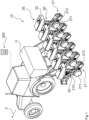
- the distribution machine 10 has at least one storage tank 11 and a frame aligned horizontally transversely to the direction of travel F.
- Several sowing units 20 are attached to the frame by means of support elements.
- Each sowing unit 20 has a storage container 22 for storing the granular or grainy material G to be spread.
- the lower area of the storage container 22 is designed as an outlet area in which at least one outlet opening is arranged.
- the material G to be spread is fed via the outlet opening to a metering device 30 designed as a singling device, which is arranged below the storage container 22.
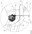
- the dosing device 30, in enlarged sectional view in Fig.2A can be seen, is designed in the manner of an overpressure separator and is set up to dose the material G to be supplied as required and/or in adjustable quantities, in particular in the form of isolated grains.
- a separating element 31 which can be driven in rotation about an axis of rotation and is in particular at least partially rotationally symmetrical is arranged within the dosing device 30.
- the separating element 31 is here at least partially designed as a circular disk.
- the separating element 31 can also be at least partially designed like a drum or cylinder.
- the dosing device 30 can alternatively also be designed as a vacuum separator.
- the granular material G can be conveyed at least partially by gravity from the storage container 31 and/or through the dosing device 30.
- the granular material G is transported and/or carried at least partially in a direction of rotation by the separating element 31 and dispensed and/or transferred to an electronic device 40 arranged downstream and/or on the dosing device 30.
- the granular material G is then conveyed by the electronic device 40 and transferred to a dispensing element 21 at a defined position.
- the spreading member 21 comprises furrow opening elements 210 designed as disc coulters, depth control elements 211 and devices 212 for closing a furrow.
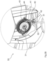
- the electronic device 40 shown in a closer view is designed in the manner of an opto-transmitter and is set up to detect the material G conveyed by the agricultural distribution machine 10.
- the electronic device 40 comprises at least one conveying line 41 which, viewed in cross-section, is at least partially round and through which the granular material G is conveyed, in particular depending on the embodiment of the dosing device 30, by means of a pressure difference and/or gravity.
- the electronic device 40 also comprises at least one sensor device 50 which is set up to detect the granular material G, in particular in the form of isolated grains, in a contact-free manner within a measuring chamber 51 of the sensor device 50 arranged along the conveying line 41.
- the conveyor line 41 is curved at least in sections.
- the conveyor line 41 further has a transition 42 which is changed in a conveying direction R from a substantially oval cross section I to an at least almost round cross section II, as can be seen in particular in the Fig.3C and 3D
- the transition 42 is arranged in front of the measuring chamber 51, in particular directly, and is designed to at least partially redirect the air L, shown here schematically by means of streamlines, and/or the granular material G to the interior 412 of the conveying line 41.
- contamination conveyed within the conveying line for example in the form of dust particles, liquids and/or pickling agents, is also diverted. An accumulation of such contamination within the measuring chamber 51, in particular the sensor device 50, is thus at least almost excluded.
- the transition 42 is at least almost step-like or seamless and tapers at the transition 42 in the conveying direction R.
- the conveyor line 41 has at least one course which adjoins the, in particular curved, transition 42 and is at least partially linear or at least almost uncurved, wherein the measuring space 51 is arranged in particular within the linear course.
- the conveyor line 41 is formed from at least one outer and inner inner wall 410, 411.
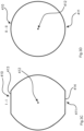
- the outer and inner inner walls 410, 411 of the conveyor line 41 have an unequal radius of curvature R1, R2 in the region of the transition 42, in particular at the transition 42, as shown in the Fig.3E can be clearly seen.
- the outer inner wall 410 is arranged on a side of the conveyor line 41 facing away from a center point M1, M2 of the radius of curvature R1, R2, while the inner inner wall 411 is consequently arranged on a side of the conveyor line 41 facing the center point M1, M2 of the radius of curvature R1, R2.
- the radius of curvature R1 of the outer inner wall 410 is smaller than the radius of curvature R2 of the inner inner wall 411.
- the radii of curvature R1, R2 can also be at least almost the same, with the respective centers M1, M2 of the radii of curvature R1, R2 being offset from one another.
- the center point M1 of the radius of curvature R1 of the outer inner wall 410 is offset towards the conveyor line 41.
- the curvature of the outer inner wall 410 is more pronounced than that of the inner inner wall 411, at least within the transition 42.
- the inner inner wall 411 is essentially linear, in particular at least almost curvature-free, in the area of the transition 42, while the outer inner wall 410 forms a kind of, in particular curved, ramp to the interior 412 of the conveyor line 412.
- the conveyor line 41 forms a kind of overshoot in the conveying direction R in front of the measuring chamber 51, in particular the sensor device 50.
- a cross flow directed with respect to the actual conveying direction R of the granular material G results, which is designed to at least partially to convey and/or redirect in the direction of the interior 412 of the conveying line 41, in particular the cross-section.
- At least one first flattened area 413, 414 is formed on the conveying line 41, in particular on the inner and/or outer inner wall 410, 411, along the at least one oval and/or round cross section I, II.
- the at least partially circular and/or circular arc-shaped geometry of the conveying line 41, in particular of the oval cross section I, has at least one linear, in particular at least almost uncurved, wall when viewed in cross section.
- Such flattened areas and/or cross sections represent a particularly aerodynamic shape for the conveyed air L and/or the granular material G.
- At least one second flattened area 414 is formed on the conveying line 41, in particular on the inner and/or outer inner wall 410, 411, opposite the at least one first flattened area 413.
- the at least one second flattened area 414 is mirror-symmetrical to the at least one first flattened area 413.
- the electronic device 40 in particular the conveyor line 41, is at least partially made of an at least almost wear-resistant, in particular metallic, material in the conveying direction R upstream of the measuring chamber 51.
- at least one metallic insert 44 is arranged for this purpose at an inlet opening 43, in particular at which the granular material G is transferred from the separating element 31 to the electronic device 40 and/or the conveyor line 41.
- the metallic insert 44 is designed to be at least almost wear-resistant and/or shock-resistant compared to the material of the conveyor line 41.
- the electronic device 40, in particular the conveyor line 41 can be at least partially made of and/or coated with wear-resistant material in the region of the curved section, in particular in the region of the transition 42.
- the sensor device 50 shown in the exemplary embodiment is designed in the manner of an optical sensor and is set up to detect the granular material G, in particular in the form of isolated grains, in a contact-free or non-contact manner.
- the sensor device 50 comprises a plurality of sensor elements 52 arranged on the circumference of the conveyor line 41, in particular in the area of the measuring chamber 51 and/or immediately behind the transition 42.
- the sensor elements 52 are designed in the manner of light-emitting diodes and are at least partially assigned to and/or aligned with one another.
- other types of sensors that detect in a contactless manner, in particular via radar and/or light waves, for example radar sensors are also conceivable.
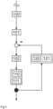
- the granular material G is processed according to the embodiment shown and the schematically illustrated flow diagram in Fig.4 according to the procedure described below.
- the procedure is initiated by the following step: 100) Conveying the granular material G by means of pressure difference and/or gravity through the electronic device 40 with the at least one sensor device 50.
- the following step is carried out: 101) Detecting the granular material G by means of the at least one sensor device 50.
- the sensor device 50 is further designed to generate a sensor signal depending on the detected material G and on the basis of a sensitivity that can be set for the sensor device 50.
- the sensor signal is transmitted via an electronic signal line 53 to a control and/or regulating system 200 assigned to the electronic device 40 and/or the agricultural distribution machine 10.
- the following step is carried out: 102) Determining an actual frequency with which the granular material G passes the electronic device 40, in particular the sensor device 50, on the basis of the sensor signal.
- the following steps are carried out according to the invention: 110) Comparing the determined actual frequency with a retrievable and/or predeterminable target frequency with which the granular material G is conveyed by the electronic device 40; and 111) Determining a deviation between the actual frequency and the target frequency.
- the following step is carried out: 120) Automatic adjustment of the sensor signal and/or sensitivity until the specified acceptance range for the deviation is reached.
- this step can be supplemented by changing the sensor signal using a variably adjustable electronic signal amplifier to adapt the sensor signal.
- the way the electronic signal amplifier works corresponds to a type of electronic magnifying glass, in particular a step-by-step adjustable one.
- the signal level of the sensor signal generated as a result of the detected granular material G can thus be corrected and/or adapted accordingly, so that the determined actual frequency is changed in the direction of the target frequency.
- the sensor device 50 in particular the sensor elements 52, can be provided with an adjustable electrical power supply.
- the sensor device 50 in particular at least one sensor element 52, is designed in the manner of a light source.
- the sensor device 50 can also be assigned an alternative and/or additional light source.
- the light source generates a brightness within the conveyor line 41, in particular within the measuring space 51, which serves to detect the granular material G by the sensor device 50.
- the brightness can be adjusted accordingly depending on the power supply, with the determination of the actual frequency being influenced by the brightness.
- the electrical power supply is thus automatically increased or decreased accordingly until the acceptance range for the deviation is reached.
- the steps described are carried out in particular within a regular calibration process of the electronic device 40, preferably at least partially automated by the control and/or regulation system 200.
- the calibration process can be carried out, for example, annually, daily or during an interruption of the application process. Alternatively or additionally, it is also conceivable that the calibration process of the electronic device 40 also takes place at least almost at the same time and/or simultaneously with the application.
Landscapes
- Life Sciences & Earth Sciences (AREA)
- Soil Sciences (AREA)
- Environmental Sciences (AREA)
- Fertilizing (AREA)
- Measuring Volume Flow (AREA)
- Catching Or Destruction (AREA)
- Sowing (AREA)
Applications Claiming Priority (2)
| Application Number | Priority Date | Filing Date | Title |
|---|---|---|---|
| DE102021104531.2A DE102021104531A1 (de) | 2021-02-25 | 2021-02-25 | Elektronische Vorrichtung zum Erfassen von granularem Material innerhalb einer landwirtschaftlichen Verteilmaschine |
| EP22401003.3A EP4049523B1 (fr) | 2021-02-25 | 2022-02-14 | Procédé de détection sans contact de matériau granulaire dans une machine de distribution agricole |
Related Parent Applications (2)
| Application Number | Title | Priority Date | Filing Date |
|---|---|---|---|
| EP22401003.3A Division EP4049523B1 (fr) | 2021-02-25 | 2022-02-14 | Procédé de détection sans contact de matériau granulaire dans une machine de distribution agricole |
| EP22401003.3A Division-Into EP4049523B1 (fr) | 2021-02-25 | 2022-02-14 | Procédé de détection sans contact de matériau granulaire dans une machine de distribution agricole |
Publications (3)
| Publication Number | Publication Date |
|---|---|
| EP4497312A2 true EP4497312A2 (fr) | 2025-01-29 |
| EP4497312A3 EP4497312A3 (fr) | 2025-04-02 |
| EP4497312B1 EP4497312B1 (fr) | 2026-01-14 |
Family
ID=80685306
Family Applications (2)
| Application Number | Title | Priority Date | Filing Date |
|---|---|---|---|
| EP24219071.8A Active EP4497312B1 (fr) | 2021-02-25 | 2022-02-14 | Dispositif et procédé de détection sans contact de matériau granulaire dans une machine de distribution agricole |
| EP22401003.3A Active EP4049523B1 (fr) | 2021-02-25 | 2022-02-14 | Procédé de détection sans contact de matériau granulaire dans une machine de distribution agricole |
Family Applications After (1)
| Application Number | Title | Priority Date | Filing Date |
|---|---|---|---|
| EP22401003.3A Active EP4049523B1 (fr) | 2021-02-25 | 2022-02-14 | Procédé de détection sans contact de matériau granulaire dans une machine de distribution agricole |
Country Status (5)
| Country | Link |
|---|---|
| EP (2) | EP4497312B1 (fr) |
| DE (1) | DE102021104531A1 (fr) |
| DK (2) | DK4049523T3 (fr) |
| HU (1) | HUE070421T2 (fr) |
| PL (1) | PL4049523T3 (fr) |
Families Citing this family (2)
| Publication number | Priority date | Publication date | Assignee | Title |
|---|---|---|---|---|
| DE102022122898A1 (de) | 2022-09-09 | 2024-03-14 | Amazonen-Werke H. Dreyer SE & Co. KG | Elektronische Vorrichtung zum Erfassen von granularem Material innerhalb einer landwirtschaftlichen Verteilmaschine |
| CN121564041B (zh) * | 2026-01-21 | 2026-03-20 | 中国科学院长春光学精密机械与物理研究所 | 基于局部椭圆弧匹配的冲击波超压场重建方法 |
Citations (3)
| Publication number | Priority date | Publication date | Assignee | Title |
|---|---|---|---|---|
| US5533458A (en) | 1995-03-14 | 1996-07-09 | Deere & Company | Seed tube for an agricultural seeding machine |
| US6332413B1 (en) | 1995-12-29 | 2001-12-25 | Case Corporation | Seed tube for seed metering apparatus |
| DE202004003702U1 (de) | 2004-03-09 | 2004-07-29 | Dressler, Peter | Fitneßgerät zur Körperertüchtigung mit Vibrator |
Family Cites Families (9)
| Publication number | Priority date | Publication date | Assignee | Title |
|---|---|---|---|---|
| US4307390A (en) * | 1979-11-07 | 1981-12-22 | Dickey-John Corporation | Corn and soybean sensor |
| US5650609A (en) * | 1995-05-15 | 1997-07-22 | Phoenix International Corporation | Seed monitoring system for counting seeds as they are dispensed through a seed planting tube |
| CA2291321C (fr) * | 1999-11-30 | 2007-02-13 | Flexi-Coil Ltd. | Appareil et methode de distribution de particules |
| DE102004003702A1 (de) | 2004-01-24 | 2005-08-11 | Amazonen-Werke H. Dreyer Gmbh & Co. Kg | Elektronische Vorrichtung zum Zählen kleiner Körperchen |
| DE102004045655A1 (de) * | 2004-09-21 | 2006-03-23 | Amazonen-Werke H. Dreyer Gmbh & Co. Kg | Elektronische Überwachungseinrichtung |
| US9043950B2 (en) * | 2013-01-02 | 2015-06-02 | Cnh Industrial America Llc | Seed delivery system |
| DE102014115020A1 (de) | 2013-10-21 | 2015-04-23 | Müller-Elektronik Gmbh & Co. Kg | Verfahren und Vorrichtung zur Regelung bzw. zum Erfassen von Masseteilchen |
| EP3135090A1 (fr) | 2015-08-24 | 2017-03-01 | Digitroll Kft. | Capteur et procédé de détection de blocage d'un canal d'ensemencement |
| DE102016204453A1 (de) | 2016-03-17 | 2017-09-21 | Horsch Maschinen Gmbh | Reiheneinheit einer landwirtschaftlichen Maschine |
-
2021
- 2021-02-25 DE DE102021104531.2A patent/DE102021104531A1/de active Pending
-
2022
- 2022-02-14 HU HUE22401003A patent/HUE070421T2/hu unknown
- 2022-02-14 EP EP24219071.8A patent/EP4497312B1/fr active Active
- 2022-02-14 EP EP22401003.3A patent/EP4049523B1/fr active Active
- 2022-02-14 PL PL22401003.3T patent/PL4049523T3/pl unknown
- 2022-02-14 DK DK22401003.3T patent/DK4049523T3/da active
- 2022-02-14 DK DK24219071.8T patent/DK4497312T3/da active
Patent Citations (3)
| Publication number | Priority date | Publication date | Assignee | Title |
|---|---|---|---|---|
| US5533458A (en) | 1995-03-14 | 1996-07-09 | Deere & Company | Seed tube for an agricultural seeding machine |
| US6332413B1 (en) | 1995-12-29 | 2001-12-25 | Case Corporation | Seed tube for seed metering apparatus |
| DE202004003702U1 (de) | 2004-03-09 | 2004-07-29 | Dressler, Peter | Fitneßgerät zur Körperertüchtigung mit Vibrator |
Also Published As
| Publication number | Publication date |
|---|---|
| HUE070421T2 (hu) | 2025-06-28 |
| DK4497312T3 (en) | 2026-02-23 |
| EP4497312A3 (fr) | 2025-04-02 |
| EP4497312B1 (fr) | 2026-01-14 |
| EP4049523A3 (fr) | 2022-11-23 |
| DK4049523T3 (da) | 2025-03-10 |
| DE102021104531A1 (de) | 2022-08-25 |
| EP4049523A2 (fr) | 2022-08-31 |
| EP4049523B1 (fr) | 2025-01-29 |
| PL4049523T3 (pl) | 2025-03-17 |
Similar Documents
| Publication | Publication Date | Title |
|---|---|---|
| EP3409092B1 (fr) | Dispositif de singulation pour matériau granulaire comprenant un compteur de grains | |
| EP2932818B1 (fr) | Dispositif d'épandage et procédé d'épandage de produit granulaire | |
| EP0297309B1 (fr) | Procédé et dispositif de mesure et de régulation du débit de poudre dans une installation de revêtement par poudrage par pulvérisation | |
| EP2246673B1 (fr) | Procédé de détermination du volume de produits à transporter et dispositif | |
| EP4049523B1 (fr) | Procédé de détection sans contact de matériau granulaire dans une machine de distribution agricole | |
| EP3440911A1 (fr) | Semoir à flux de grains suivi | |
| EP2807914B2 (fr) | Dispositif de commande de coeur de semeuse, coeur de semeuse et semeuse de grain individuel | |
| EP1472400B1 (fr) | Procede et dispositif d'humidification d'un faisceau de filaments continu | |
| EP3135089A1 (fr) | Semoir et procédé de commande d'un semoir | |
| DE102015000632A1 (de) | Regelung des Strahlmitteldurchsatzes einer Strahlanlage | |
| WO2016071269A1 (fr) | Semoir pneumatique | |
| EP3241421B1 (fr) | Système de commande de machine agricole et procédé | |
| DE102016208230A1 (de) | Produktverteilungsvorrichtung | |
| EP3301408B1 (fr) | Système de dispositif de mesure d'un débit massique de produit en vrac | |
| DE102022121240A1 (de) | Materialverteilsystem für eine Ausbringmaschine, Ausbringmaschine und Verfahren zum Verteilen von Ausbringmaterial | |
| DE10332869B4 (de) | Verfahren zum Betrieb einer Saugförderanlage und Saugförderanlage | |
| DE102015114146A1 (de) | Dosiervorrichtung für granulares Material mit pneumatischer Nachfüllung | |
| EP3888435A1 (fr) | Machine d'épandage pneumatique agricole | |
| DE102019122441B4 (de) | Einspritzeinheit für eine Formgebungsmaschine, Formgebungsmaschine und Verfahren zum Überprüfen einer Einspritzeinheit einer Formgebungsmaschine | |
| EP3590872A1 (fr) | Dispositif de séparation et d'orientation d'une marchandise de détail sous la forme de tige | |
| DE102010009753A1 (de) | Vorrichtung und Verfahren zur Dosierregelung von Schüttgut | |
| DE102015210212A1 (de) | Verfahren und Vorrichtung zum Ausbringen von körnigem Gut | |
| DE102019122499A1 (de) | Plastifiziereinheit für eine Formgebungsmaschine | |
| DE102005031770B4 (de) | Vorrichtung und Verfahren zum Verteilen von mittels eines Luftstroms geförderten viskosem Schmierstoff | |
| EP0438976A2 (fr) | Dispositif et procédé de contrôle du débit de poudre dans une installation de poudrage |
Legal Events
| Date | Code | Title | Description |
|---|---|---|---|
| PUAI | Public reference made under article 153(3) epc to a published international application that has entered the european phase |
Free format text: ORIGINAL CODE: 0009012 |
|
| STAA | Information on the status of an ep patent application or granted ep patent |
Free format text: STATUS: REQUEST FOR EXAMINATION WAS MADE |
|
| 17P | Request for examination filed |
Effective date: 20241211 |
|
| AC | Divisional application: reference to earlier application |
Ref document number: 4049523 Country of ref document: EP Kind code of ref document: P |
|
| AK | Designated contracting states |
Kind code of ref document: A2 Designated state(s): AL AT BE BG CH CY CZ DE DK EE ES FI FR GB GR HR HU IE IS IT LI LT LU LV MC MK MT NL NO PL PT RO RS SE SI SK SM TR |
|
| REG | Reference to a national code |
Ref country code: DE Ref legal event code: R079 Free format text: PREVIOUS MAIN CLASS: A01C0007200000 Ipc: A01C0007100000 Ref document number: 502022006753 Country of ref document: DE |
|
| PUAL | Search report despatched |
Free format text: ORIGINAL CODE: 0009013 |
|
| AK | Designated contracting states |
Kind code of ref document: A3 Designated state(s): AL AT BE BG CH CY CZ DE DK EE ES FI FR GB GR HR HU IE IS IT LI LT LU LV MC MK MT NL NO PL PT RO RS SE SI SK SM TR |
|
| RIC1 | Information provided on ipc code assigned before grant |
Ipc: A01C 7/20 20060101ALI20250227BHEP Ipc: A01C 7/10 20060101AFI20250227BHEP |
|
| GRAP | Despatch of communication of intention to grant a patent |
Free format text: ORIGINAL CODE: EPIDOSNIGR1 |
|
| STAA | Information on the status of an ep patent application or granted ep patent |
Free format text: STATUS: GRANT OF PATENT IS INTENDED |
|
| RIC1 | Information provided on ipc code assigned before grant |
Ipc: A01C 7/10 20060101AFI20250808BHEP Ipc: A01C 7/20 20060101ALI20250808BHEP |
|
| INTG | Intention to grant announced |
Effective date: 20250902 |
|
| GRAS | Grant fee paid |
Free format text: ORIGINAL CODE: EPIDOSNIGR3 |
|
| GRAA | (expected) grant |
Free format text: ORIGINAL CODE: 0009210 |
|
| STAA | Information on the status of an ep patent application or granted ep patent |
Free format text: STATUS: THE PATENT HAS BEEN GRANTED |
|
| AC | Divisional application: reference to earlier application |
Ref document number: 4049523 Country of ref document: EP Kind code of ref document: P |
|
| AK | Designated contracting states |
Kind code of ref document: B1 Designated state(s): AL AT BE BG CH CY CZ DE DK EE ES FI FR GB GR HR HU IE IS IT LI LT LU LV MC MK MT NL NO PL PT RO RS SE SI SK SM TR |
|
| REG | Reference to a national code |
Ref country code: CH Ref legal event code: F10 Free format text: ST27 STATUS EVENT CODE: U-0-0-F10-F00 (AS PROVIDED BY THE NATIONAL OFFICE) Effective date: 20260114 Ref country code: GB Ref legal event code: FG4D Free format text: NOT ENGLISH |
|
| REG | Reference to a national code |
Ref country code: DE Ref legal event code: R096 Ref document number: 502022006753 Country of ref document: DE |
|
| REG | Reference to a national code |
Ref country code: IE Ref legal event code: FG4D Free format text: LANGUAGE OF EP DOCUMENT: GERMAN |
|
| REG | Reference to a national code |
Ref country code: DK Ref legal event code: T3 Effective date: 20260220 |
|
| PGFP | Annual fee paid to national office [announced via postgrant information from national office to epo] |
Ref country code: HU Payment date: 20260213 Year of fee payment: 5 |
|
| PGFP | Annual fee paid to national office [announced via postgrant information from national office to epo] |
Ref country code: SE Payment date: 20260128 Year of fee payment: 5 |
|
| PGFP | Annual fee paid to national office [announced via postgrant information from national office to epo] |
Ref country code: DK Payment date: 20260310 Year of fee payment: 5 Ref country code: DE Payment date: 20260121 Year of fee payment: 5 |
|
| PGFP | Annual fee paid to national office [announced via postgrant information from national office to epo] |
Ref country code: AT Payment date: 20260301 Year of fee payment: 5 |
|
| PGFP | Annual fee paid to national office [announced via postgrant information from national office to epo] |
Ref country code: FR Payment date: 20260121 Year of fee payment: 5 |