EP4497319A1 - Dispositif de commande pour commander une moissonneuse-batteuse automotrice - Google Patents
Dispositif de commande pour commander une moissonneuse-batteuse automotrice Download PDFInfo
- Publication number
- EP4497319A1 EP4497319A1 EP24176995.9A EP24176995A EP4497319A1 EP 4497319 A1 EP4497319 A1 EP 4497319A1 EP 24176995 A EP24176995 A EP 24176995A EP 4497319 A1 EP4497319 A1 EP 4497319A1
- Authority
- EP
- European Patent Office
- Prior art keywords
- control device
- combine harvester
- speed
- belt
- drive motor
- Prior art date
- Legal status (The legal status is an assumption and is not a legal conclusion. Google has not performed a legal analysis and makes no representation as to the accuracy of the status listed.)
- Pending
Links
Images

Classifications
-
- A—HUMAN NECESSITIES
- A01—AGRICULTURE; FORESTRY; ANIMAL HUSBANDRY; HUNTING; TRAPPING; FISHING
- A01D—HARVESTING; MOWING
- A01D41/00—Combines, i.e. harvesters or mowers combined with threshing devices
- A01D41/12—Details of combines
- A01D41/127—Control or measuring arrangements specially adapted for combines
- A01D41/1274—Control or measuring arrangements specially adapted for combines for drives
-
- A—HUMAN NECESSITIES
- A01—AGRICULTURE; FORESTRY; ANIMAL HUSBANDRY; HUNTING; TRAPPING; FISHING
- A01D—HARVESTING; MOWING
- A01D41/00—Combines, i.e. harvesters or mowers combined with threshing devices
- A01D41/12—Details of combines
- A01D41/127—Control or measuring arrangements specially adapted for combines
- A01D41/1271—Control or measuring arrangements specially adapted for combines for measuring crop flow
- A01D41/1272—Control or measuring arrangements specially adapted for combines for measuring crop flow for measuring grain flow
- A01D41/1273—Control or measuring arrangements specially adapted for combines for measuring crop flow for measuring grain flow for measuring grain loss
-
- A—HUMAN NECESSITIES
- A01—AGRICULTURE; FORESTRY; ANIMAL HUSBANDRY; HUNTING; TRAPPING; FISHING
- A01D—HARVESTING; MOWING
- A01D41/00—Combines, i.e. harvesters or mowers combined with threshing devices
- A01D41/02—Self-propelled combines
-
- A—HUMAN NECESSITIES
- A01—AGRICULTURE; FORESTRY; ANIMAL HUSBANDRY; HUNTING; TRAPPING; FISHING
- A01D—HARVESTING; MOWING
- A01D41/00—Combines, i.e. harvesters or mowers combined with threshing devices
- A01D41/12—Details of combines
- A01D41/127—Control or measuring arrangements specially adapted for combines
- A01D41/1271—Control or measuring arrangements specially adapted for combines for measuring crop flow
-
- A—HUMAN NECESSITIES
- A01—AGRICULTURE; FORESTRY; ANIMAL HUSBANDRY; HUNTING; TRAPPING; FISHING
- A01D—HARVESTING; MOWING
- A01D41/00—Combines, i.e. harvesters or mowers combined with threshing devices
- A01D41/12—Details of combines
- A01D41/14—Mowing tables
- A01D41/141—Automatic header control
-
- A—HUMAN NECESSITIES
- A01—AGRICULTURE; FORESTRY; ANIMAL HUSBANDRY; HUNTING; TRAPPING; FISHING
- A01D—HARVESTING; MOWING
- A01D41/00—Combines, i.e. harvesters or mowers combined with threshing devices
- A01D41/12—Details of combines
- A01D41/14—Mowing tables
- A01D41/142—Header drives
-
- A—HUMAN NECESSITIES
- A01—AGRICULTURE; FORESTRY; ANIMAL HUSBANDRY; HUNTING; TRAPPING; FISHING
- A01D—HARVESTING; MOWING
- A01D43/00—Mowers combined with apparatus performing additional operations while mowing
- A01D43/08—Mowers combined with apparatus performing additional operations while mowing with means for cutting up the mown crop, e.g. forage harvesters
- A01D43/085—Control or measuring arrangements specially adapted therefor
-
- A—HUMAN NECESSITIES
- A01—AGRICULTURE; FORESTRY; ANIMAL HUSBANDRY; HUNTING; TRAPPING; FISHING
- A01D—HARVESTING; MOWING
- A01D57/00—Delivering mechanisms for harvesters or mowers
- A01D57/20—Delivering mechanisms for harvesters or mowers with conveyor belts
Definitions
- the present invention relates to a control device for controlling a self-propelled combine harvester according to the preamble of claim 1. Furthermore, a self-propelled combine harvester and a method for controlling a self-propelled combine harvester are the subject of the present invention.
- a method for detecting a crop jam forming on a working element of a self-propelled combine harvester having multiple working units is determined by evaluating a parameter which is used to monitor the operating state of one of the working units of the combine harvester and comparing it with a threshold value for this parameter which is characteristic of a crop jam forming on this working element.
- the detection of an impending crop jam leads to the control of the working units upstream of the relevant working unit in order to reduce the supply of the crop quantity.
- the speed of the working unit at which the crop jam forms is monitored as such a parameter.
- At least one setting influencing the harvesting operation of the harvesting machine is changed, which leads to a reduction in the amount of crop to be processed, while the settings of the working unit affected by the crop jam remain unchanged.
- This is intended to give the working unit affected by a crop jam time to process the crop already in the working unit, thus avoiding a jam.
- the driving speed is reduced, which reduces the amount of crop taken up.
- the DE 10 2016 115 589 A1 describes a combine harvester with a belt cutting unit, whereby the belt speeds of the conveyor belts of the belt cutting unit are controlled by a control device depending on the driving speed of the combine harvester.
- the belt speeds can be adjusted by a manual Reduce the target to respond to locally occurring lower crop densities in order to even out the crop flow.
- a common feature of the state of the art is that in the case of automatic control of the driving speed of the combine harvester, this is controlled depending on the throughput of the conveyor device in the intake channel.
- the determination of the crop throughput is carried out at a different time in relation to the time at which the crop is taken up by the belt cutting device.
- the invention is based on the object of providing a control device and a method for controlling a self-propelled combine harvester, which is characterized by improved control behavior with a rapidly increasing crop throughput.
- Such an operating situation can occur, for example, when the combine harvester drives through a depression in a field in which, due to a higher water availability, there is a temporarily higher crop yield and thus crop throughput than is the case before the depression.
- a second limit value for the maximum load of the drive motor can be stored or can be stored in the control device, which is greater than the first limit value.
- the second limit value can be used to take into account an operating situation in which the reduction in the belt speed of the conveyor belts of the belt cutting unit alone is no longer sufficient to compensate for the temporary additional load caused by the harvested crop.
- the control device can be designed to reduce the driving speed by controlling the travel drive when the second limit value is reached and to interrupt a respective drive train of the belt cutting device and the conveyor device.
- control device can be set up to reduce the driving speed depending on the throughput when the first limit value is reached.
- the reduced crop feed achieved by the control of the belt speed of the conveyor belts according to the invention can be supplemented by the belt cutting device by relieving the belt cutting device as such for the duration of the control.
- control device can be designed to reduce the drive speed of the cutter bar and intake auger of the belt cutting unit.
- This measure can contribute to reducing the load on the drive motor.
- This measure can also contribute to reducing the amount of crop fed to the working units downstream of the intake channel.
- control device is designed to change the belt speed of the conveyor belts and the drive speed of the knife bar and intake auger of the belt cutting device independently of one another by controlling actuators for driving the conveyor belts, the knife bar and the intake auger. This makes it possible to react more flexibly to fluctuations in the amount of crop taken up by the belt cutting device, both in the event of an increase or a decrease in the amount of crop.
- control device can be designed to control or regulate the driving speed of the combine harvester depending on the throughput. This enables the combine harvester to be operated essentially at the limit of the drive motor's capacity in order to achieve the highest possible campaign performance.
- control device can be designed to receive and evaluate signals for determining the crop throughput from a sensor arrangement arranged in the intake channel.
- control device can be designed to receive and evaluate signals for determining crop losses from at least one loss sensor arrangement assigned to the combine harvester and to control or regulate the driving speed of the combine harvester depending on the detected crop losses.
- control device can be set up to operate the combine harvester in different, adjustable driving modes, wherein a driving mode specifies a constant driving speed for which a target driving speed to be maintained is specified, a driving mode specifies a constant crop throughput for which a target crop throughput is specified in order to to adjust the driving speed, or a driving mode specifies a constant crop throughput at a predetermined loss level, for which a target crop throughput and a target loss level to be maintained are specified in order to adjust the driving speed.
- a driving mode specifies a constant driving speed for which a target driving speed to be maintained is specified
- a driving mode specifies a constant crop throughput for which a target crop throughput is specified in order to to adjust the driving speed
- a driving mode specifies a constant crop throughput at a predetermined loss level, for which a target crop throughput and a target loss level to be maintained are specified in order to adjust the driving speed.
- the belt cutting unit can have a knife bar, several driven conveyor belts and an intake screw, whereby the knife bar and the intake screw are mechanically driven and the conveyor belts are hydraulically driven.
- the provision of different drive types through a mechanical drive train and a hydraulic drive train enables the knife bar and intake screw on the one hand and the driven conveyor belts on the other hand to be controlled independently of one another in order to be able to react more individually to fluctuations in the crop density and/or the driving speed.
- the driven conveyor belts of the belt cutting unit can be operated with independently adjustable belt speeds.
- a method for controlling a self-propelled combine harvester which comprises a belt cutting unit having a plurality of conveyor belts driven at a belt speed for receiving and conveying harvested material to a conveyor device in the intake channel of the combine harvester, a plurality of working units arranged downstream of the intake channel for processing the received harvested material, and a drive motor by which the belt cutting unit, the working units and a travel drive are driven.
- the utilization of the drive motor during harvesting is determined by the control device and that when a first limit value for a limit utilization of the drive motor, which is stored or can be stored in the control device, is passed, the belt speed of the conveyor belts of the band cutting device is reduced.
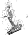
- Fig. 1 is a schematic and exemplary partial view of a self-propelled combine harvester 1.
- the combine harvester 1 accommodates an attachment designed as a belt cutting device 2 in its front area, which is connected in a manner known per se to a conveyor device 5 arranged in the intake channel of the combine harvester 1.
- the belt cutting device 2 has a reel 3 arranged on support arms and a feed roller 4 arranged upstream of the conveyor device 5.
- Conveyor elements 6 of the conveyor device 5, designed as an inclined conveyor, are guided on the top so that they can pivot about a pivot axis 7 transversely to the longitudinal direction of the combine harvester 2.
- a sensor arrangement 8 is arranged in the intake channel, which provides signals for determining the crop throughput.
- a layer height roller known per se is assigned to the conveyor elements 6 in a central area as a sensor arrangement 8.
- the deflection of the sensor arrangement 8, designed as a layer height roller, in the vertical direction is a measure of a layer height 9 of a crop flow 10 passing through the conveyor device 5.
- the crop flow 10 passing through the conveyor device 5 is transferred in the upper, rear area of the conveyor device 5 to the threshing elements 12 of the combine harvester 1, which are at least partially covered by a so-called threshing concave 11 on the bottom.
- a deflection drum 13 arranged downstream of the threshing elements 12 deflects the crop flow 10 emerging from the threshing elements 12 in the rear area so that it is transferred directly to a separating device 15 designed as a separating rotor arrangement 14. It is within the scope of the invention that the separating device 15 can also be designed as a tray shaker, which is known per se and therefore not shown.
- the separating rotor arrangement 14 is designed with only one separating rotor or that the threshing elements 12 and the separating device 15 are combined to form a one- or two-rotor axial flow threshing and separating device.
- the crop stream 10 is conveyed in such a way that freely moving grains 16 contained in the crop stream 10 are separated in the lower area of the separating device 15. Both the grains 16 separated on the threshing concave 11 and in the separating device 15 are fed via the return floor 17 and feed floor 18 to a cleaning device 22 consisting of several sieve levels 19, 20 and a blower 21. The cleaned grain stream 25 is finally transferred to a grain tank 24 by means of an elevator 23.
- a shredding device 28 designed as a straw chopper 27 is assigned to it, which is enclosed in a funnel-shaped housing 26. Straw 30 leaving the separating device 15 in the rear area is fed to the straw chopper 27 from above. By means of a pivoting straw guide flap 29, the straw 30 can also be diverted so that it is deposited directly on the ground 31 in a swath.
- the material flow consisting of the shredded straw 30 and the non-grain components separated in the cleaning device 22 are transferred to a material distribution device 32.
- the material distribution device 32 releases a residual material flow 33 consisting essentially of the straw 30 and the non-grain components in such a way that the residual material flow 33 is widely distributed on the floor 31.
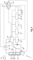
- the representation in Fig. 2 shows a schematic and exemplary view of the belt cutting device 3.
- the belt cutting device 3 has a knife bar 35 which separates the crop 36 to be harvested.
- the knife bar 35 can be either rigid or flexible. It is also conceivable that the flexible knife bar 35 can be operated rigidly.
- a flexible knife bar 35 can better follow changes in the ground contour in the longitudinal and transverse directions in a known manner.
- at least one left-hand conveyor belt 38, at least one right-hand conveyor belt 39 and a central conveyor belt 40 are arranged downstream of the knife bar 35 in the feed direction 37 of the harvested crop 36.
- the left-hand conveyor belt 38 conveys the harvested crop stock 36 it has picked up in the direction of the arrow 41 towards the central conveyor belt 40 and transfers it to the latter.
- the right-hand conveyor belt 39 conveys the harvested crop stock 36 it has picked up in the direction of the arrow 42 also towards the central conveyor belt 40 and transfers it to the latter.
- the central conveyor belt 40 then conveys the crop stock 36 it has picked up and transferred from the conveyor belts 38, 39 to the conveyor belt 40 into the rear area of the belt cutting unit 2 in the direction of the arrow 43. In this rear area, the crop stock 36 is picked up by the rotating intake roller 4 assigned to this area and transferred as the aforementioned crop stream 10 to the conveyor device 5 in the intake channel of the combine harvester 1.
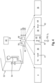
- a drive motor 44 and a control device 45 for the combine harvester 1 is shown schematically and by way of example.
- the self-propelled combine harvester 1 is controlled by means of the control device 45.
- the control device 45 comprises a storage unit 47 and a computing unit 48.
- the drive motor 44 is generally designed as an internal combustion engine. In addition to the belt cutting unit 2, the conveyor device 5 in the intake channel, and the working units arranged downstream of the conveyor device 5, the drive motor 44 drives a particularly hydrostatic drive 46 of the combine harvester 1 in order to move it over the ground 31 at a controllable or adjustable travel speed VF during the harvesting process.
- the conveyor belts 38, 39, 40 of the belt cutting unit 2 are driven here and preferably hydraulically.
- the conveyor belts 38, 39, 40 are connected to a hydraulic drive train 49.
- the conveyor belts 38, 39, 40 each have a controllable or adjustable actuator 51, which is preferably designed as a hydraulic motor.
- the individual actuators 51 of the conveyor belts 38, 39, 40 are controlled by the control device 45.
- the conveyor belts 38, 39, 40 are driven with a belt speed VL for the left-hand conveyor belt 38, with a belt speed VM for the central conveyor belt 40 and with a belt speed VR for the right-hand conveyor belt 39.
- the belt speeds VL, VM and VR can be adjusted independently of one another by individually controlling the actuators 51.
- the knife bar 35, the reel 3 and the feed screw 4 are preferably driven mechanically independently of the conveyor belts 38, 39, 40.
- the knife bar 35, the reel 3 and the feed screw 4 are connected to the drive motor 44 by a mechanical drive train 50.
- the mechanical drive train 50 can comprise a gear as a controllable or adjustable actuator 52.
- the actuator 52 is controlled by the control device 45.
- the control device 45 is connected by signal lines to the drive motor 44, the travel drive 46 and the controllable actuators 51 of the hydraulic drive train 49 and the actuator 52 of the mechanical drive train 50 for receiving operating parameters and for transmitting control commands.
- the control device 45 is also connected by a signal line to the sensor arrangement 8 arranged in the intake channel for determining the crop throughput.
- the control device 45 is set up to continuously evaluate a signal generated by the sensor arrangement 8 relating to the layer height 9 in the intake channel.
- the control device 45 is designed to operate the self-propelled combine harvester 1 in different driving modes.
- the different driving modes are adjustable.
- a driving mode a constant driving speed VF is specified, at which a target driving speed is specified.
- An alternative driving mode specifies a constant crop throughput, at which a target crop throughput is specified. in order to adjust the driving speed VF depending on the target crop throughput.
- Another driving mode specifies a constant crop throughput at a specified loss level, in which a target crop throughput and a target loss level to be maintained are specified in order to adjust the driving speed VF depending on the target crop throughput and the target loss level to be maintained.
- the control device 45 is set up to receive and evaluate signals for determining crop losses from at least one loss sensor arrangement 57 assigned to the combine harvester 1 in order to control or regulate the driving speed VF of the combine harvester 1 depending on the crop losses detected by the at least one loss sensor arrangement 57 and the crop throughput detected by the sensor arrangement 8.
- the at least one loss sensor arrangement 57 is arranged downstream of the cleaning device 22.
- the different driving modes are stored or can be stored in the memory unit 47 of the control device 45.
- the different parameters of the driving modes can be specified and changed using a user interface (not shown).
- the control device 45 is designed and configured to determine the utilization of the drive motor 44 during the harvesting operation and to reduce the belt speed of the conveyor belts 38, 39, 40 of the belt cutting unit 2 when a first limit value 55 stored or capable of being stored in the control device 45 for a limit utilization of the drive motor 44 is passed.
- Fig. 4 is shown schematically and by way of example a representation of a control of the combine harvester 1 by the control device 45.
- a cabin 53 of the combine harvester 1 there is at least one control element 54 with which the driving speed VF or one of the driving modes stored in the memory unit 47 can be selected and/or adjusted in order to control the driving drive 46 according to the selected driving mode.
- FR designates the direction of travel when the combine harvester 1 enters the crop 36 in order to harvest it.
- the belt speed VL, VR, VM of the conveyor belts 38, 39, 40 is reduced so that the volume flow with already collected crop, which is fed to the combine harvester 1 from the belt cutting unit 2, is reduced.
- a second limit value 56 for the maximum load of the drive motor 44 is stored or can be stored in the control device 45, which is greater than the first limit value 55.
- the second limit value 56 can be used to take into account an operating situation in which the reduction of the belt speeds VL, VR, VM of the conveyor belts 38, 39, 40 alone is no longer sufficient to compensate for the temporary additional load caused by the harvested crop during conveyance and processing by the working units of the combine harvester 1.
- control device 45 can be designed to reduce the travel speed VF by controlling the travel drive 46 and to interrupt the hydraulic drive train 49 of the belt cutting unit 2 and the drive train of the conveyor device 5 when the second limit value 56 for the utilization of the drive motor 44 is reached.
- control device 45 is designed to reduce the driving speed VF depending on the throughput when the first limit value 55 is reached. This can prevent the collected crop from accumulating in the belt cutting device 2.
- control device 45 is designed to reduce the drive speed of the knife bar 35 and the intake auger 4 of the belt cutting device 2.
- the control device 45 can control the actuators 52 in the mechanical drive train 50 of the belt cutting device 2.
Landscapes
- Life Sciences & Earth Sciences (AREA)
- Environmental Sciences (AREA)
- Harvester Elements (AREA)
- Outside Dividers And Delivering Mechanisms For Harvesters (AREA)
Applications Claiming Priority (1)
| Application Number | Priority Date | Filing Date | Title |
|---|---|---|---|
| DE102023119957.9A DE102023119957A1 (de) | 2023-07-27 | 2023-07-27 | Steuerungsvorrichtung zur Ansteuerung eines selbstfahrenden Mähdreschers |
Publications (1)
| Publication Number | Publication Date |
|---|---|
| EP4497319A1 true EP4497319A1 (fr) | 2025-01-29 |
Family
ID=91193289
Family Applications (1)
| Application Number | Title | Priority Date | Filing Date |
|---|---|---|---|
| EP24176995.9A Pending EP4497319A1 (fr) | 2023-07-27 | 2024-05-21 | Dispositif de commande pour commander une moissonneuse-batteuse automotrice |
Country Status (3)
| Country | Link |
|---|---|
| US (1) | US20250031616A1 (fr) |
| EP (1) | EP4497319A1 (fr) |
| DE (1) | DE102023119957A1 (fr) |
Families Citing this family (1)
| Publication number | Priority date | Publication date | Assignee | Title |
|---|---|---|---|---|
| CN120240137B (zh) * | 2025-05-30 | 2025-11-28 | 山东常美机械制造有限公司 | 一种基于强化学习的玉米收割机节能调控方法、系统 |
Citations (6)
| Publication number | Priority date | Publication date | Assignee | Title |
|---|---|---|---|---|
| EP2377385A1 (fr) * | 2010-04-16 | 2011-10-19 | CLAAS Selbstfahrende Erntemaschinen GmbH | Procédé d'établissement d'un amoncèlement de récolte se développant sur un organe de travail d'une moissonneuse automobile et dispositif de commande |
| EP3114919A1 (fr) * | 2015-07-08 | 2017-01-11 | Zürn Harvesting GmbH & Co. KG | Systeme de tête de coupe |
| DE102016115589A1 (de) | 2016-08-23 | 2018-03-01 | Claas Selbstfahrende Erntemaschinen Gmbh | Bandschneidwerk |
| DE102016223133A1 (de) * | 2016-11-23 | 2018-05-24 | Deere & Company | Geschwindigkeitskontrolle einer Erntemaschine |
| DE102018212075A1 (de) * | 2018-07-19 | 2020-01-23 | Deere & Company | Mähdrescher mit einem Schrägförderer mit aktorisch verstellbarer, unterer Umlenkwalze |
| US20200367434A1 (en) * | 2017-11-28 | 2020-11-26 | Kubota Corporation | Harvester |
-
2023
- 2023-07-27 DE DE102023119957.9A patent/DE102023119957A1/de active Pending
-
2024
- 2024-05-21 EP EP24176995.9A patent/EP4497319A1/fr active Pending
- 2024-07-29 US US18/786,900 patent/US20250031616A1/en active Pending
Patent Citations (7)
| Publication number | Priority date | Publication date | Assignee | Title |
|---|---|---|---|---|
| EP2377385A1 (fr) * | 2010-04-16 | 2011-10-19 | CLAAS Selbstfahrende Erntemaschinen GmbH | Procédé d'établissement d'un amoncèlement de récolte se développant sur un organe de travail d'une moissonneuse automobile et dispositif de commande |
| EP2377385B1 (fr) | 2010-04-16 | 2013-04-17 | CLAAS Selbstfahrende Erntemaschinen GmbH | Procédé d'établissement d'un amoncellement de récolte se développant sur un organe de travail d'une moissonneuse automobile et dispositif de commande |
| EP3114919A1 (fr) * | 2015-07-08 | 2017-01-11 | Zürn Harvesting GmbH & Co. KG | Systeme de tête de coupe |
| DE102016115589A1 (de) | 2016-08-23 | 2018-03-01 | Claas Selbstfahrende Erntemaschinen Gmbh | Bandschneidwerk |
| DE102016223133A1 (de) * | 2016-11-23 | 2018-05-24 | Deere & Company | Geschwindigkeitskontrolle einer Erntemaschine |
| US20200367434A1 (en) * | 2017-11-28 | 2020-11-26 | Kubota Corporation | Harvester |
| DE102018212075A1 (de) * | 2018-07-19 | 2020-01-23 | Deere & Company | Mähdrescher mit einem Schrägförderer mit aktorisch verstellbarer, unterer Umlenkwalze |
Also Published As
| Publication number | Publication date |
|---|---|
| US20250031616A1 (en) | 2025-01-30 |
| DE102023119957A1 (de) | 2025-01-30 |
Similar Documents
| Publication | Publication Date | Title |
|---|---|---|
| EP3662741B2 (fr) | Machine de travail agricole ainsi que procédé de fonctionnement d'une machine de travail agricole | |
| EP1543712B1 (fr) | Procédé et dispositif pour régler les organes de travail d'une moissonneuse-batteuse | |
| EP3533315B1 (fr) | Récolteuse-hacheuse-chargeuse de fourrage et procédé de fonctionnement d'une récolteuse-hacheuse-chargeuse de fourrage | |
| EP1493318B1 (fr) | Procédé de control d'un ensemble de battage pour moissonneuse-batteuse | |
| EP3542610B1 (fr) | Ramasseuse-hacheuse | |
| EP3286999B1 (fr) | Coupe-rubans | |
| EP2550851B1 (fr) | Dispositif de nettoyage pour une moissonneuse-batteuse | |
| DE102017208442A1 (de) | Selbstlernende, Korrektureingaben berücksichtigende Anordnung zur selbsttätigen Kontrolle eines Arbeitsparameters einer Erntegutförder- und/oder -bearbeitungseinrichtung | |
| EP2550852A1 (fr) | Procédé de commande d'un processus de récolte d'une moissonneuse-batteuse | |
| EP3494771A1 (fr) | Dispositif de hauteur de coupe automatique | |
| EP2702858A2 (fr) | Moissonneuse agricole avec régulation de l'acheminement de produits | |
| EP3395158A1 (fr) | Moissonneuse-batteuse | |
| DE102020204859A1 (de) | Erntesteuerungssystem mit messerbalken-lasterfassung | |
| EP3597027B1 (fr) | Moissonneuse-batteuse doté d'un convoyeur incliné pourvu de rouleau de déviation inférieur réglable | |
| EP4388856B1 (fr) | Moissonneuse dotée d'un appareil de récolte comprenant un capteur de perte de grain | |
| EP4154699B1 (fr) | Machine de travail agricole pourvu à commande de champ caractéristique | |
| DE102023119957A1 (de) | Steuerungsvorrichtung zur Ansteuerung eines selbstfahrenden Mähdreschers | |
| EP2848113B1 (fr) | Dispositif de nettoyage pour une moissonneuse-batteuse | |
| EP4154697B1 (fr) | Système d'aide à la conduite d'un engin d'abattage-façonnage pourvu de mécanisme de coupe de bande | |
| EP0693252A1 (fr) | Moissonneuse-batteuse à régulation de ventilation | |
| EP4154700A1 (fr) | Engin d'abattage-façonnage pourvu de mécanisme de coupe de bande | |
| EP1470749B1 (fr) | Système batteur-séparateur | |
| EP2805602A2 (fr) | Moissonneuse-batteuse | |
| EP4111846A1 (fr) | Procédé et appareil de commande permettant de faire fonctionner un engin d'abattage-façonnage agricole et engin d'abattage-façonnage agricole | |
| DE102021110556A1 (de) | Mähdrescher sowie Verfahren zum Betreiben eines Mähdreschers |
Legal Events
| Date | Code | Title | Description |
|---|---|---|---|
| PUAI | Public reference made under article 153(3) epc to a published international application that has entered the european phase |
Free format text: ORIGINAL CODE: 0009012 |
|
| STAA | Information on the status of an ep patent application or granted ep patent |
Free format text: STATUS: THE APPLICATION HAS BEEN PUBLISHED |
|
| AK | Designated contracting states |
Kind code of ref document: A1 Designated state(s): AL AT BE BG CH CY CZ DE DK EE ES FI FR GB GR HR HU IE IS IT LI LT LU LV MC ME MK MT NL NO PL PT RO RS SE SI SK SM TR |
|
| P01 | Opt-out of the competence of the unified patent court (upc) registered |
Free format text: CASE NUMBER: APP_6777/2025 Effective date: 20250210 |
|
| STAA | Information on the status of an ep patent application or granted ep patent |
Free format text: STATUS: REQUEST FOR EXAMINATION WAS MADE |
|
| 17P | Request for examination filed |
Effective date: 20250729 |