EP4497320A1 - Landwirtschaftliche maschine zur verteilung eines produkts fur die fütterung von tieren und/oder die bildung von einstreu - Google Patents
Landwirtschaftliche maschine zur verteilung eines produkts fur die fütterung von tieren und/oder die bildung von einstreu Download PDFInfo
- Publication number
- EP4497320A1 EP4497320A1 EP24187956.8A EP24187956A EP4497320A1 EP 4497320 A1 EP4497320 A1 EP 4497320A1 EP 24187956 A EP24187956 A EP 24187956A EP 4497320 A1 EP4497320 A1 EP 4497320A1
- Authority
- EP
- European Patent Office
- Prior art keywords
- rotation
- door
- complementary member
- axis
- complementary
- Prior art date
- Legal status (The legal status is an assumption and is not a legal conclusion. Google has not performed a legal analysis and makes no representation as to the accuracy of the status listed.)
- Pending
Links
Images


Classifications
-
- A—HUMAN NECESSITIES
- A01—AGRICULTURE; FORESTRY; ANIMAL HUSBANDRY; HUNTING; TRAPPING; FISHING
- A01D—HARVESTING; MOWING
- A01D90/00—Vehicles for carrying harvested crops with means for selfloading or unloading
- A01D90/02—Loading means
- A01D90/08—Loading means with bale-forming means additionally used for loading; with means for picking-up bales and transporting them into the vehicle
- A01D90/083—Round-bale trailers
-
- A—HUMAN NECESSITIES
- A01—AGRICULTURE; FORESTRY; ANIMAL HUSBANDRY; HUNTING; TRAPPING; FISHING
- A01B—SOIL WORKING IN AGRICULTURE OR FORESTRY; PARTS, DETAILS, OR ACCESSORIES OF AGRICULTURAL MACHINES OR IMPLEMENTS, IN GENERAL
- A01B63/00—Lifting or adjusting devices or arrangements for agricultural machines or implements
- A01B63/02—Lifting or adjusting devices or arrangements for agricultural machines or implements for implements mounted on tractors
- A01B63/10—Lifting or adjusting devices or arrangements for agricultural machines or implements for implements mounted on tractors operated by hydraulic or pneumatic means
- A01B63/118—Mounting implements on power-lift linkages
-
- A—HUMAN NECESSITIES
- A01—AGRICULTURE; FORESTRY; ANIMAL HUSBANDRY; HUNTING; TRAPPING; FISHING
- A01B—SOIL WORKING IN AGRICULTURE OR FORESTRY; PARTS, DETAILS, OR ACCESSORIES OF AGRICULTURAL MACHINES OR IMPLEMENTS, IN GENERAL
- A01B63/00—Lifting or adjusting devices or arrangements for agricultural machines or implements
- A01B63/02—Lifting or adjusting devices or arrangements for agricultural machines or implements for implements mounted on tractors
- A01B63/10—Lifting or adjusting devices or arrangements for agricultural machines or implements for implements mounted on tractors operated by hydraulic or pneumatic means
-
- A—HUMAN NECESSITIES
- A01—AGRICULTURE; FORESTRY; ANIMAL HUSBANDRY; HUNTING; TRAPPING; FISHING
- A01D—HARVESTING; MOWING
- A01D87/00—Loaders for hay or like field crops
- A01D87/12—Loaders for sheaves, stacks or bales
- A01D87/127—Apparatus for handling, loading or unrolling round bales
-
- A—HUMAN NECESSITIES
- A01—AGRICULTURE; FORESTRY; ANIMAL HUSBANDRY; HUNTING; TRAPPING; FISHING
- A01D—HARVESTING; MOWING
- A01D87/00—Loaders for hay or like field crops
- A01D87/12—Loaders for sheaves, stacks or bales
- A01D87/127—Apparatus for handling, loading or unrolling round bales
- A01D2087/128—Devices for unrolling or breaking round bales
Definitions
- the present invention relates to the field of agricultural machinery and more particularly to agricultural machinery for distributing products for feeding animals and/or forming their litter.
- the subject of the present invention is such a machine.
- These agricultural distribution machines are equipped with loading means in the form of a door allowing the loading of products for feeding animals and/or forming their bedding.
- These products generally straw or hay in the form of bales produced by a baler, are loaded into a box of the machine for distribution. They also include wheels to allow them to move on the ground.
- the door is mounted in a tilting manner around an axis located in the lower part of the machine casing.
- the door is actuated by means of at least one hydraulic cylinder articulated in rotation on the casing and on the door.
- the door is located at the rear of the casing and tilts between a closed position and an open position.
- the door is used in particular to close a loading opening made in the casing, generally at the rear of the casing. The open position of the door allows the loading of products into the casing of the distribution machine.
- the document FR2773947 provides a solution to this problem with a device allowing the operator to directly load a bale.
- the device comprises a complementary member capable of being slid under the bale after having correctly positioned the rear part of the box in which the door is located relative to the bale to be loaded.
- the complementary member extends from the door in the extension of the latter when it rests on the ground.
- the complementary member in the form of a hoop, is articulated around an axis of rotation parallel to the axis of rotation of the door on the box.
- the complementary member when the door is closed, the complementary member remains in the same position as that allowing the blocking of the bale (forming a folded position relative to the plane of the door) and extends at least into, or even above, the box, which has the effect of creating an obstacle to loading from above. Furthermore, the position of the complementary member is fixed above the box when the door is closed. This position of the complementary member therefore increases the height requirement and prevents the use of the distribution machine for certain hangars, the access entrance of which is too low.
- the present invention aims to overcome these drawbacks by proposing an agricultural machine for distributing products for feeding animals and/or forming their litter, allowing greater versatility and better adaptation to the environment and to loading and usage conditions.
- the agricultural machine for distributing products for feeding animals and/or forming their litter comprising a box and a product loading door articulated in rotation on the box about a first axis of rotation, a complementary member articulated in rotation on the door about a second axis of rotation and at least one main cylinder for actuating the door articulated in rotation on the box about a third axis of rotation and on the door about a fourth axis of rotation, is characterized in that it further comprises a device for managing the rotation of the complementary member relative to the door comprising:
- the product is in the form of a bale, for example a cylindrical bale.
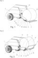
- a bale of product B can be loaded onto the door 2.
- the complementary member 3 extends in the extension of the door and also rests on the ground S.
- the gate 2 extends into an intermediate position, in which it is raised relative to the ground S. In this intermediate position, the cylindrical bale is held in equilibrium in the gate 2. This position makes it possible, for example, to cut the ties surrounding the bale before it enters the box 1 to be distributed.
- the gate 2 passes from its open position to its closed position and vice versa, it necessarily passes through the intermediate position.
- the box 1 may comprise a loading opening 10.
- the loading opening 10 is located at the rear of the box 1 (or of the machine) to allow loading of the product packaged in the form of a bale in reverse, when the door is in the open position.
- the box 1 may comprise two walls delimiting between them at the rear of the box a space forming the loading opening 10.
- the box is advantageously formed by the two side walls of the box 1 and the loading door 2.
- At the front of the box 1 is a disentangling and ejection device.
- the bottom of the box 1 consists of a floor equipped with a movement device.
- This movement device allows the product to be moved from the rear to the front of the box 1.
- the product is moved towards the disentangling and ejection device.
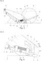
- the door 2 is mounted in rotation, more particularly in a tilting manner, between the closed position of the loading opening 10 ( figures 5 , 6 ) and an open position.
- the open position door 2 is placed on the floor S ( figures 1 , 3 ).
- the door 2 can be controlled so as to be held in an intermediate open position between the closed position and the open position placed on the ground S.
- a bale of product B can be loaded into the door 2 ( figures 1 And 3 ) for its introduction into box 1 under the effect of the closing of door 2.
- the complementary member 3 also makes it possible, in a folded position, to retain the bale after the net or string surrounding it (not shown) to keep it in shape has been cut.
- figure 3 represents in continuous lines this folded position of the complementary member 3.
- the ball of product B may, instead of being cylindrical in shape, be parallelepipedal in shape.
- the complementary member 3 makes it possible to extend the end part of the door 2 to ensure that the ball remains on the door 2 when it swings towards the closed position and is loaded into the box 1.
- the axis of rotation X2 of the complementary member 3 can be located near the free end of the door 2. If necessary, the axis of rotation X2 can be located near the end part of the door 2, that is to say opposite the axis of rotation X1 of the door 2 on the box 1.
- the complementary organ 3 of the figure 6 is unfolded while it is folded on the figure 5 .
- the folding of the complementary organ 3 as shown in the figure 5 allows the height of the agricultural distribution machine to be reduced, so as to allow its access to buildings with limited access height.
- the unfolded position of the complementary member 3 ( figure 6 ) advantageously allows loading of the box 1 from the top, the door 2 being in its closed position.
- the position of the complementary member 3 of the present invention is therefore not constrained to the position of the door 2, the versatility of the distribution machine is thus increased.
- the body 40 of the or each main cylinder 4 can be articulated in rotation on the box 1 around the third axis of rotation X3 and the rod 41 of the or each main cylinder 4 can be mounted in rotation, at its end, on the complementary member 3 around the fourth axis of rotation X4.
- the body of the or each main cylinder 4 can be articulated in rotation on the complementary member by means of the fourth axis of rotation X4 and the rod of the or each main cylinder 4 can be fixed to the box by means of the third axis of rotation X3.
- the at least one rotation switch 5 is configured to generate the rotation of the complementary member 3 relative to the door 2 when the torque applied by the or each main cylinder 4 to the complementary member 3 is greater than a retaining force applied by the switch(es) 5 to the complementary member 3 and opposing the rotation of the complementary member 3 and then to generate the rotation of the door 2 equipped with the complementary member 3 when the torque applied by the or each main cylinder 4 to the complementary member 3 is less than the retaining force.
- the or each main cylinder 4 can be articulated (around the fourth axis of rotation X4) on a lever arm 30 formed by a part of the complementary member 3.
- the lever arm 30 can be integrated into the complementary member 3 (made from scratch during manufacture with the latter) or be added in/onto it.
- the lever arm 30 can extend between the second axis of rotation X2 and the fourth axis of rotation X4.
- the cam and indexing path 52 has a circular arc tooth shape.
- the different indexing notches 520 produce the circular arc tooth shape.
- the lock 50 is then made radially movable relative to the cam and indexing path 52.
- a bearing system 53 integral with the complementary member 3 makes it possible to ensure the guidance of the follower lock 50.
- the cam and indexing path 52 comprises at least one stop 521, 522.
- the cam and indexing path 52 comprises two end-of-travel stops 521, 522, respectively an upper stop 521 and a lower stop 522.
- the complementary member 3 has at least one contact face 33 capable and intended to come into abutment against one of the stops 521, 522.
- the upper stop 521 defines a limit of rotation of the complementary member 3 in the folded position ( figures 2 , 3 , 5 ) and the lower stop 522 defines a rotation limit of the complementary member 3 in the unfolded position ( figures 1 , 3 , 4 , 6 ).
- the longitudinal axis of the follower lock 50 is preferably substantially parallel to the plane perpendicularly intersecting the second and fourth axes of rotation X2, X4 parallel to each other.
- the or each rotation switch 5 may consist of a friction mechanism or a cylinder and accumulator type mechanism.
- the operation of the management device can be as follows, considering a management device comprising a main cylinder 4 and a rotation switch 5 on either side of the door 2:
- the complementary member can adapt freely and follow the slope of the ground S to facilitate the loading of the bale of product B.
- the additional position allows the base of the door 2 and the complementary member 3 to rest on the ground S. With such a distribution machine, it is necessary to consider a closing phase of the door 2 with a bale of product B and a closing phase of the door 2 without a bale of product B.
- the resulting force in the main cylinder 4 is also low.
- the contact force resulting from this torque between the follower lock 50 and the cam and indexing path 52 does not allow the spring 51 to be compressed (force less than the return force of the spring 51).
- the follower lock 50 does not move, the end 500 remains in its indexing notch 520.
- the complementary member 3 does not move relative to the door 2, which tilts upwards under the effect of the output of the rod 41 of the main cylinder 4.
- the door 2 and the complementary member 3 will therefore rise until the door 2 comes to a stop against the threshold of the loading opening 10 of the box 1.
- the complementary member 3 maintains its position in the indexing notch 520.
- the force in the or each main cylinder 4 increases, which has the effect that the compression force of the spring 51 increases until it reaches the value of the return force (or preload) of the spring 51 causing the compression of the spring 51 and therefore a withdrawal of the follower lock 50 (more particularly of its end 500) from the first or second indexing notch 520.
- the follower lock 50 passes the first or second indexing notch 520, then successively the other indexing notches 520 generating a movement of the follower lock 50 relative to the cam and indexing path 52.
- the effort to move door 2 is greater than in the empty case, due to the weight of the load (product B).
- the load several hundred kilograms, present on door 2 makes it possible to overcome the return force of spring 51, which generates a rotational movement of the complementary member 3 relative to door 2.
- the management device therefore allows the complementary member 3 to pivot towards its folded position without moving the door 2.
- the main cylinder 4 is actuated to lift the door 2 under load, the complementary member 3 pivots as a priority thanks to the rotation switch 5. If the torque of the main cylinder 4 on the door 2 increases sufficiently, the door 2 lifts off the ground S by rotating around the first axis of rotation X1, otherwise the rotational movement of the complementary member 3 continues up to the contact face 33.
- the force in the main cylinder 4 increases further, which allows the door 2 to be lifted in order to introduce the bale of product B into the box 1.
- the force to move the door 2 is low.
- the force in the resulting main cylinder 4 is also low.
- the torque generated on the complementary member 3 around the second axis of rotation X2 then remains low.
- the contact force resulting from this torque between the follower lock 50 and the cam and indexing path 52 does not allow the spring 51 to be compressed (force less than the return force of the spring 51).
- the follower lock 50 does not move and the complementary member 3 maintains its position relative to the door 2 which is moved in rotation.
- the door 2 will therefore lower under the effect of the retraction of the rod 41 of the main cylinder 4, until it reaches the stop against the ground S.
- the force in the main cylinder 4 increases, this is reflected in the compression force of the spring 51 which increases until reaching the value of the return force (preload) of the spring. Only then does the spring 51 compress, causing the retraction movement of the follower lock 50 and therefore the movement of the follower lock 50 relative to the cam and indexing path 52. This generates a rotation movement of the complementary member 3 relative to the door 2.
- the follower lock 50 successively passes the indexing notches 520 until reaching the first or second indexing notch 520.
- the machine In its front part, the machine can be provided with a hitch system allowing it to be carried by a tractor at its three-point hitch.
- a carried machine is without an axle, it does not have wheels.
- the box 1 has wheels and the machine is provided with a drawbar so that it can be pulled behind a tractor. Only the rear part of the agricultural distribution machine is shown in the figures 1, 2 And 5 .
- the agricultural distribution machine is for example of the straw spreader type allowing the product B to be loaded in the form of a bale on the door, to transfer the product B in the form of a bale into the box 1 to be broken up and distributed on the ground S in the form of a windrow at the level of a feeding table, or else distributed widely on the surface of the ground S thanks to a turbine which expels the straw several meters.
- a bale is loaded into the box 1 by means of the door 2.
- the bale is loaded onto the door 2 in its open position by a reverse operation of the tractor.
- the operator When the bale is loaded onto the door 2 placed on the ground, the operator will fold the complementary member 3 as shown in the figure 3 (continuous lines) using the rotation switch 5 and the main cylinder 4, then raise the door 2 to an intermediate position, for example that shown in the figure figure 2 , to cut and remove the ties surrounding the product. Once the ties have been removed, the operator gets back into the tractor to tilt door 2 into its closed position and therefore transfer the bale into box 1.
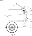
- FIG. 7 shows a variant of the agricultural machine for distributing product B for feeding animals and/or forming their litter.
- the door 2 and the complementary member 3 are each controlled by at least one respective cylinder.
- the door 2 is actuated by the at least one main cylinder 4 articulated in rotation, on the one hand on the box 1 around the third axis of rotation X3 and on the other hand on the door 2 around a fourth axis of rotation X4.
- the complementary member 3 is actuated by at least one complementary cylinder 6.
- the management device comprises on the one hand at least one complementary cylinder 6 distinct from the or each main cylinder 4 and articulated in rotation on the door 2 around a fifth axis of rotation X5 and on the complementary member 3 around a sixth axis of rotation X6, the actuation of the or each complementary cylinder 6 generating the rotation of the complementary member 3 relative to the door 2 and, on the other hand at least one control circuit 7 of the or each complementary cylinder 6.
- the figure 8 represents the control circuit of the complementary cylinder 6 connected to the control circuit of the main cylinder 4.
- the or each complementary jack 6 may comprise a body 60 articulated in rotation on the door 2, preferably on one of the sides 21 of the door 2, preferably on the external face of the side 21, around the fifth axis of rotation X5 and a rod 61 articulated in rotation at its end on the complementary member 3 around the sixth axis of rotation X6.
- the or each complementary cylinder 6 is a single-rod double-acting cylinder (equipped with a single rod 61) comprising a piston 64 connected to the rod 61 and separating two chambers 62, 63 containing a fluid under pressure, namely a small chamber 63 in which the rod 61 is located and a large chamber 62 on the opposite side.
- one or each control circuit 7 is configured so as to control the actuation of the or each complementary cylinder 6 as a function of the control pressure of the or each main cylinder 4.
- the control circuit 8 of the or each main cylinder 4 may comprise a distributor 80 with three slides, a first main line 81 connecting the large chamber 42 of the main cylinder 4 to the distributor 80 and a second main line 82 connecting the small chamber 43 to the distributor 80.
- the distributor 80 may comprise three positions, namely a rest position 800 (slide in central position), a first working position 801 (slide moved to the right as shown in the figure), a second working position 802 (slide moved to the right as shown in the figure), a third working position 803 (slide moved to the right as shown in the figure), a fourth working position 804 (slide moved to the right as shown in the figure), a fourth working position 805 (slide moved to the right as shown in the figure), a fourth working position 806 (slide moved to the right as shown in the figure), a fourth working position 807 (slide moved to the right as shown in the figure), a fourth working position 808 (slide moved to the right as shown in the figure
- the control circuit 7 of the or each cylinder 6 complementary may comprise a first additional line 70, a second additional line 71, a first pressure limiter 72 and a second pressure limiter 73.
- the first additional line 70 connects, via the first pressure limiter 72, the large chamber 62 of the complementary cylinder 6 to the first main line 81 and the second additional line 71 connects, via the second pressure limiter 73, the small chamber 63 to the second main line 82.
- the circuit (thin lines) comprising the second main 82 and additional 71 lines makes it possible to control the descent (movement towards the closed position) of the door 2 and at least several positions of the complementary member 3.
- the circuit (thick lines) comprising the first main 81 and additional 70 lines makes it possible to control the raising of the door 2 and at least several positions of the complementary member 3.
- the distributor 80 is controlled so as to send the oil under pressure, on the one hand, by means of the first main pipe 81, into the large chamber 42 of the main cylinder 4 (actuating the door 2) and, on the other hand, by means of the first additional pipe 70, into the large chamber 62 of the complementary cylinder 6. If the door 2 is empty (no product B loaded), the first pressure limiter 72 “blocks” the passage of the pressurized oil towards the large chamber 62 of the complementary cylinder 6 and the door 2 rises up to the upper stop, that is to say up against the threshold of the loading opening 10.
- the pressure in the first additional pipe 70 increases and the first pressure limiter 72 therefore “releases” the passage of the pressurized oil towards the large chamber 62 of the complementary cylinder 6, which has the effect of causing the rod 61 to come out and rotating the complementary member 3, thereby allowing it to fold.
- the distributor 80 is controlled so as to send the oil under pressure, on the one hand by means of the second main pipe 82 into the small chamber 43 of the main cylinder 4 and on the other hand by means of the second additional pipe 71 into the small chamber 63 of the complementary cylinder 6.
- the second pressure limiter 73 “blocks” the passage to the small chamber 63 of the complementary cylinder 6 and the door 2 descends (or opens) until it touches the ground S.
Landscapes
- Life Sciences & Earth Sciences (AREA)
- Environmental Sciences (AREA)
- Engineering & Computer Science (AREA)
- Mechanical Engineering (AREA)
- Soil Sciences (AREA)
- Closing And Opening Devices For Wings, And Checks For Wings (AREA)
- Feeding And Watering For Cattle Raising And Animal Husbandry (AREA)
Applications Claiming Priority (1)
| Application Number | Priority Date | Filing Date | Title |
|---|---|---|---|
| FR2308165A FR3151463B1 (fr) | 2023-07-28 | 2023-07-28 | Machine agricole de distribution de produit pour l’alimentation des animaux et/ou la formation de leur litière |
Publications (1)
| Publication Number | Publication Date |
|---|---|
| EP4497320A1 true EP4497320A1 (de) | 2025-01-29 |
Family
ID=88505011
Family Applications (1)
| Application Number | Title | Priority Date | Filing Date |
|---|---|---|---|
| EP24187956.8A Pending EP4497320A1 (de) | 2023-07-28 | 2024-07-11 | Landwirtschaftliche maschine zur verteilung eines produkts fur die fütterung von tieren und/oder die bildung von einstreu |
Country Status (3)
| Country | Link |
|---|---|
| US (1) | US12490663B2 (de) |
| EP (1) | EP4497320A1 (de) |
| FR (1) | FR3151463B1 (de) |
Citations (4)
| Publication number | Priority date | Publication date | Assignee | Title |
|---|---|---|---|---|
| US4619570A (en) * | 1982-03-30 | 1986-10-28 | Charles Siebenga | Bale loading-stacking apparatus |
| FR2773947A1 (fr) | 1998-01-27 | 1999-07-30 | Lucas Sa G | Dispositif d'aide au chargement d'une balle dans une benne de machine distributrice de paille ou fourrage |
| US20110014022A1 (en) * | 2009-07-15 | 2011-01-20 | John Shoemaker | System for Handling and Wrapping Large Bales |
| EP3440922B1 (de) * | 2017-08-09 | 2020-07-15 | Austrex Handels-Ges.m.b.h. | Ballentransportwagen |
Family Cites Families (10)
| Publication number | Priority date | Publication date | Assignee | Title |
|---|---|---|---|---|
| US2611579A (en) * | 1951-05-28 | 1952-09-23 | Miller Mfg Co Inc | Vehicle lift |
| US2981425A (en) * | 1958-08-08 | 1961-04-25 | Shell Oil Co | Loading device |
| US4082198A (en) * | 1976-02-02 | 1978-04-04 | Iowa State University Research Foundation, Inc. | Bale handling and shredding apparatus |
| US4930386A (en) * | 1987-12-10 | 1990-06-05 | Wood-Mizer Products, Inc. | Sawmill with hydraulically actuated components |
| US5397208A (en) * | 1988-03-11 | 1995-03-14 | Siebenga; Charles | Large bale handling apparatus |
| FR2645399B1 (fr) * | 1989-04-06 | 1992-02-14 | Dario Sa | Dispositif de chargement et de dechargement de balles cylindriques de paille ou de fourrage |
| US5340259A (en) * | 1992-11-24 | 1994-08-23 | Flaskey David L | Round bale handling trailer apparatus |
| JP3109994B2 (ja) * | 1996-09-25 | 2000-11-20 | 株式会社パブコ | 昇降装置の制御装置及び方法 |
| FR2789263B1 (fr) * | 1999-02-10 | 2001-03-09 | Calvet Ets | Derouleuse munie d'un dispositif de projection a turbine |
| AT511724B1 (de) * | 2012-01-05 | 2013-02-15 | Auer Landmaschb Ges M B H | Wagen mit einem ladegerät für silo-, heu- bzw. strohballen |
-
2023
- 2023-07-28 FR FR2308165A patent/FR3151463B1/fr active Active
-
2024
- 2024-07-11 EP EP24187956.8A patent/EP4497320A1/de active Pending
- 2024-07-26 US US18/786,144 patent/US12490663B2/en active Active
Patent Citations (4)
| Publication number | Priority date | Publication date | Assignee | Title |
|---|---|---|---|---|
| US4619570A (en) * | 1982-03-30 | 1986-10-28 | Charles Siebenga | Bale loading-stacking apparatus |
| FR2773947A1 (fr) | 1998-01-27 | 1999-07-30 | Lucas Sa G | Dispositif d'aide au chargement d'une balle dans une benne de machine distributrice de paille ou fourrage |
| US20110014022A1 (en) * | 2009-07-15 | 2011-01-20 | John Shoemaker | System for Handling and Wrapping Large Bales |
| EP3440922B1 (de) * | 2017-08-09 | 2020-07-15 | Austrex Handels-Ges.m.b.h. | Ballentransportwagen |
Also Published As
| Publication number | Publication date |
|---|---|
| FR3151463A1 (fr) | 2025-01-31 |
| US12490663B2 (en) | 2025-12-09 |
| FR3151463B1 (fr) | 2026-02-20 |
| US20250031597A1 (en) | 2025-01-30 |
Similar Documents
| Publication | Publication Date | Title |
|---|---|---|
| US4310275A (en) | Tilting platform hay bale accumulator | |
| EP0424192A1 (de) | Transportvorrichtung für Rundballen aus Futterpflanzen von einer Presse zu einem Anhänger | |
| FR2679410A1 (fr) | Porte balles aligneur groupeur. | |
| EP4497320A1 (de) | Landwirtschaftliche maschine zur verteilung eines produkts fur die fütterung von tieren und/oder die bildung von einstreu | |
| EP1075175B1 (de) | Rundballenpresse mit integrierter wickelvorrichtung | |
| EP0206889B1 (de) | Vorrichtung auf einer Rundballenpresse zum Auswerfen der Ballen | |
| FR2560488A1 (fr) | Remorque autochargeuse pour bottes de section carree ou rectangulaire | |
| EP0842597B1 (de) | Überziehen von gepresstem Gut mit einer Schlauchfolie | |
| FR2686480A1 (fr) | Materiel agricole pour la recolte de fruits portes par des arbres ou arbustes. | |
| FR2620300A1 (fr) | Procede de regroupement et de transport de balles cylindriques de vegetaux, et remorque attelee a un tracteur agricole pour la mise en oeuvre du procede | |
| EP4527649B1 (de) | Selbstschwenkende verlängerung für eine seitensperre einer transportplatte | |
| EP0761085B1 (de) | Ballenladewagen | |
| FR3050357A1 (fr) | Machine agricole de distribution d’un produit tel que du fourrage ou de la litiere et procede de chargement d’une telle machine | |
| FR3061409A1 (fr) | Melangeuse avec un dispositif de dechargement lateral | |
| EP1026935B1 (de) | Streckwerk für plastikhülle und maschine mit einem solchen streckwerk | |
| FR2743690A1 (fr) | Remorque auto-chargeuse de balles de paille | |
| FR2971392A1 (fr) | Dispositif de manutention de balles de vegetaux | |
| EP1950087A1 (de) | Verriegelungssystem für die Klappe einer abnehmbaren Ladungsmulde | |
| EP0035923B1 (de) | Auf einem Wagen gebautes Lade- und Entladegerät für Strohballen | |
| FR2466181A1 (fr) | Appareil mobile pour rassembler et empiler des balles de graminacees | |
| FR3135761A1 (fr) | Eperon d’attelage à une machine agricole | |
| EP4093194A1 (de) | Sprühgerät zum ausbringen von produkt(en) | |
| FR2768415A1 (fr) | Dispositif de convoyage et d'elevation d'articles pour le chargement d'un vehicule | |
| FR2773947A1 (fr) | Dispositif d'aide au chargement d'une balle dans une benne de machine distributrice de paille ou fourrage | |
| FR3068949A1 (fr) | Benne a porte de retenue |
Legal Events
| Date | Code | Title | Description |
|---|---|---|---|
| PUAI | Public reference made under article 153(3) epc to a published international application that has entered the european phase |
Free format text: ORIGINAL CODE: 0009012 |
|
| STAA | Information on the status of an ep patent application or granted ep patent |
Free format text: STATUS: THE APPLICATION HAS BEEN PUBLISHED |
|
| AK | Designated contracting states |
Kind code of ref document: A1 Designated state(s): AL AT BE BG CH CY CZ DE DK EE ES FI FR GB GR HR HU IE IS IT LI LT LU LV MC ME MK MT NL NO PL PT RO RS SE SI SK SM TR |
|
| STAA | Information on the status of an ep patent application or granted ep patent |
Free format text: STATUS: REQUEST FOR EXAMINATION WAS MADE |
|
| 17P | Request for examination filed |
Effective date: 20250729 |