EP4497344A1 - Système de support de pied milieu de chaussure - Google Patents
Système de support de pied milieu de chaussure Download PDFInfo
- Publication number
- EP4497344A1 EP4497344A1 EP24182125.5A EP24182125A EP4497344A1 EP 4497344 A1 EP4497344 A1 EP 4497344A1 EP 24182125 A EP24182125 A EP 24182125A EP 4497344 A1 EP4497344 A1 EP 4497344A1
- Authority
- EP
- European Patent Office
- Prior art keywords
- cases
- cable
- support
- foot
- lateral
- Prior art date
- Legal status (The legal status is an assumption and is not a legal conclusion. Google has not performed a legal analysis and makes no representation as to the accuracy of the status listed.)
- Granted
Links
Images


Classifications
-
- A—HUMAN NECESSITIES
- A43—FOOTWEAR
- A43B—CHARACTERISTIC FEATURES OF FOOTWEAR; PARTS OF FOOTWEAR
- A43B7/00—Footwear with health or hygienic arrangements
- A43B7/14—Footwear with health or hygienic arrangements with foot-supporting parts
- A43B7/1495—Footwear with health or hygienic arrangements with foot-supporting parts with arch-supports of the bracelet type
-
- A—HUMAN NECESSITIES
- A43—FOOTWEAR
- A43B—CHARACTERISTIC FEATURES OF FOOTWEAR; PARTS OF FOOTWEAR
- A43B23/00—Uppers; Boot legs; Stiffeners; Other single parts of footwear
- A43B23/02—Uppers; Boot legs
- A43B23/0245—Uppers; Boot legs characterised by the constructive form
- A43B23/0265—Uppers; Boot legs characterised by the constructive form having different properties in different directions
-
- A—HUMAN NECESSITIES
- A43—FOOTWEAR
- A43B—CHARACTERISTIC FEATURES OF FOOTWEAR; PARTS OF FOOTWEAR
- A43B23/00—Uppers; Boot legs; Stiffeners; Other single parts of footwear
- A43B23/22—Supports for the shank or arch of the uppers
- A43B23/227—Supports for the shank or arch of the uppers fixed on the outside of the shoe
-
- A—HUMAN NECESSITIES
- A43—FOOTWEAR
- A43B—CHARACTERISTIC FEATURES OF FOOTWEAR; PARTS OF FOOTWEAR
- A43B5/00—Footwear for sporting purposes
- A43B5/001—Golf shoes
-
- A—HUMAN NECESSITIES
- A43—FOOTWEAR
- A43B—CHARACTERISTIC FEATURES OF FOOTWEAR; PARTS OF FOOTWEAR
- A43B7/00—Footwear with health or hygienic arrangements
- A43B7/14—Footwear with health or hygienic arrangements with foot-supporting parts
- A43B7/1405—Footwear with health or hygienic arrangements with foot-supporting parts with pads or holes on one or more locations, or having an anatomical or curved form
- A43B7/1415—Footwear with health or hygienic arrangements with foot-supporting parts with pads or holes on one or more locations, or having an anatomical or curved form characterised by the location under the foot
- A43B7/1445—Footwear with health or hygienic arrangements with foot-supporting parts with pads or holes on one or more locations, or having an anatomical or curved form characterised by the location under the foot situated under the midfoot, i.e. the second, third or fourth metatarsal
-
- A—HUMAN NECESSITIES
- A43—FOOTWEAR
- A43C—FASTENINGS OR ATTACHMENTS OF FOOTWEAR; LACES IN GENERAL
- A43C11/00—Other fastenings specially adapted for shoes
- A43C11/16—Fastenings secured by wire, bolts, or the like
- A43C11/165—Fastenings secured by wire, bolts, or the like characterised by a spool, reel or pulley for winding up cables, laces or straps by rotation
Definitions
- the sport of golf involves a variety of actions that a golfer may perform, such as a golf swing, walking a golf course, crouching down to line-up a putt, and other golfing actions. Having proper equipment when playing the sport of golf may be a factor in how well the golfer may be able to perform these actions.
- Footwear i.e., shoes
- shoes are one example piece of equipment that can affect a golfer's performance. For example, when a golfer swings a club and transfers their weight on their feet, there are high forces placed on the golfer's foot.
- the shoe needs to provide a stable platform for the golfer when they make their swing, but the foot also needs to be able to flex to a certain degree. The bending of the shoe also is important when the golfer is walking, crouching down, and other golfing actions.
- footwear e.g., a golf shoe
- the midfoot support system may include a lateral strap extending from underfoot and over the midfoot region and a medial strap extending from underfoot inside the upper over the midfoot region.
- the medial strap extends outwardly from the upper material and is slidably engaged through the free end of the lateral strap.
- the free end of the medial strap may be engaged with an adjustable closure system to cinch the lateral and medial straps tightly around the midfoot.
- the lateral strap includes a rigid support structure.
- the midfoot support system allows the foot to be stabilized within the shoe reducing movement of the foot within the shoe. This additional stability and prevention of movement is helpful during the golf swing and shot taking.
- Examples include a golf shoe comprising: A golf shoe comprising: an upper; a sole connected to the upper at a bite line, the sole comprising an outsole and an insole, wherein the upper and sole each have a forefoot, midfoot, and heel regions, a lateral side, a medial side, an anterior end, and a posterior end; and a midfoot support system, comprising a lateral strap and a medial strap, wherein: the lateral strap is fixedly attached to the medial side of the outsole under a wearer's foot; the medial strap is fixedly attached to the lateral side of the insole under the wearer's foot; the lateral strap and the medial strap wrap around the wearer's foot and connect; tension of the midfoot support system can be increased and decreased; and when the tension of the midfoot support system is increased, the midfoot support system provides asymmetrical support of the wearer's foot by drawing the lateral side of the foot against the lateral side of the golf shoe.
- Examples further include a golf shoe comprising: an upper; a sole connected to the upper at a bite line; a lateral strap, wherein: the lateral strap comprises a first end fixedly attached to a medial side of the sole; the lateral strap is connected to the sole from its first end to a lateral side of the sole; from the lateral side of the sole, the lateral strap extends outward from the bite line and upwards along a lateral side of the upper and over at least a portion of a midfoot region of the upper to a second end; and the second end of the lateral strap comprises a ring; a medial strap, wherein: the medial strap comprises a first end fixedly attached to the lateral side of the sole; from its first end, the medial strap extends under a wearer's foot to the medial side of the sole and upwards along a medial surface of the midfoot region of the upper; and a second end of the medial strap extends from the upper, through the ring of the lateral strap, and towards an
- Examples further include a golf shoe comprising: an upper; a sole connected to the upper at a bite line; a lateral strap made from a first material, the lateral strap comprising: a first end attached at least along a portion of a medial side of the sole; a second end extending from the bite line and upwards over a lateral side of a midfoot region of the shoe; and a support structure, positioned within the lateral strap, made from a second material that is more rigid than the first material, the support structure comprising: a lower portion located proximate to the first end of the lateral strap extending to the lateral side of the sole; and an upper portion extending from the lateral side of the sole upwards along a portion of the lateral side of the upper; and a medial strap comprising: a first end attached to a lateral side of the sole; and a second end extending under a wearer's foot to the medial side of the sole, upwards along an interior surface on a medial side of a midfoot region
- the present disclosure provides an article of footwear comprising an upper; a sole assembly connected to the upper, wherein the sole assembly comprises a midsole and an outsole; an insole component configured to support a foot of a subject wearing the article of footwear; a support system comprising (i) a medial support extending under and along an inner surface of the upper, wherein the medial support includes (a) an elongated section that resists stretching in one or more directions and (b) a plurality of stretchable sections positioned along the elongated section, and (ii) a lateral support extending under the insole component and over or above the inner surface of the upper; and a securement system extending between the medial support and the lateral support.
- the securement system comprises: (i) a first cable configured to activate the medial and lateral supports to (a) pull the insole component up against a plantar surface of the foot and (b) draw the foot towards a lateral side of the upper, the sole assembly, or the insole component, and (ii) a second cable configured to (a) adjustably secure the upper around the foot and (b) pull the foot down and back towards a heel region of the upper, the sole assembly, or the insole component.
- the elongated section comprises a necked or tapered portion positioned at or near an arch region of the foot.
- the plurality of stretchable sections are directly adjacent to the necked or tapered portion.
- the plurality of stretchable sections are positioned on opposite sides of the necked or tapered portion.
- the plurality of stretchable sections comprise a multi-way stretch construction that conforms to a shape or a profile of an arch region of the foot.
- the plurality of stretchable sections comprise elastane.
- the elongated section is configured as a spinal structure or overlay that is substantially inelastic or inextensible in said one or more directions.
- the elongated section comprises a polyurethane (PU) or thermoplastic polyurethane (TPU).
- the elongated section comprises a fastener configured to engage one or more replaceable or interchangeable arch supports.
- the fastener is positioned in a necked or tapered portion of the elongated section between the plurality of stretchable sections.
- the article of footwear may further comprise one or more replaceable or interchangeable arch supports configured to accommodate a transverse arch shape or profile of the foot.
- the one or more replaceable or interchangeable arch supports are detachably coupled to the medial support.
- the medial support is detachably coupled to the insole component.
- the medial support comprises a first end that is detachably coupled to the insole component and a second end that extends around a medial side of the foot.
- the second end comprises a plurality of extensions that are looped or folded to engage the securement system.
- the lateral support comprises a flat plate. In some embodiments, the lateral support comprises a curved plate. In some embodiments, the lateral support comprises a composite plate. In some embodiments, the lateral support comprises a carbon fiber plate. In some embodiments, the lateral support may have a greater hardness, stiffness, and/or tensile strength than the upper.
- the lateral support is configured to extend under the insole component. In some embodiments, the lateral support is configured to extend to or from a bite line formed between the upper and the sole assembly.
- the lateral support is detached or decoupled from the upper and independently movable relative to the upper. In some embodiments, the lateral support is configured to translate along, over, or across the upper in response to a change in a level of tension in the securement system.
- the lateral support is positioned within a pocket or a sleeve that is integrated with the upper. In some embodiments, the lateral support is free floating and configured to move within the pocket or sleeve integrated with the upper.
- the lateral support comprises a slot.
- the slot is configured to receive a webbing material for connecting the lateral support to the securement system.
- the securement system may comprise a first cable and a second cable. In some embodiments, the first and second cables of the securement system are independently adjustable relative to each other.
- the article of footwear may comprise a shroud configured to separate the first cable and the second cable.
- the shroud is positioned between the first cable and the second cable to minimize interference between the first cable and the second cable.
- the article of footwear may comprise a side mounted dial configured to adjust or control the first cable. In some embodiments, the article of footwear may comprise a heel mounted dial configured to adjust or control the second cable.
- the present disclosure provides an article of footwear comprising: an upper; a sole assembly connected to the upper, wherein the sole assembly comprises a midsole and an outsole; an insole component configured to support a foot of a subject wearing the article of footwear, wherein the insole component comprises a footbed or an insole board; a support system comprising (i) a medial support extending under and along an inner surface of the upper and (ii) a lateral support extending under the insole component and over or above the inner surface of the upper; a securement system extending between the medial support and the lateral support, wherein the securement system comprises: (i) a first cable configured to (a) adjustably secure the upper around the foot and (b) pull the foot down and back towards a heel region of the upper, the sole assembly, or the insole component, and (ii) a second cable configured to activate the medial and lateral supports to (a) pull the insole component up against a plantar surface of the foot and (b) draw the foot towards a
- the first guide is positioned above, on top of, and/or over the second guide. In some embodiments, the second guide is positioned below or under the first guide. In some embodiments, the first guide may be formed by a first set of layers of the multi-layer construction, and the second guide may be formed by a second set of layers of the multi-layer construction. In some cases, the first and second set of layers may include one or more same layers of the multi-layer construction. In some cases, the first and second set of layers may include one or more different layers of the multi-layer construction.
- the multi-layer construction comprises a shroud or a panel positioned between the first cable and the second cable to separate the first and second cables. In some embodiments, the multi-layer construction comprises a first layer and a second layer attached or coupled to the first layer to form the first guide.
- the first guide corresponds to a path extending between detached portions or sections of the first and second layers.
- the first layer is configured to cover or conceal a portion of the first cable.
- the second layer is configured to cover or conceal a portion of the second cable.
- the article of footwear may comprise a third layer attached or coupled to the second layer to form the second guide.
- the second guide corresponds to a path extending between detached portions or sections of the second and third layers.
- the third layer is configured as a top cover for the tongue assembly.
- the article of footwear may comprise a fourth layer attached or coupled to the third layer to form a tongue assembly.
- the fourth layer is configured as an inner liner or lining for the tongue assembly.
- the article of footwear may comprise one or more multi-directional guides for controlling a position, an orientation, or a movement of the first cable.
- the one or more multi-directional guides include a housing with two or more channels extending through the housing in a plurality of different directions.
- the two or more channels may comprise a set of diagonal channels arranged in an X-shaped configuration.
- the article of footwear may comprise a sheath or a panel.
- the sheath or panel may extend across an instep region of the foot to cover or conceal a portion of the first cable and/or the second cable.
- the article of footwear may comprise a webbing overlay construction or a tongue overlay construction.
- the webbing overlay construction or a tongue overlay construction may be configured to guide or control a position, an orientation, or a movement of the first or second cable.
- the article of footwear may comprise a heel mounted dial configured to adjust or control the first cable and a side mounted dial configured to adjust or control the second cable.
- the side mounted dial is attached or coupled to the lateral support.
- the side mounted dial is configured to extend through the lateral support.
- the side mounted dial and the lateral support are configured to maintain a fixed spatial relationship as the side mounted dial is operated to engage or disengage the medial support or the lateral support.
- the lateral support and the side mounted dial may move synchronously along, across, or over the upper when the side mounted dial is operated to engage or disengage the medial support or the lateral support.
- any one or more aspects or features described with respect to one embodiment may be incorporated in a different embodiment although not specifically described relative thereto. That is, all embodiments and/or features of any embodiment can be combined in any way and/or combination. Applicant reserves the right to change any originally filed claim or file any new claim(s) accordingly, including the right to be able to amend any originally filed claim to depend from and/or incorporate any feature of any other claim although not originally claimed in that manner.
- a golf shoe comprising a midfoot support system that provides additional stability.
- the reinforcement structure may aid the shoe in being able to hold and support the medial and lateral sides of the golfer's foot as they shift their weight while making a golf shot.
- the golfer has a stable platform to drive power for a golf swing while being able to stay balanced during the follow through of the golf swing.
- the midfoot support system may provide stability for various types of biomechanical movements. For example, the biomechanics associated with swinging a golf club call for a rapid shift of weight from back foot to front foot.
- the midfoot support system of a pair of shoes when the midfoot support system of a pair of shoes is engaged, the wearer's feet remain further secured within their respective shoe and are prevented from shifting while swinging the golf club. Thus, the feet are also more easily planted in position when the midfoot support system is engaged.
- the midfoot support system stabilizes the trail foot by reducing abduction and external rotation. Reducing abduction and external rotation of the back foot enables the user to place more load on the back hip leg muscle thereby enabling increased separation between the hips and shoulders prior to the downswing.
- the midfoot support system may stabilize a desired portion of the foot for a variety of activities, and there is no intention to limit the usefulness of the current disclosure.
- the midfoot support system may stabilize at least a portion of a medial midfoot region for various activities.
- FIGURES 1A- 1E include various views depicting an example golf shoe 100, sometimes referred to herein generally as a shoe, in which aspects of a midfoot support system 111 may be implemented.
- Various views of an example midfoot support system 111 are further depicted in FIGURES 2 , 3 , 4A , and 4B .
- FIGURE 1A is a medial (e.g., inner) side view of the shoe 100 according to an example
- FIGURE 1B is a lateral (e.g., outer) side view of the of the shoe 100 according to an example
- FIGURE 1C is a rear view of the shoe 100 according to an example
- FIGURE 1D is a top view of the shoe 100 according to an example
- FIGURE 1E is a rear perspective view according to an example.
- the shoe 100 may generally include a shoe upper 104 and a sole 106.
- the shoe 100 includes a heel region 105, a midfoot region 135, a forefoot region 125, and the midfoot support system 111.
- the midfoot support system 111 includes a closure system (a first closure system 133).
- the shoe 100 includes a compound closure system including the first closure system 133 of the midfoot support system 111 and further including a second closure system 122.
- the heel region 105 may generally correspond with the rear portions of a wearer's foot, namely, the area surrounding and below the Achilles tendon, the posterior of the heel, and the talus and calcaneus bones.
- a forefoot region 125 may generally correspond with a front of the wearer's foot, namely, the toes and metatarsal, phalange, and sesamoid bones.
- the midfoot region 135 may generally correspond with a middle of the wearer's foot, namely, the arch and the navicular, cuboid, and cuneiform bones. It is understood that the heel region 105, midfoot region 135, and forefoot region 125 are intended to represent general areas of footwear and do not demarcate precise areas.
- the shoe 100 has a medial side that extends from the forefoot region 125 to the heel region 105 and a lateral side that extends from a forefoot region 125 to the heel region 105.
- the lateral side and the medial side may be opposite one another. In some examples, the lateral side and medial side may be generally parallel to one another.
- the lateral side generally corresponds to an outside area of the wearer's foot and a surface that faces away from a wearer's other foot.
- the medial side generally corresponds to an inside area of the wearer's foot and a surface that faces toward the wearer's other foot.
- the medial and lateral sides may apply to the shoe 100 in general, and the medial side and lateral side may apply to each of the upper 104, sole 106, and other associated areas in reference or relation to a general longitudinal centerline C of the shoe 100.
- the heel region 105 is considered to be a posterior end of the shoe 100, and, conversely, the forefoot region 125 is considered to be an anterior end of the shoe 100.
- the anterior end and posterior end may apply to the shoe 100 in general, and an anterior end and posterior end may apply to each of the upper 104, sole 106, and other associated areas in reference or relation to orientation toward the front or back of the shoe 100.
- the upper 104 may have an interior surface 145 (shown in FIGURE 1E ) and an exterior surface 155 (also shown in FIGURE 1E ).
- the interior surface 145 may partially define an area configured to receive a wearer's foot.
- the upper 104 may be configured to extend over the wearer's foot, along the medial and lateral sides of the foot, and around a forefoot region and a heel region of the foot.
- the area configured to receive the wearer's foot may be accessed from an ankle opening (herein referred to as a throat opening or throat 114), which is defined by a collar 118.
- the upper 104 includes an eye stay 107 in which eyelets may be defined and through which a lacing system may be threaded.
- a tongue 109 is included and is located under the eye stay 107 and lacing system. For instance, the tongue 109 may contact the top of the wearer's foot.
- the upper 104 may be constructed from any appropriate material now known or later developed, including, but not limited to, one or a combination of leather, suede, fabric, canvas, weaves, knits, man-made polymer fibers, nylon, polyester, or cotton.
- the upper 104 may be elastic.
- at least a portion of the upper 104 may be elastic.
- the upper 104 may be inelastic.
- at least a portion of the upper 104 may be inflexible and is rigid or semi-rigid.
- the upper 104 may further include a heel counter 103 at the heel region 105.
- the heel counter 103 may reinforce the upper 104 and limit movement of the wearer's heel.
- the heel counter 103 may wrap around the heel region 105 and extend forward along both the lateral side and the medial side of the shoe 100.
- the sole 106 may include an outsole 116, a midsole 115, and an insole 117 (shown in FIGURES 1D and 1E ).
- the sole 106 may be coupled to the upper 104 at a bite line 165.
- the sole 106 may be configured to attenuate forces or provide support or cushioning.
- the midsole 115 may be formed from a compressible material that provides cushioning.
- the midsole 115 may include a structural support structure or be formed from dense materials to increase stability.
- the outsole 116 may be below the midsole 115 and designed to interact with a ground surface.
- the outsole 116 may be designed to impart traction.
- traction members 175 e.g., spikes, cleats, or other devices for additional traction
- Such traction members 175 may be releasably coupled to the outsole 116.
- such traction members 175 may be fixedly coupled to the outsole 116.
- the outsole 116 may be include multiple pads or ridges.
- the insole 117 may be designed to provide cushioning or comfort for the wearer.
- the insole 117 may be removable and may be above the midsole 115 when in use.
- the insole 117 may be designed to provide support.
- the insole 117 may be flexible, semi-rigid, or rigid.
- the midfoot support system 111 may be utilized at least in part to secure the upper 104 around the wearer's foot by pulling up slack of material of the upper 104 and surrounding and compressing around the wearer's foot to anchor the foot against a lateral edge of the shoe 100.
- the midfoot support system 111 further includes two adjustment straps: a lateral strap 108 (shown in FIGURES 1B , 1D , 1E , 2 , 4A and 4B ) and a medial strap 110 (shown in FIGURES 1A , 1D , 1E , 2 , 4A and 4B ).
- the lateral strap 108 and the medial strap 110 may be formed from one or a combination of materials, such as leather, suede, fabric, canvas, weaves, knits, man-made polymer fibers, nylon, polyester, cotton, carbon fiber, thermosets, thermoplastics, or any appropriate material now known or later developed.
- the lateral strap 108 is fixedly attached to the sole 106 (e.g., between the midsole 115 and the insole 117 of the sole 106).
- a first end of the lateral strap 108 which is referred to herein as a connected end 128, may be connected at or proximate to a medial edge of the insole 117 and/or the midsole 115. From its connected end 128, the lateral strap 108 may extend under the medial-lateral width of the midfoot region 135 to the lateral side of the bite line 165.
- the lateral strap 108 may be fixedly attached to the insole 117 and/or midsole 115 along the entire medial-lateral width or substantially the entire medial-lateral width of the insole 117 and/or midsole 115. In other examples, the lateral strap 108 may be fixedly attached to the insole 117 and/or midsole 115 along only the medial edge of the insole 117 and/or midsole 115. In further examples, a portion of the lateral strap 108 may be recessed into the midsole 115.
- the lateral strap 108 may further extend upwardly, from the bite line 165 on the lateral side of the shoe 100, along the outer lateral side of the upper 104, and over at least a portion of the midfoot region 135 of the upper 104.
- the connected end 128 of the lateral strap 108 is attached to the insole 117 or the midsole 115 by stitching, adhesives, or other suitable means and techniques to fixedly attach the lateral strap 108.
- the lateral strap 108 further includes a second end, which is referred to herein as a free end 131, that is configured to engage the medial strap 110.
- this engagement allows for a cinching and pulling of the lateral side of the wearer's foot against the lateral side of the shoe 100 to reduce movement and improve stability.
- This asymmetry in the shoe 100 is desirable in the sport of golf.
- securing the wearer's foot against the lateral edge of the shoe 100 is ideal for swinging a golf club, where lateral stability is advantageous to efficacy and quality of a golf swing.
- a first end of the medial strap 110 which is referred to herein as a connected end 138, is anchored to the shoe 100 at an anchor point under the lateral side of the wearer's foot.
- the anchor point of the medial strap 110 may be located along the lateral side of the insole 117 or the midsole 115.
- the anchor point of the medial strap 110 may be at or proximate to a lateral edge of the insole 117 or the midsole 115 (e.g., at or proximate to the bite line 165).
- the connected end 138 of the medial strap 110 is attached to the insole 117 or the midsole 115 by stitching, adhesives, or other suitable means and techniques to anchor the medial strap 110.
- the medial strap 110 may extend under the midfoot region 135, traversing medially across the wearer's arch on the medial side of the insole 117 or midsole 115 and wrapping upwards along the wearer's arc on the medial side and continuing across the wearer's instep (e.g., upper portion of the middle foot) and upwardly along the medial side of the upper 104 for connection with the lateral strap 108.
- the medial strap 110 is fixedly attached to the shoe 100 only at the lateral edge of the insole 117 or the midsole 115, where the portion of the medial strap 110 that extends under the midfoot region 135 may be free-floating.
- the medial strap 110 may wrap upwardly along the inner medial side of the upper 104 and then outwardly from the upper 104 for connection with the lateral strap 108. In other examples, the medial strap 110 may extend from the bite line 165 on the medial side of the shoe 100 and upwards along on the outer medial side of the upper 104 for connection with the lateral strap 108. According to examples, tension applied to the medial strap 110 causes the medial strap 110 to pull around the wearer's foot and up against the wearer's arch.
- the midfoot support system 111 provides 360-degree adjustment of the wearer's foot inside the shoe 100, allowing for adjustments geared toward the asymmetry of support advantageous for golf (e.g., securing the wearer's foot against the lateral side of the shoe 100).
- the 360-degree adjustment may include cinching and pulling the wearer's foot against the lateral side of the shoe 100, reducing movement of the foot and improving stability.
- movement of the wearer's foot within the shoe 100 may be reduced by 5-6mm.
- the midfoot support system 111 may be configured to allow for adjustments geared toward a different asymmetry (e.g., securing the wearer's foot against the medial side of the shoe 100).
- a second end of the medial strap 110 which is referred to herein as a free end 141, may be slidably received through at least one ring 123a,123b (collectively, rings 123) defined in or attached to the free end 131 of the lateral strap 108.
- Each ring 123 may be sized to receive at least a portion of the medial strap 110 through an opening, allow it to pass through the ring 123, and double-back on itself.
- the free end 141 of the medial strap may be engaged by the first closure system 133.
- the first closure system 133 can include one of various types of closure systems operative to engage the free end 141 of the medial strap 110 and apply tension to pull the medial strap 110 toward the medial side of the shoe 100. For example, when tension is applied and the free end 141 of the medial strap 110 is pulled, the medial strap 110 engages the lateral strap 108 and produces a cinching action that stabilizes a region of the shoe 100 and distributes the applied pressure over a desired area of the shoe 100.
- first closure system 133 is depicted in FIGURES 1A- 1D and described below as an adjustable lacing system (e.g., a BOA closure system of BOA Technology, Inc. described in U.S. Pat No. 10,070,695 , and incorporated herein by reference in its entirety), in other examples, the first closure system 133 may be implemented using another type of closure system, such as laces, buckles, ratchets, hook and loop fasteners, or other systems.
- adjustable lacing system e.g., a BOA closure system of BOA Technology, Inc. described in U.S. Pat No. 10,070,695 , and incorporated herein by reference in its entirety
- the first closure system 133 may be implemented using another type of closure system, such as laces, buckles, ratchets, hook and loop fasteners, or other systems.
- the first closure system 133 may be configured to apply a pulling force to the medial strap 110 toward the medial side of the shoe 100.
- the medial strap 110 may be engaged by the first closure system 133 on the lateral side of the shoe 100.
- a first hole or slit 137 may be defined in the free end 141 of the medial strap 110.
- the first slit 137 splits a portion of the medial strap 110 into an anterior sub-strap 112 and a posterior sub-strap 113.
- the anterior sub-strap 112 and posterior sub-strap 113 of the medial strap 110 may be configured to move independently from one another to a degree in response to different pulling forces when the medial strap 110 is engaged.
- a lace receiving element 121 may be defined in or attached to the free end 141 of each of the anterior sub-strap 112 and the posterior sub-strap 113.
- the lace receiving elements 121 may be sized to receive a first lace 152 of the first closure system 133 through an opening and allow the first lace 152 to pass through the lace receiving elements 121.
- the openings of the lace receiving elements 121 are low friction.
- a portion of the first lace 152 may be above the upper 104 and configured to interact with the outer surface of the upper 104.
- the lace receiving elements 121 of the medial strap 110 may be configured to prevent the first lace 152 from being in direct contact with the upper 104 at the position of the lace receiving elements.
- a second slit 127 may be defined in the free end 131 of the lateral strap 108.
- the second slit 127 splits a portion of the lateral strap 108 into an anterior extension 142 and a posterior extension 143.
- the anterior extension 142 and the posterior extension 143 of the lateral strap 108 may be configured to move independently from one another to a degree in response to different pulling forces and pull angles caused in part by engagement, at the rings 123, with the anterior sub-strap 112 and posterior sub-strap 113 of the medial strap 110.
- the lateral strap 108 may be of various shapes. According to one example, the connected end 128 of the lateral strap 108 may be shaped in a general contour of a middle of a foot, namely, the arch. In some examples, the lateral strap 108 may include two rings 123 that are configured to receive and allow the anterior sub-strap 112 and the posterior sub-strap 113 of the medial strap 110 to pass through. In some examples, each of the anterior sub-strap 112 and posterior sub-strap 113 may be received from a bottom side of the ring 123 and fold transversely of its length and back on itself to attach to the first closure system 133.
- the rings 123 are shown as being positioned substantially above the throat of the shoe 100 when the first closure system 133 is at low or no tension.
- the lengths of the lateral strap 108 and the medial strap 110 may be differently configured such that the rings 123 are positioned at different locations about the shoe 100.
- the lateral strap 108 may have a shorter length than depicted, and the rings 123 may be positioned more on the lateral side of the shoe 100. Positioning the rings 123 in such a manner changes the closure or pulling force directions when the medial strap 110 is tightened. For instance, the pulling forces may be more vertical.
- the lateral strap 108 may be longer than depicted and the rings 123 may be positioned on a medial side of the shoe 100. This different position also changes the pulling forces.
- the first closure system 133 may include the first lace 152 mentioned above, a first adjustable dial 154, and first lace guides 156. In other examples, the first closure system 133 may not utilize the first adjustable dial 154 to control the tension of the first lace 152, and the tension may be increased, decreased, and/or secured by other means, such as a tied lace, an elasticized lace, a buckle, a ratchet, a hook and loop fastener, or other ways now known or later developed. Increasing the tension may result in a tightening of the first lace 152 and decreasing the tension may result in a loosening of the first lace 152. In some examples, the first lace 152 may be a tensile lace. In other examples, the first lace 152 may be a wire.
- the first lace guides 156 may be coupled to the upper 104 at positions that enable the wearer to secure the upper 104 to their foot.
- the first lace guides 156 may be strategically placed such that when tightened, the first lace 152 does not cause a user discomfort.
- the placement of the first lace guides 156 may assist in stabilizing the foot.
- the first closure system 133 and placement of the first lace guides 156 may attenuate forces acting on the wearer's foot, such as pressure, shear force, ground forces, or the ability for flexion or movement.
- the first lace guides 156 may be openings that allow the first lace 152 to slide through the opening when tension is increased or decreased, for example, using the first adjustable dial 154.
- the first lace guides 156 are low friction.
- the interior surfaces of the first lace guides 156 that contact the first lace 152 may be made from a lower friction material than the outer surfaces that do not contact the first lace 152.
- the first lace guides 156 may be attached to the shoe 100 on the medial side of the upper 104.
- the first lace guides 156 are located between the eye stay 107 and the bite line 165.
- the first lace 152 may be coupled at a first end to a lace anchor 158 and at a second end to the first adjustable dial 154.
- the lace anchor 158 may be coupled to the shoe 100 at or proximate the eye stay 107.
- the lace anchor 158 is located on the anterior-medial side of the eye stay 107.
- the lace anchor 158 is fixedly coupled to the shoe 100.
- the first lace guides 156 may be generally located along the medial side of the upper 104 to guide the first lace 152 posteriorly to the first adjustable dial 154.
- the first lace guides 156 may be positioned, such that when the first lace 152 is tightened, the increased tension of the first lace 152 exerts a pulling force on the free end 141 of the medial strap 110 (e.g., the free ends of the anterior sub-strap 112 and the posterior sub-strap 113).
- the medial strap 110 is engaged with the free end 131 of the lateral strap 108, wraps around the wearer's arch, and is anchored to the lateral edge of the shoe 100 below the wearer's foot. Additionally, in some examples, the medial strap 110 may only be attached at the lateral edge of the bite line 165, where the remainder of the medial strap 110 may be free-floating.
- the medial strap 110 may be pulled around the wearer's foot and up against the arch of the foot. Additionally, the lateral strap 108 wraps below the wearer's foot and is attached to the upper surface of the midsole 115 of the shoe 100. Thus, increased tension of the first lace 152 may cause increased tension in the medial strap 110, and further cause the medial strap 110 to engage and pull the lateral strap 108 inwardly toward the medial side of the shoe 100 and tightly around the midfoot region 135 to secure the upper 104 around the wearer's foot. In some examples, engaging the lateral strap 108 prevents the foot from linearly sliding media-laterally within the shoe 100.
- the pulling force applied to the medial strap 110 by the first closure system 133 may cause the midfoot support system 111 to compress around the wearer's foot and further cause the midfoot support system 111 to index the lateral strap 108 against the wearer's foot, which may anchor the wearer's foot against a lateral edge of the shoe 100 for stabilizing and reducing horizontal movement of the foot.
- the lateral strap 108 includes a support structure 102 to increase lateral support and stability of the midfoot support system 111.
- a first pull force vector may be applied inside the shoe 100 that manipulates the wearer's foot to the lateral side of the upper 104, and a second pull force vector may cross the first pull force vector.
- the second pull force vector may be applied on the outside of the lateral side of the wearer's foot by a rigid support structure 102.
- the pulling force applied to the medial strap 110 may further cause the midfoot support system 111 to take up slack and airspace under the wearer's foot by drawing the insole 117 against the foot.
- the pulling force may cause the midfoot support system 111 to take up air space or volume within the shoe 100.
- Some volume may be due in part to an enlarged throat 114 opening to facilitate placement of a foot within the upper 104 of the shoe 100.
- some shoes 100 have increased volume due in part to increased widths to accommodate for wider foot sizes.
- a portion of the first lace 152 may be above the upper 104 and configured to interact with the outer surface of the upper 104.
- the first lace guides 156 may be placed such that the first lace 152 is not in direct contact with the upper 104.
- the first lace 152 may be at least partially visible.
- a portion of the first lace 152 may be between an exterior surface of the upper 104 and an interior surface of the upper 104. In such embodiments there may be a channel for the laces between the exterior and the interior surfaces of the upper 104. The exterior and the interior surfaces of the upper 104.
- the first adjustable dial 154 may be at the posterior end of the shoe 100 at the heel region 105. In some examples, the first adjustable dial 154 may be generally halfway between the collar 118 and the bite line 165.
- the first lace 152 may be attached at the lace anchor 158 and be slidably received through a first-first lace guide 156.
- the first-first lace guide 156 may be located below and posterior to the lace anchor 158.
- the first lace 152 may be further slidably received through a first lace receiving element 121 located on the anterior sub-strap 112 of the medial strap 110.
- the first lace receiving element 121 may be located above and posterior to the first lace guide 156.
- the lace 152 may be further slidably received through a second first lace guide 156.
- the second first lace guide 156 may be located posterior to the first-first lace guide 156.
- the second first lace guide 156 may be located above the first-first lace guide 156 and below the first lace receiving element 121.
- the first lace 152 may be further slidably received through a second lace receiving element 121 located on the posterior sub-strap 113 of the medial strap 110.
- the second lace receiving element 121 may be located above and posterior to the first lace receiving element 121.
- the first lace 152 may be further slidably received through a third first lace guide 156 located posterior to the second first lace guide 156.
- the third first lace guide 156 may be located above the second first lace guide 156 and below the second lace receiving element 121.
- the first lace 152 may further be attached at its second end to the first adjustable dial 154.
- the positions of the first lace guides 156 and lace anchor 158 may vary.
- the tensions on the posterior sub-strap 113 and the anterior sub-strap 112 may be separately controlled or adjusted through an additional tension adjustment element (not depicted).
- a first adjustment element is provided for adjusting the tension on the posterior sub-strap 113 and a second adjustment element is provided for adjusting the tension on the anterior sub-strap 112.
- the adjustment elements may be the same type or different types.
- the adjustable dial 154 may be used to adjust tension on one sub-strap, and a second type of adjustment element may be used to adjust tension on the other sub-strap.
- a first ratchet may be used for adjusting tension on the anterior sub-strap 112 and a second ratchet may be used for adjusting tension on the posterior sub-strap 113.
- one of the posterior sub-strap 113 and the anterior sub-strap 112 may be fixed to the outer/exterior surface 155 of the upper 104 and tension may be adjusted for the other sub-strap.
- the fixed sub- strap may be at least partially elastic to assist in the golfer putting on the shoe 100.
- the lateral strap 108 may include a support structure 102.
- the support structure 102 may be rigid or semi-rigid.
- the support structure 102 is more rigid than the material used for lateral strap 108.
- the amount of stabilization provided by the support structure 102 may vary depending on its rigidity, wherein increased rigidity may provide higher stabilization effects.
- the support structure 102 is fixedly attached to the sole 106 (e.g., to the midsole 115) and is generally L-shaped.
- the support structure 102 may be located within the lateral strap 108 such that a lower portion 164 of the support structure 102 may be located at or proximate to the connected end 128 of the lateral strap 108 and extend under the midfoot region 135 and to the lateral edge of the insole 117, where it then extends upward along a portion of the outer lateral side of the upper 104.
- the upper portion 162 of the support structure 102 is curved inwardly toward the medial side of the shoe 100.
- the inward curve of the upper portion 162 of the support structure 102 may be shaped so as to generally fit a contour of the outer lateral side of a wearer's midfoot.
- the support structure 102 may have a width that is generally uniform throughout the support structure 102. Alternately, the support structure 102 may have a variable width to provide increased stability. In some examples, the width of the support structure 102 may be wider proximate the bite line 165 and taper as it extends toward an uppermost point of the upper portion 162. According to examples, the support structure 102 may provide a higher level of rigidity to the lateral strap 108, and therefore to the midfoot support system 111 and the shoe 100. For example, when the midfoot support system 111 is engaged and the wearer is taking a stance, the wearer's feet may be anchored and locked in against the rigid lower portion 164 and upper portion 162 of the support structure 102.
- the support structure 102 may be formed from carbon fiber, thermosets, thermoplastics, or any appropriate material now known or later developed with suitable rigidity.
- the support structure 102 comprises a self-reinforced polymer composite material.
- Self-reinforced polymer composites are generally known in the composite industry and refer to fiber- reinforced composites comprising reinforcing fibers and a polymer matrix, where the highly oriented reinforcing fibers are made from the same polymer in which the matrix is made.
- a polypropylene matrix can be reinforced with polypropylene fibers.
- the support structure 102 may be pre-molded into one of various sizes and shapes. For example, one or a combination of the width, length of the lower portion 164, and the height and curvature of the upper portion 162 of the support structure 102 may vary based on a shoe size, whether the shoe 100 is designed for a male, female, or youth foot, whether the shoe 100 is designed for a narrow, regular, or wide foot, and other factors. In some examples, the curvature of the upper portion 162 of the support structure 102 may be custom fit/molded to a wearer's foot. In some examples, the support structure 102 may be made of a heat moldable or thermoformable material that allows a wearer to custom-fit or mold the support structure 102 to the wearer's foot post-purchase.
- the support structure 102 may be attached to the lateral strap 108 by stitching, adhesives, or other suitable means and techniques to incorporate the support structure 102 into the lateral strap 108.
- the support structure 102 may be further attached to the midsole 115 by adhesives, insert molding, or another suitable means and technique to attach the support structure 102 to the midsole 115.
- the medial strap 110 may include a low-friction material disposed on at least a back side 167 of the anterior sub-strap 112 and posterior sub-strap 113 of the medial strap 110 to improve sliding movement of the medial strap 110 when the first lace 152 of the first closure system 133 is being tightened.
- the low-friction material may allow the medial strap 110 to slide against the outer surface 155 of the upper 104 to prevent the outer surface material from bunching and causing discomfort to the wearer.
- the medial strap 110 and the lateral strap 108 may be cinched and secured to the upper 104 in an engaged position. This may provide increased lateral stability.
- the medial strap 110 and/or the lateral strap 108 may arc laterally outward from the upper 104.
- the shoe 100 may include a second closure system 122 that may further secure a wearer's foot within the upper 104.
- the second closure system 122 may be proximate the eye stay 107 as can be seen in FIGURES 1A , 1B , and 1D .
- the second closure system 122 may be utilized at least in part to secure the upper 104 around the wearer's foot by controlling closure of the throat 114 around the wearer's foot.
- the second closure system 122 may enable the throat 114 opening to be enlarged to facilitate placement of a wearer's foot within the upper 104 of the shoe 100 and then to be closed around the wearer's foot.
- the second closure system 122 may sometimes referred to herein as a throat closure system.
- the second closure system 122 is implemented as an adjustable lacing system, such as a BOA closure system as described above.
- the shoe 100 may include two adjustable lacing systems, where the first closure system 133 is a first adjustable lacing system and the second closure system 122 is a second adjustable lacing system.
- the second closure system 122 may include an adjustable lacing system that uses at least one lace (e.g., second lace 172) an adjustable dial (e.g., second adjustable dial 174), and lace guides (e.g., second lace guides 176).
- the second lace 172 may be selectively adjusted using the second adjustable dial 174. Increasing the tension may result in a tightening of the second lace 172 and decreasing the tension may result in a loosening of the second lace 172.
- the tension of the second lace 172 may be decreased using the second adjustable dial 174 to allow a wearer to place their foot at least partially within the upper 104.
- the wearer may use the second adjustable dial 174 to increase tension to the second lace 172 in order to tighten the second lace 172 and secure the upper 104 around the wearer's foot.
- the second lace 172 may be secured in any way now known or later developed.
- the second lace 172 may be secured by tying ends of the second lace 172 to one another.
- the second lace 172 may be a tensile lace.
- the second lace 172 is a wire. When a tension of the second lace 172 is increased, the second lace 172 may aid in securing the upper 104 around the wearer's foot.
- the second lace guides 176 may be loops that allow the second lace 172 to slide through the loop when tension is increased or decreased using the second adjustable dial 174. In some examples, the second lace guides 176 are low friction. The second lace guides 176 may be coupled to the upper 104 at strategic points to help secure the upper 104 to the wearer's foot. The second lace guides 176 may be strategically placed such that when tightened, the second lace 172 does not cause the wearer discomfort. The placement of the second lace guides 176 may assist in stabilizing the foot. In some examples, the second closure system 122 and placement of the second lace guides 176 may attenuate forces acting on a wearer's foot such as pressure, shear force, ground forces, or the ability for flexion or movement.
- the second lace 172 may be above the upper 104 and configured to interact with an outer/exterior surface 155 of the upper 104, such as the outer/exterior surface of the eye stay 107.
- the second lace 172 may be entirely or partially visible.
- the second lace 172 may be between exterior surface 155 of the upper 104 and the interior surface 145 of the upper 104.
- the second lace guides 176 may also be positioned between the exterior surface 155 of the upper 104 and the interior surface 145 of the upper 104.
- a portion of the second lace 172 may be between the exterior surface 155 of the upper 104 and the interior surface 145 of the upper 104, and another portion of the second lace 172 may be above the exterior surface 155 of the upper 104.
- the upper 104 may optionally have grooves (not shown herein) for facilitating the placement of the second lace 172 when the second adjustable dial 174 is tightened.
- the grooves may secure the second lace 172 when the second adjustable dial 174 is tightened and prevent the second lace 172 from slipping or being tightened at an undesired location that may affect forces acting on the shoe 100 or a wearer's foot.
- the grooves may also provide a reliable position for the second lace 172 such that a wearer would not need to readjust the second lace 172.
- the second adjustable dial 174 may be coupled to the upper 104 proximate the eye stay 107. As depicted in FIGURES 1A , 1B , and 1D , in some examples, the second adjustable dial 174 may be coupled to the tongue 109. In other examples, the second adjustable dial 174 may be coupled to the upper 104 at an anterior side, medial side, or lateral side of the eye stay 107.
- At least one second lace guide 176 may be attached to or proximate the eye stay 107.
- at least one second lace guide 176 may be attached to or proximate a medial side of the eye stay 107, and at least one second lace guide 176 may be attached to or proximate a lateral side of the eye stay 107.
- another second lace guide 176 may be attached to or proximate an anterior side of the eye stay 107.
- the second lace 172 may be coupled at both ends to the second adjustable dial 174.
- the second closure system 122 may include a variety of alternative fastening mechanisms, such as a tied lace, an elasticized lace, a band with a hook and loop closure, an elastic buckle, a button, a hook, a snap, or any other fastening device now known or later developed. It will be further appreciated that in further examples, the shoe 100 may not include a second closure system 122.
- the medial strap 110 may extend medially under the midfoot region 135 below the insole 117, and upward along the outer/exterior surface 155 of the medial side of the upper 104 for engagement with the lateral strap 108 and further engagement with the first closure system 133.
- the medial strap 110 may be configured to interact with the outer surface of the upper 104 from the bite line 165. This may allow for the free end of the lateral strap 108 to be pulled inwardly toward the medial side of the shoe 100, over the top of the midfoot region 135, and downward over the medial side of the upper 104.
- the angles at which the pull force of the lateral strap 108 are directed may be modified.
- the present disclosure provides an article of footwear configured to adapt to a shape or a profile of a subject's foot.
- the article of footwear may be configured to conform to a shape or a profile of an arch region of a subject's foot in order to provide a 360 degree fit around the subject's foot.
- the article of footwear may be configured to control a position and/or a movement a subject's foot within the shoe or relative to the shoe (e.g., during a golf-related action).
- the article of footwear may be configurable or adjustable to (i) secure a subject's foot down and back towards the heel while simultaneously (ii) pulling the insole up against the plantar surface of the foot and (iii) placing the lateral edge of the foot against the lateral edge of the article of footwear.
- the article of footwear may be configured to minimize the relative motion of a subject's foot within the article of footwear (e.g., during a golf swing) and provide a confident locked down feel that can add power and control to a subject's golf swing.
- the article of footwear may comprise a shoe 500 with an upper and a sole assembly connected to the upper, as described in detail above.
- the sole assembly may comprise a midsole and an outsole as described elsewhere herein.
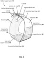
- the article of footwear may comprise an insole component 510 configured to support a foot of a subject wearing the article of footwear.
- the insole component 510 may comprise an insole board or a footbed.
- the insole component 510 may be designed to provide support for a subject's foot (e.g., as the subject exerts a force on the insole while walking, running, kneeling, squatting, or executing a swing).
- the insole component 510 may be flexible, semi-rigid, or rigid.
- the insole component 510 may be a removable insert that can be positioned within the shoe 100.
- the insole component 510 can be designed to provide cushioning or comfort for the subject wearing the shoe 100.
- the article of footwear may comprise a support system.
- the support system may comprise (i) a medial support extending under and along an inner surface of the upper and (ii) a lateral support extending under the insole component and over or above the inner surface of the upper.
- the inner surface of the upper may correspond to a surface region of the upper that faces inwards towards a subject's foot. In some cases, the inner surface of the upper may correspond to a surface region of the upper that is directly adjacent to a subject's foot. In some cases, the inner surface of the upper may correspond to a surface region of the upper that can directly or indirectly contact a portion of a subject's foot.
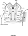
- the shoe 500 may comprise a support system comprising a medial support 520.
- the medial support 520 may be detachably coupled to the insole component 510.
- the medial support 520 may comprise a first end 521 that can be detachably coupled to the insole component 510 and a second end 522 that can extend around or along a medial side of the foot.
- the second end 522 may comprise one or more extensions 540 that are looped or folded to engage a securement system (e.g., as described in further detail below).
- the second end 522 may comprise one or more extensions 540 with fixed length loops.
- the fixed length loops may comprise a looped end formed of a single continuous piece of material.
- the single continuous piece of material may be undetachably secured to itself to form the fixed length looped end.
- the size and/or shape of the fixed length looped end may not or need not be adjustable.
- the medial support 520 may be optimized to provide an even compression of the midfoot/arch.
- the height, width, or length of the medial support 520 may be adjustable based on the shape or dimensions of a subject's foot. In other cases, the height, width, and/or length of the medial support 520 may be fixed to maintain a lower profile that does not interfere with the throat closure.
- the medial support 520 may be interchanged or replaced with another medial support having the proper shape, profile, and/or dimensions to conform to a particular subject's foot.
- the medial support 520 may be configured to adjust or conform to a shape or a profile of a subject's foot. In some embodiments, the medial support 520 may be configured to accommodate an arch height, width, and/or length of a subject's foot.
- the medial support 520 may include an elongated section 525 that resists stretching in one or more directions.
- the medial support 520 may include a plurality of stretchable sections 530 positioned along the elongated section 525.
- the elongated section 525 may comprise a piece, a panel, or a layer of material that extends between a first location under a subject's foot and a second location on a side or top portion of the subject's foot.
- the elongated section 525 may have a first end 521 that can be detachably coupled to the insole component 510 at or near the first location, and a second end 522 that can be positioned at or near the second location.
- the elongated section 525 may be configured to extend around the medial side of a subject's foot between the first location and the second location.
- a portion of the elongated section 525 may be configured to extend under and/or along an inner surface of the upper (i.e., a surface of the upper that faces inwards towards a subject's foot).
- the elongated section 525 may comprise a necked or tapered portion 515.
- the necked or tapered portion 515 may be configured to accommodate a shape or a profile of a subject's longitudinal arch.
- the necked or tapered portion 515 may be located between the first end 521 and the second end 522 of the elongated section 525.
- the necked or tapered portion 515 may be positionable at or near an arch region of a subject's foot.
- the width of the elongated section 525 at the necked or tapered portion may be less than a width of one or more other portions of the elongated section 525. In some cases, the width of the elongated section 525 at the necked or tapered portion may be less than a width of a first end 521 or a second end 522 of the elongated section 525. In some cases, the width of the elongated section 525 may gradually increase from the necked or tapered portion towards the first end 521 or the second end 522 of the elongated section 525.
- the width of the elongated section 525 may increase from the necked or tapered portion towards the first end 521 of the elongated section 525 at a first rate (i.e., a first rate of change in width per unit distance or length in the longitudinal direction). In some cases, the width of the elongated section 525 may increase from the necked or tapered portion towards the second end 522 of the elongated section 525 at a second rate (i.e., a second rate of change in width per unit distance or length in the longitudinal direction). In some cases, the first rate and the second rate may be the same. In other cases, the first rate and the second rate may be different. In some cases, the first rate may be greater than the second rate. In other cases, the second rate may be greater than the first rate.
- the elongated section 525 may be configured as a spinal structure or overlay that is substantially inelastic or inextensible in one or more directions.
- the spinal structure or overlay may be configured to support the medial side of a subject's foot (e.g., when the subject is executing a golf-related action or movement).
- the elongated section 525 may be configured to resist stretching or deformation in or along one or more directions.
- the elongated section 525 may comprise a polyurethane (PU) or thermoplastic polyurethane (TPU) material.
- the elongated section 525 may comprise a hotmelt TPU material.
- the plurality of stretchable sections 530 may be directly adjacent to the necked or tapered portion 515 of the medial support 520.
- the plurality of stretchable sections 530 may be configured to conform to and support a subject's arch in the anteroposterior direction.
- the plurality of stretchable sections 530 may be positioned on opposite sides of the necked or tapered portion 515 of the elongated section 525.
- the plurality of stretchable sections 530 may comprise a multi-way stretch construction that conforms to a shape or a profile of an arch region of the foot.
- the multi-way stretch construction may be configured to conform to a longitudinal and/or transverse arch shape or profile associated with a subject's foot.
- the plurality of stretchable sections 530 may comprise elastane. In some cases, the plurality of stretchable sections 530 may comprise a 4-way stretch material. In some cases, the 4-way stretch material may include an air mesh material comprising one or more three-dimensional knitted or woven structures.
- the elongated section 525 of the medial support 520 may comprise a fastener 535 configured to engage one or more replaceable or interchangeable arch supports 600.
- the fastener 535 can be positioned in or near a necked or tapered portion 515 of the elongated section 525 between the plurality of stretchable sections 530.
- the fastener 535 may comprise a hook or loop fastener (e.g., Velcro or the like).
- Other types of mechanical or electromechanical fasteners may also be used, including, for example, snap fits or magnetic fasteners.
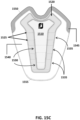
- the article of footwear may be configured to receive or accommodate one or more replaceable or interchangeable arch supports 600, e.g., as shown in FIGURE 7 .
- the interchangeable arch supports 600 may be configured to accommodate a transverse and/or longitudinal arch shape or profile of a subject's foot.
- the interchangeable arch supports 600 may have different arch heights to accommodate variations in arch height across different subjects.
- the one or more replaceable or interchangeable arch supports 600 may be detachably coupled to the medial support 520. In some cases, the one or more replaceable or interchangeable arch supports 600 may be fastened to an elongated section 525 of the medial support 520. In some cases, the one or more replaceable or interchangeable arch supports 600 may be attached or coupled to a fastener 535 provided on the medial support. In some cases, the one or more replaceable or interchangeable arch supports 600 may be attached or coupled to a necked or tapered portion 515 of the elongated section 525 of the medial support 520. In some cases, the one or more replaceable or interchangeable arch supports 600 may be attached or coupled to a portion of the elongated section 525 that is located between the plurality of stretchable sections 530 of the medial support 520.
- the medial support 520 may comprise a first end 521 and a second end 522.
- the first end 521 may comprise a fastener for coupling the medial support 520 to the insole component of the article of footwear.
- the fastener may comprise a hook or loop fastener.
- the fastener may be configured to couple the first end 521 of the medial support 520 to a connecting strap 701 that is attached to the insole component.
- the connecting strap 701 may be attached to an underside or bottom of the insole component. In other cases, the connecting strap 701 may be attached to a top surface of the insole component.
- the connecting strap 701 may be attached to a medial side of the insole component. In other cases, the connecting strap 701 may be attached to a lateral side of the insole component. In some embodiments, the connecting strap 701 may include a corresponding hook or loop fastener configured to engage with the fastener provided on the first end 521 of the medial support 520.
- the second end 522 of the medial support 520 may comprise one or more extensions that are foldable to form an enclosed loop that can engage a lace or a cable.
- each of the one or more extensions may be folded onto itself, and the folded ends may be secured using one or more fasteners 536 disposed on the extensions.
- the folded ends may comprise one or more corresponding fasteners 536 for securing the folded ends to the fasteners 536 disposed on the extensions.
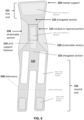
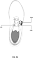
- the support system may comprise a lateral support 950.
- the lateral support 950 may comprise a support structure configured to extend along at least a portion of the lateral side of the article of footwear.
- the lateral support 950 may comprise a curved plate.
- the lateral support 950 may comprise a carbon fiber plate.
- the lateral support 950 may have a greater hardness, stiffness, or tensile strength than the upper of the article of footwear.
- the lateral support 950 may have a greater hardness, stiffness, or tensile strength than the sole assembly of the article of footwear.
- a portion of the lateral support 950 may be configured to extend under or along the insole component of the article of footwear. In some cases, a portion of the lateral support 950 may be configured to extend between the medial side and the lateral side of the article of footwear. In some cases, a portion of the lateral support 950 may be configured to extend to or from a lateral side bite line formed between the upper and the sole assembly. In some cases, a first portion of the lateral support 950 may be configured to extend under a subject's foot between the lateral side bite line and a medial side of the article of footwear. In some cases, a second portion of the lateral support 950 may be configured to extend around or over a lateral side of the subject's foot.
- the second portion of the lateral support 950 may be configured to extend over an inner surface of the upper. In some cases, the second portion of the lateral support 950 may be configured to extend over an outer or outward facing surface of the upper. The outer or outward facing surface of the upper may correspond to a surface of the upper that is directly exposed to an external environment surrounding the article of footwear.
- a portion of the lateral support 950 may be coupled to an upper surface or a bottom surface of a sole component of the article of footwear.
- the sole component may include a midsole and/or an insole component of the article of footwear.
- a portion of the lateral support 950 may be coupled to an upper surface of the midsole.
- a portion of the lateral support 950 may be coupled to a bottom surface of the insole component.
- the lateral support 950 may be coupled to the medial side of the insole component or the midsole.
- the lateral support 950 may be coupled to the lateral side of the insole component or the midsole.
- the lateral support 950 may be coupled to a portion of the insole component or midsole that is located between the medial and lateral sides of the insole component or midsole.
- the lateral support 950 may be detached or decoupled from the upper and free floating and/or independently movable relative to the upper. In some cases, the lateral support 950 may be configured to wrap over or translate along, over, or across the upper in response to a level of tension in a securement system for the article of footwear. In some cases, the lateral support 950 may be configured to rotate about a bite line of the shoe (e.g., towards the lateral side of the upper and/or away from the lateral side of the upper).
- the lateral support 950 may be positioned within a pocket or a sleeve 960 that is integrated with the upper. In some cases, the pocket or sleeve 960 may be positioned over or above an inner surface of the upper. In some cases, the pocket or sleeve 960 may be positioned on or within an outer surface of the upper. In some cases, the lateral support 950 may be sleeved into the upper to minimize bulk and improve aesthetics. In some cases, the body or surface of the lateral support 950 may not or need not be attached to the upper. In some cases, the lateral support 950 may be free floating and configured to move within the pocket or sleeve 960 relative to the lateral side of the upper.
- the lateral support 950 may be sleeved into the upper in a visible configuration.
- the sleeve 960 may comprise a window 970 for exposing or revealing the lateral support 950 positioned within the sleeve 960.
- the window may be a cut out, or may comprise a transparent material.
- the lateral support 950 may be sleeved into the upper in a non-visible configuration.
- the sleeve 960 may not or need not comprise any windows, openings, or transparent materials that expose or reveal the sleeved lateral support.
- the lateral support 950 may comprise a slot 951 configured to receive a webbing 952 for connecting the lateral support 950 to a securement system or a cable 1010 of the securement system (e.g., as described in further detail below).
- the slot 951 may be disposed on an end of the lateral strap that is positioned along a lateral side of a subject's foot.
- a portion of the webbing 952 may be configured to extend through an interior region or volume of the upper.
- a portion of the webbing 952 may extend through the sleeve and out towards the throat of the shoe in order to engage a cable 1010 of the securement system.
- the article of footwear may comprise a securement system extending between the medial and lateral sides of the article of footwear.
- the securement system may be configured to tighten the support system around a subject's foot while securing the subject's foot down and back towards the heel region of the article of footwear.
- the securement system may be optimized to provide a more direct linkage between the medial and lateral supports of the support system, thereby allowing the medial and lateral supports to be drawn more tightly together in tension, and further enhancing lateral rigidity.
- the securement system may be configured to operate with minimal frictional losses.
- the securement system may comprise one or more cables.
- the one or more cables may comprise two or more cables that are independently adjustable.
- the two or more cables may not or need not be directly connected. In some cases, changing the amount of tension in one of the two or more cables may not or need not change the amount of tension in the other cables of the securement system.
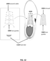
- FIGURES 11 and 12 schematically illustrate a securement system for securing the subject's foot.
- the securement system may comprise a first securement system comprising a first cable 1010.
- the securement system may comprise a second securement system comprising a second cable 1020.
- the securement system may comprise a first cable 1010 configured to (a) pull the insole component up against a plantar surface of the foot and (b) draw the foot towards a lateral side of the article of footwear.
- the first cable 1010 may be configured to secure the medial and lateral supports around a subject's foot to provide a 360 degree fit.
- the first cable 1010 may be configured to engage with the lateral support 950 via a webbing 952 that is inserted or threaded through a slot provided in the lateral support 950.
- the first cable 1010 may also engage the looped second ends 522 of the medial support. The looped second ends 522 of the medial support may be positioned or located across from the webbing 952 that extends from the lateral support 950.
- the first cable 1010 may be configured to engage additional webbing 1222 provided on a same side as the looped second ends 522 of the medial support or the webbing 952 extending from the lateral support 950. In other cases, the first cable 1010 may be configured to engage additional webbing 1222 provided on a different side than the looped second ends 522 of the medial support or the webbing 952 extending from the lateral support 950.
- the looped second ends 522 of the medial support, the webbing 952 extending from the lateral support 950, and the additional webbing 1222 may be configured to route the first cable 1010 across the tongue or the upper of the shoe.
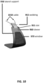
- a side mounted dial 1110 may be used to activate the first cable 1010 (e.g., to increase or decrease tension in the first cable 1010 and draw the internal medial and lateral supports together and/or away from each other).
- the securement system may comprise a second cable 1020 configured to (a) adjustably secure the upper around the foot and (b) pull a subject's foot down and back towards a heel region of the article of footwear.
- the second cable 1020 may be configured as or may comprise throat lacing for the article of footwear. In some cases, the throat lacing may extend across the top of the upper and/or across the tongue of the article of footwear.
- a heel mounted dial 1120 may be used to activate the second cable 1020 (e.g., to tighten the lacing across the throat and/or to draw a subject's foot down and back towards the heel region of the article of footwear).
- the article of footwear may comprise a shroud 1050 that is configured to separate the first cable 1010 and the second cable 1020.
- the shroud 1050 may comprise a panel or layer of material.
- the shroud 1050 may be positioned between the first cable 1010 and the second cable 1020 to minimize interference between the first cable 1010 and the second cable 1020 (e.g., when operating the securement system or when adjusting the midfoot support system around a subject's foot).
- the first cable 1010 may be located above the shroud 1050 and/or the second cable 1020.
- the second cable 1020 may be located above the shroud 1050 and/or the first cable 1010.
- the shroud 1050 may comprise one or more lace guides 1060.
- the one or more lace guides 1060 may be configured to receive one or more segments of the second cable 1020 and to guide or direct the one or more segments to one or more eyelets disposed along the upper.
- the one or more lace guides 1060 may be configured to extend along a longitudinal length of the shroud 1050.
- the article of footwear may comprise one or more dials configured to adjust or control the one or more cables of the securement system.
- the one or more dials may comprise a side mounted dial 1110 configured to adjust or control the first cable 1010 and/or the second cable 1020 of the securement system.
- the one or more dials may comprise a heel dial 1120 configured to adjust or control the first cable 1010 and/or the second cable 1020 of the securement system.
- the side mounted dial 1110 may be configured to adjust or control the first cable 1010. In some cases, the side mounted dial 1110 may be used to accommodate the shape or profile of a subject's transverse arch. In some cases, the side mounted dial 1110 may be used to accommodate variations in arch height.
- the heel mounted dial 1120 may be configured to adjust or control the second cable 1020. In some cases, the heel mounted dial 1120 may be configured to position or move a subject's foot down and back towards the heel region of the article of footwear, as described in further detail above.
- the golf shoe may comprise a cable management system.
- the cable management system may be configured to reduce or prevent interaction or interference between two or more cable systems.
- the cable management system may enhance the aesthetic appearance of the shoe by hiding portions or segments of the two or more cable systems to avoid a cluttered and busy visual presentation.
- the cable management system may include one or more cable or lace guides.
- one or more portions or segments of the cable systems may be routed through the one or more cable or lace guides.
- the one or more cable or lace guides may be configured to control or manage a position, an orientation, and/or a movement of the one or more portions or segments of the cable systems.
- the one or more cable or lace guides may comprise a guide with a housing and one or more enclosed or partially enclosed channels extending through the housing.
- the guide may comprise a plurality of channels configured to control or manage a position, an orientation, and/or a movement of one or more laces or cables extending across the throat of the shoe (e.g., as the laces or cables are loosened and/or tightened).
- the one or more cable or lace guides may comprise a webbing or a shroud that extends over and conceals one or more cables used to control the lateral and/or medial stability flaps of the shoe.
- the webbing or shroud may be removable.
- the webbing or shroud may be integrally formed with or detachably fixed to another portion of the shoe.
- the cable management system may comprise a layered tongue that extends over and conceals one or more cables used to control the lateral and/or medial stability flaps of the shoe.
- the layered tongue may comprise two or more layers with one or more cable or lace guides formed between the layers of the layered tongue.
- the cables or laces of the shoe may extend through the cable or lace guides formed between the layers of the layered tongue.
- the layered tongue may comprise three or more layers. In some cases, the three or more layers may provide multiple sets of cable or lace guides for different cables or different sets of cables. In some cases, the layered tongue may comprise a layer that separates (i) the cables for controlling the throat lacing and (ii) the cables for controlling the lateral and/or medial stability flaps of the shoe.
- the cable management system may comprise a sheathed tongue assembly that extends over and conceals one or more cables used to control the lateral and/or medial stability flaps of the shoe.
- the sheathed tongue assembly may comprise one or more sheaths attached to the tongue of the shoe.
- the sheathed tongue assembly may comprise a tongue assembly with one or more layers configured as a sheath for the laces or cables of the shoe.
- the sheathed tongue assembly may comprise a tongue assembly with at least one layer separating (i) the cables for controlling the throat lacing and (ii) the cables for controlling the lateral and/or medial stability flaps of the shoe.
- the sheathed tongue assembly may comprise a relatively firm and smooth material on which the laces or cables can easily slide, such as a thermoplastic polyurethane (TPU) or a nylon material.
- a portion of the tongue assembly may comprise an inner liner or lining material for added comfort or enhanced moisture or climate control.
- the sheathed tongue assembly may be structured to resist deforming or contorting under lace pressure while also conforming or adapting to the shape of a subject's foot when the laces or cables of the shoe are tightened.
- the sheathed tongue assembly may be used in combination with other cable or lace guides as described elsewhere herein. In other cases, the sheathed tongue assembly may be used exclusively, without any other cable or lace guides.
- a flat panel or extended surface can be attached to or integrated with a portion or a surface of a cable or lace guide facing the underlying tongue.
- the flat panel or extended surface may be configured as a sheath.
- the cable or lace guide and the sheath may form a unitary construction that can (i) guide a first cable or a first set of cables through the cable or lace guide portion while (ii) covering or concealing a second cable or a second set of cables and (iii) separating the first and second cables or sets of cables using the sheath portion.
- an integrated sheath and cable or lace guide assembly can be used to guide an outer cable across the throat region of the shoe.
- the integrated sheath and cable or lace guide assembly may hide or cover an inner cable with a different fit-related function than the outer cable.
- the integrated sheath and cable or lace guide assembly may be configured to physically separate the outer cable and the inner cable to avoid interactions or interference between the inner cable and the outer cable.
- one or more separate panels or sheaths can be attached to the tongue of the shoe to form one or more lace or cable guides.
- an inner cable and/or an outer cable may be configured to extend under or between the panels and/or the tongue of the shoe.
- an inner cable and/or an outer cable may be configured to extend through one or more lace or cable guides as described elsewhere herein.
- FIGURES 13A - 13B schematically illustrate one more cables 1320 that can be used to secure a shoe around a subject's foot.
- the one more cables 1320 may be arranged in a lacing pattern across a portion of the shoe.
- the lacing pattern may be formed using one or more cable guides 1305.
- the one or more cable guides 1305 may comprise one or more lugs, loops, or hooks.
- the lacing pattern may be formed using one or more eyelets or openings disposed in or near an eye stay region of the upper.
- one or more tube guides 1310 may be included.
- the cables 1320 of the cable systems may be routed through a tube guide 1310 extending laterally across or along the throat of the shoe.
- the tube guide 1310 may pinch the cables 1320 at or near the ends of the tube guides 1310 to manage a position, an orientation, or a movement of one or more cables 1320 routed through the tube guide 1310.
- the cables 1320 may be tensioned when the cable systems are activated (e.g., to tighten the upper around the subject's foot, to lock the subject's foot within the shoe, or to bias the subject's foot towards a target region in the shoe).
- the tension (T 1,2 ) in the cables 1320 may comprise an X-component (T X ) and/or a Y-component (T Y ).
- the X-component (T X ) may be aligned along a length or a width of the tube guide 1310.
- the Y-component (T Y ) may be aligned along a direction that is perpendicular to the length or the width of the tube guide 1310.
- the X-component (Tx) acts along the length or width of the tube guide 1310, there is minimal friction (or no friction) between the inner surfaces of the tube guide 1310 and the portions of the cables 1320 that extend through the tube guide 1310. There is also no stress (or minimal stress) on the length or width of the tube guides 1310 due to the X-component (Tx).
- the Y-component may cause the cables 1320 to move in opposite directions (e.g., perpendicular to the length or width of the tube guides 1310) so that the cables 1320 act to spread apart the ends of the tube guides 1310 when placed in tension.
- the points of contact between the cables 1320 and the ends of the tube guide 1310 may create friction and interfere with the functionality of the cable systems.
- the points of contact may change or influence how the tightening or loosening of the cable systems affects (i) the actual or perceived fit of different portions of the shoe around a subject's foot and/or (ii) the positional locking or bias of the subject's foot within the shoe.
- the shoes of the present disclosure may utilize one or more multi-directional cable guides 1350 to prevent or minimize points of contact between the cable systems and the cable guides 1350.
- the multi-directional cable guides 1350 may comprise a plurality of channels configured to receive and direct various cable segments across the throat region of the shoe.
- the multi-directional cable guides 1350 may comprise a butterfly guide.
- the butterfly guide may have a housing with two or more diagonal channels extending through the housing.
- the two or more diagonal channels may be arranged in an X-shaped configuration.
- the one or more cables 1320 of the cable systems may be configured to extend through the diagonal channels of the butterfly guide.
- the diagonal channels may be oriented along a direction in which the cables 1320 are positioned, oriented, or configured to move, in order to minimize friction between the surfaces of the butterfly guide and the cables 1320 of the cable system.
- the multi-directional cable guides may comprise a low friction material.
- the low friction material may comprise, for example, a plastic material or a thermoplastic material.
- the multi-directional cable guides may comprise a three-dimensional (3D) printed component.
- the 3D printed component may comprise a plastic material or a thermoplastic material.
- the 3D printed component may comprise a composite material.
- the shoes of the present disclosure may alternatively or additionally utilize a sheath construction 1360.
- the sheath construction 1360 may comprise a flat or substantially flat panel or layer of material.
- one or more portions of the sheath construction 1360 may be fixed or coupled to another portion or component of the shoe at one or more attachment points.
- one or more other portions of the sheath construction 1360 may be detached from the rest of the shoe.
- the sheath construction 1360 may be configured to organize or manage a position or a spatial arrangement of one or more cables 1320 of the cable systems (e.g., by controlling or limiting the range of movement of the cables 1320 when the cable systems are loosened or tightened). In some cases, the sheath construction 1360 may constrain the cables 1320 so that the cables generally stay within a select boundary region defined by the one or more attachment points (or a subset thereof).
- the sheath construction 1360 may comprise a low friction material. In some cases, the sheath construction 1360 may comprise a low-stretch or non-stretch material. In some non-limiting embodiments, the sheath construction 1360 may comprise a plastic material.
- FIGURES 14A and 14B illustrate additional examples of cable management systems.
- the cable management systems may include or utilize one or more cable guides 1400.
- the one or more cable guides 1400 may comprise one or more multi-directional cable guides.
- the multi-directional cable guides may include at least one or more X-shaped cable guides as described elsewhere herein.
- the cable management system may include a webbing overlay 1401 (e.g., as shown in FIGURE 14A ).
- the webbing overlay 1401 may be configured to act as a lace or cable guide and control or manage a position, an orientation, or a movement of one or more cables extending across the throat region of the shoe.
- the webbing overlay 1401 may conceal one or more portions or segments of the one or more cables.
- the one or more cables may include (i) cables for throat lacing and/or (ii) cables for activating or deactivating the lateral support strap and/or the medial support strap of the shoe.
- the cable management systems may include a tongue with two or more layers.
- the two or more layers may form a tongue overlay construction 1402 that can be configured to act as a lace or cable guide and control a position, an orientation, or a movement of one or more cables extending across the throat region of the shoe.
- the tongue overlay construction 1402 may cover or conceal one or more cables extending across the shoe.
- the one or more cables may include (i) cables for throat lacing and/or (ii) cables for activating or deactivating the lateral support strap and/or the medial support strap of the shoe.
- the cable management system may comprise a multi-layer construction.
- the multi-layer construction may include a first layer 1510 that is attached to a second layer 1520.
- the first layer 1510 and/or the second layer 1520 may comprise a synthetic material (e.g., polyurethane).
- first and second layers 1510, 1520 may be stitched together at one or more attachment points 1515.
- one or more portions or sections of the first and second layers 1510, 1520 may be detached from each other to create one or more partially enclosed or covered regions between the first and second layers.
- the partially enclosed or covered regions may extend across a length or a width of the first and/or second layer.
- the one or more partially enclosed or covered regions may be configured as one or more guides 1530.
- one or more laces or cables of the shoe may be configured to extend through the partially enclosed or covered regions forming the guides 1530.
- the one or more laces or cables of the shoe may be configured to extend along a path that extends through the partially enclosed or covered regions forming the guides 1530.
- the guides 1530 formed between the first layer 1510 and the second layer 1520 may be configured to organize or manage a position, an orientation, and/or a movement of one or more laces or cables used to (i) tighten or loosen the throat region of the shoe or (ii) engage or disengage the lateral support strap and/or the medial support strap of the shoe.
- the second layer 1520 may be attached to the top cover of the tongue (also referred to herein as the tongue top cover 1540). In some cases, the second layer 1520 and the top cover of the tongue may be stitched together at one or more attachment points 1525. In some cases, one or more portions or sections of the second layer 1520 and the top cover of the tongue may be detached from each other to create one or more partially enclosed or covered regions between the second layer 1520 and the top cover of the tongue. In some cases, the partially enclosed or covered regions may extend across a length or a width of the second layer 1520 or the top cover of the tongue. In some cases, the one or more partially enclosed or covered regions may be configured as one or more guides 1535.
- one or more laces or cables of the shoe may be configured to extend through the partially enclosed or covered regions forming the guides 1535. In some cases, the one or more laces or cables of the shoe may be configured to extend along a path that extends through the partially enclosed or covered regions forming the guides 1535. In some cases, the guides 1535 formed between the second layer 1520 and the top cover of the tongue may be configured to organize or manage a position, an orientation, and/or a movement of the cables or laces used to (i) tighten or loosen the throat region of the shoe or (ii) engage or disengage the lateral support strap and/or the medial support strap of the shoe.
- a set of stitches may be used to attach the first layer 1510 and the second layer 1520 to the tongue top cover and/or the tongue liner.
- the set of stitches may be configured to attach the first and second layers together and/or to other portions of the tongue assembly as needed to form the one or more cable or lace guides described herein.
- a single row stitch may be used to attach the second layer 1520 to the bottom portion of the tongue top cover and/or the tongue liner (e.g., to provide sufficient clearance for the cables extending through the guides at or near the bottom of the tongue).
- the tongue top cover 1540 may be assembled with a tongue liner 1545.
- the tongue liner 1545 may extend past an upper edge of the tongue top cover.
- the tongue top cover 1540 may be attached to the tongue liner 1545 at one or more attachment points 1550.
- the first layer 1510, the second layer 1520, the tongue top cover 1540, and the tongue liner 1545 may form a tongue assembly.
- the tongue assembly comprising the first layer 1510, the second layer 1520, the tongue top cover 1540, and the tongue liner 1545 may be attached or coupled to the rest of the shoe.
- a bottom or lower portion of the tongue assembly may be stitched to a portion of the upper (e.g., at one or more attachment points 1555).
- a first cable 1571 and a second cable 1572 may be used to secure the subject's foot.
- the first cable 1571 may correspond to a cable system connected to a heel dial of the shoe in order to control the throat lacing.
- the second cable 1572 may correspond to a cable system connected to a side mounted dial in order to control the lateral support (also referred to herein as a lateral stability flap) and/or the medial support (also referred to herein as a medial strap) of the shoe.
- the first cable 1571 may be configured to extend across or over a portion of the first layer 1510 and/or the second layer 1520 of the multi-layer construction. In some cases, the first cable 1571 may be configured to extend across or over a portion of the tongue top cover 1540 and/or the tongue liner 1545.
- the first cable 1571 may extend through one or more openings provided along the upper of the shoe. In some cases, the first cable 1571 may extend through one or more tubular guides or looped structures configured to control a position, an orientation, and/or a movement of one or more segments of the first cable 1571.
- the first cable 1571 may extend through one or more guides formed between the first layer 1510 and the second layer 1520 of the multi-layer construction. In some cases, the first cable 1571 may cross over itself as it extends through the guides formed between the first layer 1510 and the second layer 1520. As described above, the guides may correspond to portions or sections of the first and second layers 1510, 1520 that are detached from each other to form one or more partially enclosed or covered regions that extend between the first and second layers. In some cases, the partially enclosed or covered regions may be bounded by one or more attachment points coupling the first layer 1510 and the second layer 1520 together. In some cases, the one or more partially enclosed or covered regions formed between the first and second layers 1510, 1520 may be configured as the one or more guides for the first cable 1571.
- the second cable 1572 may be configured to extend across or over a portion of the tongue top cover 1540. In some cases, the second cable 1572 may be configured to extend under the first layer 1510 and/or the second layer 1520. In some cases, the second cable 1572 may be configured to extend through one or more tubular guides or looped structures. In some cases, the looped structures may correspond to the looped ends of the second end 522 of the medial support 520 (e.g., as shown in FIGURES 7 and 8A - 8C ). In some cases, the looped structures may include one or more looped structures formed by a webbing material extending from the lateral stability flap (e.g., as shown in FIGURES 10 and 11 ). In some cases, the looped structures may include one or more looped structures formed by additional webbing material provided along the throat region of the shoe (e.g., as shown in FIGURE 11 ).
- the second cable 1572 may extend through one or more guides formed between the second layer 1520 of the multi-layer construction and the tongue top cover 1540. In some cases, two or more segments of the second cable 1572 may cross as they extend through the guides formed between the second layer 1520 and the tongue top cover 1540. As described above, the guides may correspond to portions or sections of the second layer 1520 and the tongue top cover 1540 that are detached from each other to form one or more partially enclosed or covered regions that extend between the second layer 1520 and the tongue top cover 1540. In some cases, the partially enclosed or covered regions may be bounded by one or more attachment points coupling the second layer 1520 and the tongue top cover 1540 together. In some cases, the one or more partially enclosed or covered regions formed between the second layer 1520 and the tongue top cover 1540 may be configured as the one or more guides for the second cable 1572.
- FIGURE 16 illustrates a toe down view of an exemplary golf shoe 1600 of the present disclosure.
- the golf shoe 1600 may comprise a cable management system 1610 as described elsewhere herein.
- the cable management system 1610 may be configured to manage or organize a plurality of cables to minimize interactions or interferences between the plurality of cables.
- the cable management system 1610 may be configured to cover or conceal at least a portion of the plurality of cables to provide a more pleasing and attractive aesthetic look.
- the plurality of cables may include a first cable 1620 that can be tightened or loosened using a first dial 1621.
- the plurality of cables may include a second cable 1630 that can be tightened or loosened using a second dial 1631.
- the tightening or loosening of the first cable 1620 may engage or disengage the throat lacing.
- the tightening or loosening of the second cable 1630 may engage or disengage a lateral support 1650 and/or a medial support 1660 of the shoe.
- the lateral support 1650 may be detached from the upper and/or sleeved within a portion of the upper, and may extend around a lateral side of a subject's foot.
- the medial support 1660 may extend under and around a medial side of a subject's foot to cradle the medial side of the subject's foot. As described elsewhere herein, the lateral support 1650 and the medial support 1660 may be indirectly coupled via one or more cables extending between the lateral support 1650 and the medial support 1660, and drawn together under tension (e.g., by using one or more tightening mechanisms operatively coupled to the one or more cables) to secure the subject's foot within the shoe.
- the second dial 1631 may be attached or coupled to the lateral support 950. In some embodiments, the second dial 1631 may be attached or coupled to a layer or a panel of the shoe that is directly or indirectly attached to the lateral support 950.
- the second dial 1631 may extend through a portion of the lateral support 950.
- the lateral support 950 may comprise an opening, an aperture, or a channel configured to receive the second dial 1631.
- the second dial 1631 may be configured to extend through the opening, aperture, or channel of the lateral support 950.
- the second dial 1631 may have a fixed spatial relationship relative to the lateral support 950. In some cases, the second dial 1631 and the lateral support 950 may move synchronously along or across the upper when the second dial 1631 is operated to engage the lateral support 950 and/or the medial support.
- the second dial 1631 and the lateral support 950 may not or need not maintain a fixed spatial relationship.
- the second dial 1631 may be stationary and the lateral support 950 may be configured to move along or across the upper when the second dial 1631 is operated to engage or disengage the lateral support 950 and/or the medial support.
- the relative spatial relationship between the lateral support 950 and the second dial 1631 may change or vary as the second dial 1631 is operated to engage or disengage the lateral support and/or the medial support.
- the golf shoe 1700 may comprise a support.
- the support may comprise a medial support and/or a lateral support.
- the support may comprise a support structure.
- the support structure may comprise a molded support structure, a composite support structure, or a molded composite support structure.
- the support structure may comprise a plate (e.g., a support plate, a molded plate, a composite plate, a carbon plate, etc.).
- the support structure may comprise a support strap, a support flap, a stability strap, a stability flap, or any other support structure that can (i) manage a load during a golf-related action or movement and/or (ii) control a positioning and/or a movement of a subject's foot during a golf-related action or movement.
- the support structure may comprise a composite material.
- the composite material may comprise one or more fibers (e.g., one or more composite fibers or one or more carbon fibers).
- the composite material may comprise one or more thermoset materials and/or one or more thermoplastic materials.
- the support structure may comprise a polymer-based composite material.
- the polymer-based composite material may comprise a polymeric matrix comprising one or more reinforcing fibers.
- the polymer-based composite material may comprise, for example, a polypropylene matrix reinforced with one or more polypropylene fibers.
- the support structure may include a lateral support structure.
- the lateral support structure may be configured as a lateral support against which a subject's foot can be positioned for increased stability and/or control during a golf-related action or movement.
- the golf shoe 1700 may further comprise a medial support structure.
- the medial support structure may be configured as a medial support against which a subject's foot can be positioned for increased stability and/or control during a golf-related action or movement.
- the lateral and medial support structures may be secured around a subject's foot using a cable system.
- the cable system, the lateral support structure, and the medial support structure may be configured to operate as an internal 360 degree support system or a 360 degree internal support system for the shoes described herein.
- the shoe may comprise a lateral support 1710.
- the lateral support1710 may comprise a first end, a second end, and a body extending between the first end and the second end.
- the body of the lateral support 1710 may be configured to extend along a lateral side of the subject's foot.
- the lateral support may comprise, for example, a support plate, a support strap, a stability flap, or any of the other support structures described elsewhere herein.
- a portion of the lateral support 1710 may be configured to extend under an insole component of the shoe. In some cases, the lateral support 1710 may not or need not extend under the insole component of the shoe. In some cases, the lateral support 1710 may be positioned entirely above the insole component of the shoe.
- a first end of the lateral support 1710 may be affixed to a lateral side of the shoe. In other cases, the first end of the lateral support 1710 may be affixed to a medial side of the shoe. In some alternative cases, the first end of the lateral support 1710 may be affixed to a portion of the shoe that is located between the medial and lateral sides of the shoe.
- the first end of the lateral support 1710 may be affixed to a portion or a component of the shoe.
- the portion or component may be disposed adjacent or proximal to the bite line of the shoe.
- the bite line may correspond to a region of the shoe along which the upper and the sole assembly meet, intersect, or converge.
- the bite line may extend along at least a lateral side and/or a medial side of the shoe.
- the body of the lateral support 1710 may extend from the first end towards a second end disposed along an upper portion of the shoe.
- a cable adjustment mechanism 1720 for activating or deactivating one or more cable systems of the shoe may be disposed or mounted on the second end of the lateral support 1710.
- the one or more cable systems may include a cable system for controlling the 360 degree internal support systems described herein.
- the cable adjustment mechanism 1720 may include, for example, a dial and a spool assembly for organizing a cable system for the shoe.
- the cable adjustment mechanism 1720 may be operated to adjust a tension in the cable system to tighten the lateral support and/or the medial support of the shoe around a subject's foot. In some cases, the cable adjustment mechanism 1720 may be operated to adjust the tension in the cable system in order to release the lateral and/or medial supports from around the subject's foot.
- a separate heel mounted cable adjustment mechanism 1730 may be provided to control another cable system for the shoe.
- the heel mounted cable adjustment mechanism 1730 may be operated independently of the cable adjustment mechanism 1720 mounted on the second end of the lateral support 1710.
- the heel mounted cable adjustment mechanism 1730 may be used to control the throat lacing for the shoe without affecting the tension in the cable system for the 360 degree internal support system.
- the lateral support 1710 may comprise a flat or substantially flat section or segment that extends through a slit provided along an upper portion of the shoe.
- the flat or substantially flat section or segment may be detached and free floating along the upper portion of the shoe.
- the section or segment of the plate extending through the slit may be configured to wrap around or over the lateral side of the upper portion of the shoe when the cable adjustment mechanism 1720 is operated to tighten the cable system for the internal 360 degree support system.
- the flat or substantially flat section or segment may comprise an end portion with an opening for receiving a dial component of the cable adjustment mechanism.
- the dial component may be configured to extend through the opening and interface with a receptacle component positioned on the other side of the opening across from the dial component.
- the dial component and the receptacle component may be assembled together to form a cable adjustment mechanism that can be operated to activate or deactivate the internal 360 degree support system.
- the lateral support 1810 may comprise a curved section or segment.
- the curved section or segment may comprise a first end that extends into the shoe (e.g., in between the liner and the outer shell of the shoe) and/or underneath an insole component of the shoe.
- the curved section or segment may comprise a second end with an opening 1830 for receiving a dial component 1820.
- the dial component 1820 may be configured to extend through the opening 1830 and interface with a receptacle component 1825 positioned on the other side of the opening 1830 across from the dial component 1820.
- the dial component 1820 and the receptacle component 1825 may be assembled together to form a cable adjustment mechanism that can be operated to activate or deactivate the internal 360 degree support system of the shoe.
- a portion of the curved section or segment of the lateral support 1810 may extend through a slit 1815 provided along an upper portion of the shoe.
- the curved section or segment may be detached and free floating along the upper portion of the shoe.
- the curved section or segment extending through the slit may be configured to wrap around or over the lateral side of the upper portion of the shoe when the cable adjustment mechanism 1720 is operated to tighten the cable system for the internal 360 degree support system.
- the lateral support 1810 may be reinforced using a curved reinforcement layer 1850.
- the curved reinforcement layer 1850 may be configured to stiffen the base of the lateral support 1810.
- the curved reinforcement layer 1850 may be configured to stiffen the curved section or segment of the lateral support 1810.
- the curved reinforcement layer 1850 may comprise a composite material or a laminate layer that is integrated with the lateral support 1810 before or after the lateral support 1810 is fully formed (e.g., molded, printed, etc.).
- the curved reinforcement layer 1850 may have a curved shape or profile corresponding to a curvature of the curved section or segment of the lateral support 1810.
- the shoe 1700 may comprise one or more cable guides for organizing one or more cable systems of the shoe.
- the one or more cable guides may include one or more floating guides 1741 extending from the upper towards the throat region of the shoe.
- the one or more cable guides may optionally or alternatively include one or more X-shaped cable guides 1742 as described elsewhere herein.
- the shoe may comprise one or more cable guides 2010 comprising a multi-layer textile piece.
- the multi-layer textile piece may comprise a top portion, a bottom portion, and a folded edge 2011 extending between the top and bottom portions.
- the multi-layer textile piece may comprise one or more side openings configured to receive one or more cables or cable segments.
- the cable guides 2010 may comprise two ends opposite the folded edge 2011.
- the two ends may include (i) an end of the top portion of the multi-layer textile piece and (ii) an end of the bottom portion of the multi-layer textile piece.
- the two ends opposite the folded edge 2011 may be attached or affixed to one another to form a partially enclosed interior region extending between the top and bottom portions of the multi-layer textile piece.
- the partially enclosed interior region may be configured to control or guide a positioning and/or a movement of one or more cables or cable segments of the cable system (e.g., as a subject operates a cable adjustment mechanism to engage or disengage the cable system).
- the multi-layer textile piece may comprise a synthetic material.
- the synthetic material may comprise, for example, a polyurethane-based material.
- the synthetic material may comprise a nylon-based or a polyester-based material.
- the multi-layer textile piece may include a natural material (e.g., cotton, linen, silk, wool, etc.).
- FIGURE 21 illustrates an example of a shoe with a cable adjustment mechanism 2120 that is mounted to a support structure of the lateral support of the shoe.
- the cable adjustment mechanism 2120 may be configured to control an amount of tension in a cable system extending between the medial support and the lateral support of the shoe.
- the cable system may extend through (i) the looped ends of the second end 522 of the medial support of the shoe and (ii) a housing of the cable adjustment mechanism 2120 mounted to the lateral support, to indirectly couple the lateral and medial supports to each other.
- the cable adjustment mechanism 2120 may tension the cable system to draw the lateral and medial supports of the shoe around the subject's foot in order to lock the subject's foot in a desired position and/or orientation.
- one or more cable guides 2130 may be used to control or guide a positioning and/or a movement of the one or more cables or cable segments of the cable system.
- the one or more cable guides 2130 may include one or more internal cable guides.
- the one or more cable guides 2130 may include a webbing that is affixed to an upper portion of the shoe. In some cases, the webbing may be affixed along an eye stay region or a throat region of the shoe. In some cases, the webbing may be affixed to a liner component for the throat or collar region of the shoe.
Landscapes
- Health & Medical Sciences (AREA)
- General Health & Medical Sciences (AREA)
- Epidemiology (AREA)
- Public Health (AREA)
- Physical Education & Sports Medicine (AREA)
- Footwear And Its Accessory, Manufacturing Method And Apparatuses (AREA)
Priority Applications (1)
| Application Number | Priority Date | Filing Date | Title |
|---|---|---|---|
| EP25197935.7A EP4627962A3 (fr) | 2023-07-27 | 2024-06-13 | Système de support de pied milieu de chaussure |
Applications Claiming Priority (1)
| Application Number | Priority Date | Filing Date | Title |
|---|---|---|---|
| US18/226,897 US20240197031A1 (en) | 2022-12-15 | 2023-07-27 | Footwear midfoot support system |
Related Child Applications (2)
| Application Number | Title | Priority Date | Filing Date |
|---|---|---|---|
| EP25197935.7A Division EP4627962A3 (fr) | 2023-07-27 | 2024-06-13 | Système de support de pied milieu de chaussure |
| EP25197935.7A Division-Into EP4627962A3 (fr) | 2023-07-27 | 2024-06-13 | Système de support de pied milieu de chaussure |
Publications (3)
| Publication Number | Publication Date |
|---|---|
| EP4497344A1 true EP4497344A1 (fr) | 2025-01-29 |
| EP4497344C0 EP4497344C0 (fr) | 2025-10-29 |
| EP4497344B1 EP4497344B1 (fr) | 2025-10-29 |
Family
ID=91580828
Family Applications (2)
| Application Number | Title | Priority Date | Filing Date |
|---|---|---|---|
| EP24182125.5A Active EP4497344B1 (fr) | 2023-07-27 | 2024-06-13 | Système de support de médio-pied de chaussure |
| EP25197935.7A Pending EP4627962A3 (fr) | 2023-07-27 | 2024-06-13 | Système de support de pied milieu de chaussure |
Family Applications After (1)
| Application Number | Title | Priority Date | Filing Date |
|---|---|---|---|
| EP25197935.7A Pending EP4627962A3 (fr) | 2023-07-27 | 2024-06-13 | Système de support de pied milieu de chaussure |
Country Status (3)
| Country | Link |
|---|---|
| EP (2) | EP4497344B1 (fr) |
| JP (1) | JP2025018944A (fr) |
| KR (2) | KR102885263B1 (fr) |
Families Citing this family (1)
| Publication number | Priority date | Publication date | Assignee | Title |
|---|---|---|---|---|
| KR102930409B1 (ko) | 2025-12-05 | 2026-02-26 | (주)프로젝트치킨 | 3중 구조를 통한 아치 구조 강화가 가능한 인솔 |
Citations (3)
| Publication number | Priority date | Publication date | Assignee | Title |
|---|---|---|---|---|
| US6925734B1 (en) * | 2001-09-18 | 2005-08-09 | Reebok International Ltd. | Shoe with an arch support |
| US20160242498A1 (en) * | 2013-10-09 | 2016-08-25 | Asics Corporation | Athletic shoe |
| US10070695B2 (en) | 2010-04-30 | 2018-09-11 | Boa Technology Inc. | Tightening mechanisms and applications including the same |
Family Cites Families (3)
| Publication number | Priority date | Publication date | Assignee | Title |
|---|---|---|---|---|
| JP3143207U (ja) * | 2008-05-01 | 2008-07-10 | アシックス商事株式会社 | サポータ及びサポータ付き履物 |
| WO2015006616A1 (fr) * | 2013-07-10 | 2015-01-15 | Boa Technology Inc. | Dispositifs de fermeture comprenant des mécanismes de relâchement incrémentiels et procédés associés |
| EP3944784A1 (fr) * | 2020-07-31 | 2022-02-02 | Specialized Bicycle Components, Inc. | Système de laçage de chaussure de cyclisme |
-
2024
- 2024-06-12 JP JP2024095000A patent/JP2025018944A/ja active Pending
- 2024-06-13 EP EP24182125.5A patent/EP4497344B1/fr active Active
- 2024-06-13 EP EP25197935.7A patent/EP4627962A3/fr active Pending
- 2024-06-13 KR KR1020240076951A patent/KR102885263B1/ko active Active
-
2025
- 2025-11-07 KR KR1020250167354A patent/KR20250165249A/ko active Pending
Patent Citations (3)
| Publication number | Priority date | Publication date | Assignee | Title |
|---|---|---|---|---|
| US6925734B1 (en) * | 2001-09-18 | 2005-08-09 | Reebok International Ltd. | Shoe with an arch support |
| US10070695B2 (en) | 2010-04-30 | 2018-09-11 | Boa Technology Inc. | Tightening mechanisms and applications including the same |
| US20160242498A1 (en) * | 2013-10-09 | 2016-08-25 | Asics Corporation | Athletic shoe |
Also Published As
| Publication number | Publication date |
|---|---|
| JP2025018944A (ja) | 2025-02-06 |
| EP4497344C0 (fr) | 2025-10-29 |
| EP4627962A2 (fr) | 2025-10-08 |
| KR20250165249A (ko) | 2025-11-25 |
| KR20250017654A (ko) | 2025-02-04 |
| EP4497344B1 (fr) | 2025-10-29 |
| KR102885263B1 (ko) | 2025-11-12 |
| EP4627962A3 (fr) | 2025-12-31 |
Similar Documents
| Publication | Publication Date | Title |
|---|---|---|
| US20230363496A1 (en) | Closure system and/or shoe configurations for enhancing the performance of running shoes | |
| US20240197031A1 (en) | Footwear midfoot support system | |
| US9265305B2 (en) | Easy access articles of footwear | |
| US9839261B2 (en) | Easy access articles of footwear | |
| EP3434129B1 (fr) | Systèmes de sangle pour chaussures et autres dispositifs recevant le pied | |
| US5467537A (en) | Shoe with adjustable closure system | |
| US20250194734A1 (en) | Footwear midfoot support system | |
| CA2894713C (fr) | Systemes de retenue de chaussure | |
| JP7445054B2 (ja) | 足進入のための磁気保持開口を備える履物アッパー | |
| US12167777B2 (en) | Golf shoes with lace tightening system for closure and comfortable fit | |
| US20210015197A1 (en) | Closure system for children's footwear | |
| US20240099420A1 (en) | Golf shoes with lace tightening system for closure and comfortable fit | |
| KR20250165249A (ko) | 신발류 중족부 지지 시스템 | |
| US20260033587A1 (en) | Footwear midfoot support system | |
| US20250212989A1 (en) | Shoe with improved heel support | |
| HK40073857B (en) | Footwear upper with magnetic hold open for foot entry | |
| HK40073857A (en) | Footwear upper with magnetic hold open for foot entry |
Legal Events
| Date | Code | Title | Description |
|---|---|---|---|
| PUAI | Public reference made under article 153(3) epc to a published international application that has entered the european phase |
Free format text: ORIGINAL CODE: 0009012 |
|
| STAA | Information on the status of an ep patent application or granted ep patent |
Free format text: STATUS: REQUEST FOR EXAMINATION WAS MADE |
|
| 17P | Request for examination filed |
Effective date: 20240613 |
|
| AK | Designated contracting states |
Kind code of ref document: A1 Designated state(s): AL AT BE BG CH CY CZ DE DK EE ES FI FR GB GR HR HU IE IS IT LI LT LU LV MC ME MK MT NL NO PL PT RO RS SE SI SK SM TR |
|
| GRAP | Despatch of communication of intention to grant a patent |
Free format text: ORIGINAL CODE: EPIDOSNIGR1 |
|
| STAA | Information on the status of an ep patent application or granted ep patent |
Free format text: STATUS: GRANT OF PATENT IS INTENDED |
|
| INTG | Intention to grant announced |
Effective date: 20250602 |
|
| GRAS | Grant fee paid |
Free format text: ORIGINAL CODE: EPIDOSNIGR3 |
|
| GRAA | (expected) grant |
Free format text: ORIGINAL CODE: 0009210 |
|
| STAA | Information on the status of an ep patent application or granted ep patent |
Free format text: STATUS: THE PATENT HAS BEEN GRANTED |
|
| AK | Designated contracting states |
Kind code of ref document: B1 Designated state(s): AL AT BE BG CH CY CZ DE DK EE ES FI FR GB GR HR HU IE IS IT LI LT LU LV MC ME MK MT NL NO PL PT RO RS SE SI SK SM TR |
|
| REG | Reference to a national code |
Ref country code: CH Ref legal event code: F10 Free format text: ST27 STATUS EVENT CODE: U-0-0-F10-F00 (AS PROVIDED BY THE NATIONAL OFFICE) Effective date: 20251029 Ref country code: GB Ref legal event code: FG4D |
|
| REG | Reference to a national code |
Ref country code: CH Ref legal event code: R17 Free format text: ST27 STATUS EVENT CODE: U-0-0-R10-R17 (AS PROVIDED BY THE NATIONAL OFFICE) Effective date: 20251030 |
|
| REG | Reference to a national code |
Ref country code: IE Ref legal event code: FG4D |
|
| REG | Reference to a national code |
Ref country code: DE Ref legal event code: R096 Ref document number: 602024001088 Country of ref document: DE |
|
| U01 | Request for unitary effect filed |
Effective date: 20251120 |
|
| U07 | Unitary effect registered |
Designated state(s): AT BE BG DE DK EE FI FR IT LT LU LV MT NL PT RO SE SI Effective date: 20251126 |
|
| PG25 | Lapsed in a contracting state [announced via postgrant information from national office to epo] |
Ref country code: ES Free format text: LAPSE BECAUSE OF FAILURE TO SUBMIT A TRANSLATION OF THE DESCRIPTION OR TO PAY THE FEE WITHIN THE PRESCRIBED TIME-LIMIT Effective date: 20251029 |
|
| PG25 | Lapsed in a contracting state [announced via postgrant information from national office to epo] |
Ref country code: NO Free format text: LAPSE BECAUSE OF FAILURE TO SUBMIT A TRANSLATION OF THE DESCRIPTION OR TO PAY THE FEE WITHIN THE PRESCRIBED TIME-LIMIT Effective date: 20260129 |
|
| PG25 | Lapsed in a contracting state [announced via postgrant information from national office to epo] |
Ref country code: HR Free format text: LAPSE BECAUSE OF FAILURE TO SUBMIT A TRANSLATION OF THE DESCRIPTION OR TO PAY THE FEE WITHIN THE PRESCRIBED TIME-LIMIT Effective date: 20251029 |
|
| PG25 | Lapsed in a contracting state [announced via postgrant information from national office to epo] |
Ref country code: RS Free format text: LAPSE BECAUSE OF FAILURE TO SUBMIT A TRANSLATION OF THE DESCRIPTION OR TO PAY THE FEE WITHIN THE PRESCRIBED TIME-LIMIT Effective date: 20260129 |
|
| PG25 | Lapsed in a contracting state [announced via postgrant information from national office to epo] |
Ref country code: IS Free format text: LAPSE BECAUSE OF FAILURE TO SUBMIT A TRANSLATION OF THE DESCRIPTION OR TO PAY THE FEE WITHIN THE PRESCRIBED TIME-LIMIT Effective date: 20260228 |
|
| PG25 | Lapsed in a contracting state [announced via postgrant information from national office to epo] |
Ref country code: PL Free format text: LAPSE BECAUSE OF FAILURE TO SUBMIT A TRANSLATION OF THE DESCRIPTION OR TO PAY THE FEE WITHIN THE PRESCRIBED TIME-LIMIT Effective date: 20251029 |