EP4497404A1 - Effecteur terminal de cathéter avec substrat non plan - Google Patents
Effecteur terminal de cathéter avec substrat non plan Download PDFInfo
- Publication number
- EP4497404A1 EP4497404A1 EP24190193.3A EP24190193A EP4497404A1 EP 4497404 A1 EP4497404 A1 EP 4497404A1 EP 24190193 A EP24190193 A EP 24190193A EP 4497404 A1 EP4497404 A1 EP 4497404A1
- Authority
- EP
- European Patent Office
- Prior art keywords
- electrodes
- end effector
- face
- group
- distal
- Prior art date
- Legal status (The legal status is an assumption and is not a legal conclusion. Google has not performed a legal analysis and makes no representation as to the accuracy of the status listed.)
- Pending
Links
Images




Classifications
-
- A—HUMAN NECESSITIES
- A61—MEDICAL OR VETERINARY SCIENCE; HYGIENE
- A61B—DIAGNOSIS; SURGERY; IDENTIFICATION
- A61B17/00—Surgical instruments, devices or methods
- A61B17/00234—Surgical instruments, devices or methods for minimally invasive surgery
-
- A—HUMAN NECESSITIES
- A61—MEDICAL OR VETERINARY SCIENCE; HYGIENE
- A61B—DIAGNOSIS; SURGERY; IDENTIFICATION
- A61B5/00—Measuring for diagnostic purposes; Identification of persons
- A61B5/24—Detecting, measuring or recording bioelectric or biomagnetic signals of the body or parts thereof
- A61B5/25—Bioelectric electrodes therefor
- A61B5/279—Bioelectric electrodes therefor specially adapted for particular uses
- A61B5/28—Bioelectric electrodes therefor specially adapted for particular uses for electrocardiography [ECG]
-
- A—HUMAN NECESSITIES
- A61—MEDICAL OR VETERINARY SCIENCE; HYGIENE
- A61B—DIAGNOSIS; SURGERY; IDENTIFICATION
- A61B17/00—Surgical instruments, devices or methods
- A61B17/32—Surgical cutting instruments
- A61B17/320068—Surgical cutting instruments using mechanical vibrations, e.g. ultrasonic
-
- A—HUMAN NECESSITIES
- A61—MEDICAL OR VETERINARY SCIENCE; HYGIENE
- A61B—DIAGNOSIS; SURGERY; IDENTIFICATION
- A61B18/00—Surgical instruments, devices or methods for transferring non-mechanical forms of energy to or from the body
- A61B18/02—Surgical instruments, devices or methods for transferring non-mechanical forms of energy to or from the body by cooling, e.g. cryogenic techniques
-
- A—HUMAN NECESSITIES
- A61—MEDICAL OR VETERINARY SCIENCE; HYGIENE
- A61B—DIAGNOSIS; SURGERY; IDENTIFICATION
- A61B18/00—Surgical instruments, devices or methods for transferring non-mechanical forms of energy to or from the body
- A61B18/04—Surgical instruments, devices or methods for transferring non-mechanical forms of energy to or from the body by heating
- A61B18/12—Surgical instruments, devices or methods for transferring non-mechanical forms of energy to or from the body by heating by passing a current through the tissue to be heated, e.g. high-frequency current
- A61B18/1206—Generators therefor
-
- A—HUMAN NECESSITIES
- A61—MEDICAL OR VETERINARY SCIENCE; HYGIENE
- A61B—DIAGNOSIS; SURGERY; IDENTIFICATION
- A61B18/00—Surgical instruments, devices or methods for transferring non-mechanical forms of energy to or from the body
- A61B18/04—Surgical instruments, devices or methods for transferring non-mechanical forms of energy to or from the body by heating
- A61B18/12—Surgical instruments, devices or methods for transferring non-mechanical forms of energy to or from the body by heating by passing a current through the tissue to be heated, e.g. high-frequency current
- A61B18/14—Probes or electrodes therefor
-
- A—HUMAN NECESSITIES
- A61—MEDICAL OR VETERINARY SCIENCE; HYGIENE
- A61B—DIAGNOSIS; SURGERY; IDENTIFICATION
- A61B18/00—Surgical instruments, devices or methods for transferring non-mechanical forms of energy to or from the body
- A61B18/04—Surgical instruments, devices or methods for transferring non-mechanical forms of energy to or from the body by heating
- A61B18/12—Surgical instruments, devices or methods for transferring non-mechanical forms of energy to or from the body by heating by passing a current through the tissue to be heated, e.g. high-frequency current
- A61B18/14—Probes or electrodes therefor
- A61B18/1492—Probes or electrodes therefor having a flexible, catheter-like structure, e.g. for heart ablation
-
- A—HUMAN NECESSITIES
- A61—MEDICAL OR VETERINARY SCIENCE; HYGIENE
- A61B—DIAGNOSIS; SURGERY; IDENTIFICATION
- A61B5/00—Measuring for diagnostic purposes; Identification of persons
- A61B5/24—Detecting, measuring or recording bioelectric or biomagnetic signals of the body or parts thereof
- A61B5/25—Bioelectric electrodes therefor
- A61B5/251—Means for maintaining electrode contact with the body
- A61B5/257—Means for maintaining electrode contact with the body using adhesive means, e.g. adhesive pads or tapes
-
- A—HUMAN NECESSITIES
- A61—MEDICAL OR VETERINARY SCIENCE; HYGIENE
- A61B—DIAGNOSIS; SURGERY; IDENTIFICATION
- A61B5/00—Measuring for diagnostic purposes; Identification of persons
- A61B5/24—Detecting, measuring or recording bioelectric or biomagnetic signals of the body or parts thereof
- A61B5/25—Bioelectric electrodes therefor
- A61B5/279—Bioelectric electrodes therefor specially adapted for particular uses
- A61B5/28—Bioelectric electrodes therefor specially adapted for particular uses for electrocardiography [ECG]
- A61B5/283—Invasive
- A61B5/287—Holders for multiple electrodes, e.g. electrode catheters for electrophysiological study [EPS]
-
- A—HUMAN NECESSITIES
- A61—MEDICAL OR VETERINARY SCIENCE; HYGIENE
- A61B—DIAGNOSIS; SURGERY; IDENTIFICATION
- A61B5/00—Measuring for diagnostic purposes; Identification of persons
- A61B5/68—Arrangements of detecting, measuring or recording means, e.g. sensors, in relation to patient
- A61B5/6846—Arrangements of detecting, measuring or recording means, e.g. sensors, in relation to patient specially adapted to be brought in contact with an internal body part, i.e. invasive
- A61B5/6847—Arrangements of detecting, measuring or recording means, e.g. sensors, in relation to patient specially adapted to be brought in contact with an internal body part, i.e. invasive mounted on an invasive device
- A61B5/6852—Catheters
-
- A—HUMAN NECESSITIES
- A61—MEDICAL OR VETERINARY SCIENCE; HYGIENE
- A61B—DIAGNOSIS; SURGERY; IDENTIFICATION
- A61B5/00—Measuring for diagnostic purposes; Identification of persons
- A61B5/68—Arrangements of detecting, measuring or recording means, e.g. sensors, in relation to patient
- A61B5/6846—Arrangements of detecting, measuring or recording means, e.g. sensors, in relation to patient specially adapted to be brought in contact with an internal body part, i.e. invasive
- A61B5/6847—Arrangements of detecting, measuring or recording means, e.g. sensors, in relation to patient specially adapted to be brought in contact with an internal body part, i.e. invasive mounted on an invasive device
- A61B5/6852—Catheters
- A61B5/6859—Catheters with multiple distal splines
-
- A—HUMAN NECESSITIES
- A61—MEDICAL OR VETERINARY SCIENCE; HYGIENE
- A61B—DIAGNOSIS; SURGERY; IDENTIFICATION
- A61B17/00—Surgical instruments, devices or methods
- A61B2017/00017—Electrical control of surgical instruments
- A61B2017/00022—Sensing or detecting at the treatment site
- A61B2017/00039—Electric or electromagnetic phenomena other than conductivity, e.g. capacity, inductivity, Hall effect
- A61B2017/00044—Sensing electrocardiography, i.e. ECG
- A61B2017/00048—Spectral analysis
- A61B2017/00053—Mapping
-
- A—HUMAN NECESSITIES
- A61—MEDICAL OR VETERINARY SCIENCE; HYGIENE
- A61B—DIAGNOSIS; SURGERY; IDENTIFICATION
- A61B17/00—Surgical instruments, devices or methods
- A61B17/00234—Surgical instruments, devices or methods for minimally invasive surgery
- A61B2017/00238—Type of minimally invasive operation
- A61B2017/00243—Type of minimally invasive operation cardiac
-
- A—HUMAN NECESSITIES
- A61—MEDICAL OR VETERINARY SCIENCE; HYGIENE
- A61B—DIAGNOSIS; SURGERY; IDENTIFICATION
- A61B17/00—Surgical instruments, devices or methods
- A61B17/00234—Surgical instruments, devices or methods for minimally invasive surgery
- A61B2017/00292—Surgical instruments, devices or methods for minimally invasive surgery mounted on or guided by flexible, e.g. catheter-like, means
-
- A—HUMAN NECESSITIES
- A61—MEDICAL OR VETERINARY SCIENCE; HYGIENE
- A61B—DIAGNOSIS; SURGERY; IDENTIFICATION
- A61B17/00—Surgical instruments, devices or methods
- A61B17/32—Surgical cutting instruments
- A61B17/320068—Surgical cutting instruments using mechanical vibrations, e.g. ultrasonic
- A61B2017/320069—Surgical cutting instruments using mechanical vibrations, e.g. ultrasonic for ablating tissue
-
- A—HUMAN NECESSITIES
- A61—MEDICAL OR VETERINARY SCIENCE; HYGIENE
- A61B—DIAGNOSIS; SURGERY; IDENTIFICATION
- A61B18/00—Surgical instruments, devices or methods for transferring non-mechanical forms of energy to or from the body
- A61B2018/00053—Mechanical features of the instrument of device
- A61B2018/0016—Energy applicators arranged in a two- or three dimensional array
-
- A—HUMAN NECESSITIES
- A61—MEDICAL OR VETERINARY SCIENCE; HYGIENE
- A61B—DIAGNOSIS; SURGERY; IDENTIFICATION
- A61B18/00—Surgical instruments, devices or methods for transferring non-mechanical forms of energy to or from the body
- A61B2018/00315—Surgical instruments, devices or methods for transferring non-mechanical forms of energy to or from the body for treatment of particular body parts
- A61B2018/00345—Vascular system
- A61B2018/00351—Heart
-
- A—HUMAN NECESSITIES
- A61—MEDICAL OR VETERINARY SCIENCE; HYGIENE
- A61B—DIAGNOSIS; SURGERY; IDENTIFICATION
- A61B18/00—Surgical instruments, devices or methods for transferring non-mechanical forms of energy to or from the body
- A61B2018/00571—Surgical instruments, devices or methods for transferring non-mechanical forms of energy to or from the body for achieving a particular surgical effect
- A61B2018/00577—Ablation
-
- A—HUMAN NECESSITIES
- A61—MEDICAL OR VETERINARY SCIENCE; HYGIENE
- A61B—DIAGNOSIS; SURGERY; IDENTIFICATION
- A61B18/00—Surgical instruments, devices or methods for transferring non-mechanical forms of energy to or from the body
- A61B2018/00571—Surgical instruments, devices or methods for transferring non-mechanical forms of energy to or from the body for achieving a particular surgical effect
- A61B2018/00613—Irreversible electroporation
-
- A—HUMAN NECESSITIES
- A61—MEDICAL OR VETERINARY SCIENCE; HYGIENE
- A61B—DIAGNOSIS; SURGERY; IDENTIFICATION
- A61B18/00—Surgical instruments, devices or methods for transferring non-mechanical forms of energy to or from the body
- A61B18/02—Surgical instruments, devices or methods for transferring non-mechanical forms of energy to or from the body by cooling, e.g. cryogenic techniques
- A61B2018/0212—Surgical instruments, devices or methods for transferring non-mechanical forms of energy to or from the body by cooling, e.g. cryogenic techniques using an instrument inserted into a body lumen, e.g. catheter
-
- A—HUMAN NECESSITIES
- A61—MEDICAL OR VETERINARY SCIENCE; HYGIENE
- A61B—DIAGNOSIS; SURGERY; IDENTIFICATION
- A61B18/00—Surgical instruments, devices or methods for transferring non-mechanical forms of energy to or from the body
- A61B18/04—Surgical instruments, devices or methods for transferring non-mechanical forms of energy to or from the body by heating
- A61B18/12—Surgical instruments, devices or methods for transferring non-mechanical forms of energy to or from the body by heating by passing a current through the tissue to be heated, e.g. high-frequency current
- A61B18/14—Probes or electrodes therefor
- A61B2018/1405—Electrodes having a specific shape
-
- A—HUMAN NECESSITIES
- A61—MEDICAL OR VETERINARY SCIENCE; HYGIENE
- A61B—DIAGNOSIS; SURGERY; IDENTIFICATION
- A61B18/00—Surgical instruments, devices or methods for transferring non-mechanical forms of energy to or from the body
- A61B18/04—Surgical instruments, devices or methods for transferring non-mechanical forms of energy to or from the body by heating
- A61B18/12—Surgical instruments, devices or methods for transferring non-mechanical forms of energy to or from the body by heating by passing a current through the tissue to be heated, e.g. high-frequency current
- A61B18/14—Probes or electrodes therefor
- A61B2018/1467—Probes or electrodes therefor using more than two electrodes on a single probe
Definitions
- the present invention relates generally to minimally invasive medical devices, and in particular sensing catheters, and further relates to, but not exclusively, cardiac mapping catheters.
- Cardiac arrhythmia such as atrial fibrillation, occurs when regions of cardiac tissue abnormally conduct electric signals to adjacent tissue, thereby disrupting the normal cardiac cycle and causing asynchronous rhythm.
- Sources of undesired signals can be located in tissue of an atria or a ventricle. Unwanted signals are conducted elsewhere through heart tissue where they can initiate or continue arrhythmia.
- Procedures for treating arrhythmia include surgically disrupting the origin of the signals causing the arrhythmia, as well as disrupting the conducting pathway for such signals. More recently, it has been found that by mapping the electrical properties of the endocardium and the heart volume, and selectively ablating cardiac tissue by application of energy, it is possible to cease or modify the propagation of unwanted electrical signals from one portion of the heart to another. The ablation process destroys the unwanted electrical pathways by formation of non-conducting lesions.
- a mapping catheter For greater mapping resolution, it is desirable for the end effector of a mapping catheter to conform closely to the target anatomy. For mapping within an atria or a ventricle (for example, an apex of a ventricle), it is desirable for a catheter to collect larger amounts of data signals within shorter time spans. It is also desirable for such a catheter to be capable of allowing sufficient electrode contact with different tissue surfaces, for example, flat, curved, irregular or nonplanar surface tissue, and be collapsible for atraumatic advancement and withdrawal through a patient's vasculature.
- Existing catheters generally require stiff internal structural members to ensure that a predetermined configuration is maintained. If the internal members are too stiff, manipulation of the catheter in the body organ can be difficult and can prevent electrodes from contacting the tissue.
- an end effector for a catheter can include a substrate extending along a longitudinal axis from a proximal portion of the end effector to a distal portion of the end effector.
- the substrate can include a longitudinal plane with the longitudinal axis running through the longitudinal plane.
- a first face can be disposed on a first side of the substrate and be oblique to the longitudinal plane and a second face, opposite the first face, can be disposed on a second side of the substrate.
- a first group of electrodes can be disposed on the first face and a second group of electrodes can be disposed on the second face.
- the disclosed technology includes a nonplanar end effector for a mapping catheter.
- the end effector can include a sloped substrate extending along a longitudinal plane extending along a longitudinal axis from a proximal end of the end effector to a distal end of the end effector.
- the substrate can thin progressively in a direction orthogonal to the longitudinal plane.
- Nonplanar end effector can include a first plurality of electrodes disposed on a first face of the sloped substrate and a second plurality of electrodes disposed on a second face of the sloped substrate.
- the disclosed technology includes a system for performing a medical procedure.
- the system can include an elongate shaft extending along a longitudinal axis from a proximal end to a distal end, an end effector disposed on the distal end of the elongate shaft.
- the end effector can include a substrate extending along a longitudinal axis from a proximal portion of the end effector to a distal portion of the end effector.
- the substrate can include a first face disposed on a first side of a longitudinal plane and oblique thereto, a second face disposed on a second side of the longitudinal plane and oblique thereto, a first group of electrodes disposed on the first face, and a second group of electrodes disposed on the second face.
- the disclosed technology includes a method of providing a stiffened flexible end effector.
- the method can include forming a substrate along a longitudinal plane extending along a longitudinal axis from a proximal end to a distal end, forming a first face on a first side of the substrate, forming a second face on a second side, opposite the first side, of the substrate, and sloping the first face toward the longitudinal plane as the first face extends from the proximal end of the substrate to the distal end of the substrate.
- the method can include forming a first group electrodes along the first face and forming a second group of electrodes along the second face.
- the disclosed technology relates to improving the performance of end effectors, for example those used with cardiac mapping catheters.
- the systems, devices, and methods of the disclosed technology enhance various aspects of mapping and ablation catheter performance, including, but not limited to: mapping resolution, electrode contact with the target anatomy, delivery of the end effector to the target anatomy, biocompatibility, end effector stiffness, and atraumaticity.
- Various aspects of the present disclosure enhance the ability of the end effector to conform to target tissue by modulating the stiffness along the length of the end effector and the torsional stiffness (rotation about the longitudinal axis) of the end effector.
- the sloping nature of the substrate of the end effector generally lends itself to decreasing stiffness along the length of the end effector and the torsional stiffness.
- end effectors such as electrode height and angle, the angle at which the end effector slopes, and the addition of slots, a framework, and a flexible encapsulating material can be used to tune the ability of the end effector's conformation to a tissue surface.
- the terms “about” or “approximately” for any numerical values or ranges indicate a suitable dimensional tolerance that allows the part or collection of components to function for its intended purpose as described herein. More specifically, “about” or “approximately” may refer to the range of values ⁇ 20% of the recited value, e.g. “about 90%” may refer to the range of values from 71% to 110%.
- the terms “patient,” “host,” “user,” and “subject” refer to any human or animal subject and are not intended to limit the systems or methods to human use, although use of the subject invention in a human patient represents a preferred example.
- proximal indicates a location closer to the operator or physician whereas “distal” indicates a location further away to the operator or physician.
- tissue, vasculature, or organs of a "patient,” “host,” “user,” and “subject” can be that of a human or any animal.
- an animal can be a variety of any applicable type, including, but not limited thereto, mammal, veterinarian animal, livestock animal or pet type animal, etc.
- the animal can be a laboratory animal specifically selected to have certain characteristics similar to a human (e.g., rat, dog, pig, monkey, or the like).
- the subject can be any applicable human patient, for example.
- physician can include a doctor, surgeon, technician, scientist, operator or any other individual or delivery instrumentation associated with delivery of a multi-electrode catheter for the treatment of drug refractory atrial fibrillation to a subject.
- thermal energy such as radio frequency (RF) ablation
- IRE irreversible electroporation
- PEF pulsed electric field
- PFA pulsed field ablation
- Ablating or ablation as it relates to the devices and corresponding systems of this disclosure is used throughout this disclosure in reference to thermal or non-thermal ablation of cardiac tissue for certain conditions including, but not limited to, arrhythmias, atrial flutter ablation, pulmonary vein isolation, supraventricular tachycardia ablation, and ventricular tachycardia ablation.
- the term "ablate” or “ablation” also includes known methods, devices, and systems to achieve various forms of bodily tissue ablation as understood by a person skilled in the relevant art.
- tubular and tube are to be construed broadly and are not limited to a structure that is a right cylinder or strictly circumferential in cross-section or of a uniform cross-section throughout its length.
- the tubular structures are generally illustrated as a substantially right cylindrical structure.
- the tubular structures may have a tapered or curved outer surface without departing from the scope of the present disclosure.
- the present disclosure is related to systems, methods or uses and devices for mapping and ablation of cardiac tissue to treat cardiac arrhythmias.
- Ablative energies are typically provided to cardiac tissue by a tip portion of a catheter which can deliver ablative energy alongside the tissue to be ablated.
- Some example catheters include three-dimensional structures at the tip portion and are configured to administer ablative energy from various electrodes positioned on the three-dimensional structures. Ablative procedures incorporating such example catheters can be visualized using fluoroscopy.
- a thermal technique such as radio frequency (RF) energy and cryoablation
- RF radio frequency
- cryoablation to correct a malfunctioning heart
- cardiac electropotentials need to be measured at various locations of the myocardium.
- temperature measurements during ablation provide data enabling the efficacy of the ablation.
- the electropotentials and the temperatures are measured before, during, and after the actual ablation.
- RF approaches can have risks that can lead to tissue charring, burning, steam pop, phrenic nerve palsy, pulmonary vein stenosis, and esophageal fistula.
- Cryoablation is an alternative approach to RF ablation that can reduce some thermal risks associated with RF ablation.
- maneuvering cryoablation devices and selectively applying cryoablation is generally more challenging compared to RF ablation; therefore, cryoablation is not viable in certain anatomical geometries which may be reached by electrical ablation devices.
- the present disclosure can include electrodes configured for RF ablation, cryoablation, and/or irreversible electroporation (IRE).
- IRE is sometimes referred to interchangeably as pulsed electric field (PEF) ablation and pulsed field ablation (PFA).
- PEF pulsed electric field
- PFA pulsed field ablation
- IRE as discussed in this disclosure is a non-thermal cell death technology that can be used for ablation of atrial arrhythmias.
- biphasic voltage pulses are applied to disrupt cellular structures of myocardium.
- the biphasic pulses are non-sinusoidal and can be tuned to target cells based on electrophysiology of the cells.
- IRE In contrast, to ablate using RF, a sinusoidal voltage waveform is applied to produce heat at the treatment area, indiscriminately heating all cells in the treatment area. IRE therefore has the capability to spare adjacent heat sensitive structures or tissues which would be of benefit in the reduction of possible complications known with ablation or isolation modalities. Additionally, or alternatively, monophasic pulses can be utilized.
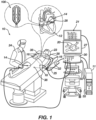
- System 10 includes multiple catheters, which are percutaneously inserted by physician 24 through the patient's 23 vascular system into a chamber or vascular structure of a heart 12.
- a delivery sheath catheter is inserted into the left or right atrium near a desired location in heart 12.
- a plurality of catheters can be inserted into the delivery sheath catheter so as to arrive at the desired location.
- the plurality of catheters may include catheters dedicated for sensing Intracardiac Electrogram (IEGM) signals, catheters dedicated for ablating and/or catheters dedicated for both sensing and ablating.
- An example catheter 14 that is configured for sensing IEGM is illustrated herein.
- Physician 24 brings a distal tip of catheter 14 (i.e., end effector 100) into contact with the heart wall for sensing a target site in heart 12.
- physician 24 would similarly bring a distal end of an ablation catheter to a target site for ablating.
- Catheter 14 is an exemplary catheter that includes one and preferably multiple electrodes optionally distributed over end effector 100 and configured to sense the IEGM signals as described herein.
- Catheter 14 may additionally include a position sensor embedded in or near end effector 100 for tracking position and orientation of end effector 100.
- position sensor is a magnetic based position sensor including multiple magnetic coils for sensing three-dimensional (3D) position and orientation.
- Magnetic based position sensor may be operated together with a location pad 25 including a plurality of magnetic coils 32 configured to generate magnetic fields in a predefined working volume.
- Real time position of end effector 100 of catheter 14 may be tracked based on magnetic fields generated with location pad 25 and sensed by magnetic based position sensor. Details of the magnetic based position sensing technology are described in U.S. Patent Nos. 5,391,199 ; 5,443,489 ; 5,558,091 ; 6,172,499 ; 6,239,724 ; 6,332,089 ; 6,484,118 ; 6,618,612 ; 6,690,963 ; 6,788,967 ; 6,892,091 , each of which are incorporated herein by reference and attached in the Appendix hereto.
- System 10 includes one or more electrode patches 38 positioned for skin contact on patient 23 to establish location reference for location pad 25 as well as impedance-based tracking of electrodes 26.
- impedance-based tracking electrical current is directed toward electrodes and sensed at electrode skin patches 38 so that the location of each electrode can be triangulated via the electrode patches 38. Details of the impedance-based location tracking technology are described in US Patent Nos. 7,536,218 ; 7,756,576 ; 7,848,787 ; 7,869,865 ; and 8,456,182 , each of which are incorporated herein by reference and attached in the Appendix hereto.
- a recorder 11 displays electrograms 21 captured with body surface ECG electrodes 18 and intracardiac electrograms (IEGM) captured with electrodes of catheter 14.
- Recorder 11 may include pacing capability for pacing the heart rhythm and/or may be electrically connected to a standalone pacer.
- System 10 may include an ablation energy generator 50 that is adapted to conduct ablative energy to one or more of electrodes at a distal tip of a catheter configured for ablating.
- Energy produced by ablation energy generator 50 may include, but is not limited to, radiofrequency (RF) energy or pulsed-field ablation (PFA) energy, including monopolar or bipolar high-voltage DC pulses as may be used to effect irreversible electroporation (IRE), or combinations thereof.
- RF radiofrequency
- PFA pulsed-field ablation
- IRE irreversible electroporation
- Patient interface unit (PIU) 30 is an interface configured to establish electrical communication between catheters, electrophysiological equipment, power supply and a workstation 55 for controlling operation of system 10.
- Electrophysiological equipment of system 10 may include for example, multiple catheters, location pad 25, body surface ECG electrodes 18, electrode patches 38, ablation energy generator 50, and recorder 11.
- PIU 30 additionally includes processing capability for implementing real-time computations of location of the catheters and for performing ECG calculations.
- Workstation 55 includes memory, processor unit with memory or storage with appropriate operating software loaded therein, and user interface capability. Workstation 55 may provide multiple functions, optionally including (1) modeling the endocardial anatomy in three-dimensions (3D) and rendering the model or anatomical map 20 for display on a display device 27, (2) displaying on display device 27 activation sequences (or other data) compiled from recorded electrograms 21 in representative visual indicia or imagery superimposed on the rendered anatomical map 20, (3) displaying real-time location and orientation of multiple catheters within the heart chamber, and (5) displaying on display device 27 sites of interest such as places where ablation energy has been applied.
- One commercial product embodying elements of the system 10 is available as the CARTO TM 3 System, available from Biosense Webster, Inc., 31 Technology Drive, Suite 200, Irvine, CA 92618.
- the end effector has a sloped substrate, among other components.
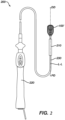
- the disclosed technology includes a system 200 for performing a medical procedure as shown in FIG. 2 .
- the system 200 can include an elongate shaft 230 extending along a longitudinal axis L-L from a proximal end 234 to a distal end 232, an end effector 100 disposed on the distal end 232 of the elongate shaft 230.
- the elongate shaft 230 can be configured to deliver the end effector 100' out of a sheath 210. For simplicity, only a portion of the sheath 210 is shown in FIG. 2 . Note that end effector 100' has an alternative configuration to end effector 100 depending on the use case but the disclosure provided herein is applicable to both embodiments.
- a physician can manipulate the elongate shaft 230 and the end effector 100' with handle 220.
- Appropriate examples for system 200 and its subcomponents such as handle 220, sheath 210, elongate shaft 230, and others not mentioned herein are described in US Patent publication No. 2021/0369339 , which is incorporated herein by reference and included in the Appendix attached hereto.
- System 200 can further include a pull wire (not shown) extending through the elongate shaft 230 and including a distal end (not shown) coupled to a proximal portion 102 (shown in FIG. 3A ) of the end effector 100 or 100'. Details of the manipulation of end effectors via pull wires are described in US Patent Publication No. 2021/0369339 , which is incorporated herein by reference and included in the Appendix attached hereto.
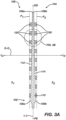
- FIG. 3A shows end effector 100 or 100' in greater detail in a side cross-sectional view.
- the end effector 100 can include a substrate 110 extending along a longitudinal axis L-L from the proximal portion 102 of the end effector 100 or 100' to a distal portion 104 of the end effector 100.
- the substrate 110 can include a longitudinal plane L p with the longitudinal axis L-L running through the longitudinal plane L p .
- the longitudinal plane L p can extend along the longitudinal axis and in a direction in and out of the page when viewing FIG.
- a first face 112 can be disposed on a first side Si of the substrate 110.
- the first face 112 can extend in a direction that is oblique to the longitudinal plane L p (i.e., the first face 112 can extend in a direction that is not parallel nor at a right angle to the longitudinal plane L p ).
- end effector 100 namely the substrate 110
- the electrodes 120, 130 can vary in thickness as well.
- a distance between the first face 112 and the longitudinal plane L p at a proximal end can be greater than a distance between the first face 112 and the longitudinal plane L p at a distal end.
- a second face 114, opposite the first face 112, can be disposed on a second side S 2 of the substrate 110.
- the end effector can further include a first group of electrodes 120 disposed on the first face 112 and a second group of electrodes 130 disposed on the second face 114.
- first face 112 and second face 114 are not necessarily completely planar.
- First face 112 and second face 114 can have undulating profiles, through holes, scallops, and the like, all of which can be included for the purpose of tuning the stiffness and/or the conformability to the tissue of the end effector 100.
- end effector 100 is roughly spatula shaped.
- the end effector 100 can further include a substrate having a hollow profile.
- the end effector 100 can include inserts or frame members made from a composite matrix of materials (metals, polymers, ceramics, etc.) stacked in various orientations (longitudinal, perpendicular, axial, etc.) which can form an array.
- inserts or frame members can be woven, spun, braided, molded, casted, printed (including three-dimensional printing) or manufacturing using any other suitable manufacturing process.
- the second face 114 can be oblique to the longitudinal plane L p . That is to say, the second face 114 can be nonparallel to the longitudinal plane L p and the first face 112.
- the second face 114 can lie at an angle relative to the longitudinal plane L p approximately equal and opposite to the angle at which the first face 112 lies relative to the longitudinal plane L p , such that the second face 114 is a mirror image of the first face 112 taken across the longitudinal plane L p . Stated otherwise, a distance between the second face 114 and the longitudinal plane L p at a proximal end can be greater than a distance between the second face 114 and the longitudinal plane L p at a distal end.
- the angle at which the first face 112 lies relative to the longitudinal plane L p can be different than the angle at which the first face 112 lies relative to the longitudinal plane L p .
- only the first face 112 or the second face 114 can extend in a direction that is oblique to the longitudinal plane L p while the other of the first face 112 or the second face 114 extends in a direction that is approximately parallel to the longitudinal plane L p .
- the end effector 100 can further define a first offset plane P 1 offset from the first face 112 and parallel to the longitudinal plane L p and a second offset plane P 2 offset from second face 114 and parallel to the longitudinal plane L p .
- the first group of electrodes 120 can extend outwardly from the first face 112 to the first offset plane P 1 and the second group of electrodes 130 can extend outwardly from the second face 114 to the second offset plane P 2 .
- the first group of electrodes 120 can be projected from the first face 112 such that, if end effector 100 is rested on a flat surface, the longitudinal plane L p lies parallel to the flat surface.
- the plane P 1 can be offset from the first face 112 and oblique to the longitudinal plane L p such that some or all of the first group of electrodes 120 can be projected from the first face 112 and, if end effector 100 is rested on a flat surface, the first face 112 lies generally parallel to the flat surface. Either of these configurations for the first group of electrodes 120 can be combined with similar configurations of the second group of electrodes 130.
- the disclosed technology includes a nonplanar end effector 100 for a mapping or ablation catheter.
- end effector 100 and substrate 110 may be described as nonplanar, some subcomponents can lie in a flat plane.
- contact surfaces 122 of the first group of electrodes 120 can lie in a flat plane, and a non-conductive flexible material 150 may result in an end effector 100 which as an overall flat outer profile.
- nonplanar as used in relation to the end effector 100 is not meant to exclude these examples.
- the end effector 100 can include a sloped substrate 110 extending along a longitudinal plane L p extending along a longitudinal axis L-L from a proximal end 102 of the end effector 100 to a distal end 104 of the end effector 100.
- the substrate 110 can thin progressively in a direction orthogonal O-O to the longitudinal plane L p .
- Nonplanar end effector 100 can include a first plurality of electrodes 120 disposed on a first face 112 of the sloped substrate 110 and a second plurality of electrodes 130 disposed on a second face 114 of the sloped substrate 110.
- the sloped substrate 110 can be a flexible circuit (flex circuit).
- flexible circuit can be made primarily of polyimide.
- the flexible circuit can include conductive traces connecting the first 120 and second 130 groups of electrodes to components of system 10, for at least the purpose of acquiring signals and delivering energy.
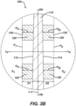
- the first group of electrodes 120 can each include an individual height H I1 from the first face 112 to the first offset plane P 1 .
- the second group of electrodes 130 can each include an individual height H I2 from the second face 114 to the second offset plane P 2 .
- the individual height Hn of the more distal first electrode 120 is taller than the individual height H I1 of the more proximal first electrode 120.
- the individual height H I2 of the more distal second electrode 130 is taller than the individual height H I2 of the more proximal second electrode 130.
- FIG. 3B the individual height Hn of the more distal first electrode 120 is taller than the individual height H I1 of the more proximal first electrode 120.
- the individual height H I2 of the more distal second electrode 130 is taller than the individual height H I2 of the more proximal second electrode 130.
- the individual height Hn of each of the first electrodes can be equal to the individual height H I2 of a respective second electrode 130 positioned similarly in relation to the longitudinal axis, or, in other words, a second electrode 130 which is an equal distance from the proximal end 102 of the end effector 100.
- the first offset plane P 1 can be parallel to the longitudinal plane L p and separated therefrom by a first distance D 1 .
- the second offset plane P 2 can be parallel to the longitudinal plane L p and separated therefrom by a second distance D 2 .
- the second distance D 2 is equal to the first distance D 1 while in other examples the second distance D 2 is different than the first distance D 1 .
- the first plurality of electrodes 120 can include a respective plurality of first contact surfaces 122.
- the second plurality of electrodes 130 can include a respective plurality of second contact surfaces 132.
- the plurality of first contact surfaces 122 and the plurality of second contact surfaces 132 can be parallel to the longitudinal plane L p as shown in FIG. 3B .
- Contact surfaces 122 are the surfaces of electrodes 120 which lie in the first offset plane P 1 and are configured to contact tissue targeted for sensing and/or ablation.
- contact can refer to the component touching tissue or can refer to electrical contact.
- contact surfaces 122 can be coated or otherwise prevented from touching tissue but may still be capable of delivering (e.g., ablation of tissue) or receiving electrical current (e.g., acquisition of physiological signals, such as the propagation of electrical currents through cardiac tissue) passing through the tissue.
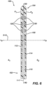
- end effector 100 is symmetrical across longitudinal plane L p and the electrodes 120, 130 are flat against the first face 112 and the second face 114.
- first electrodes 120 and second electrodes 130 extend up to the first offset plane P 1 and the second offset plane P 2 , respectively, each having the same height.
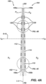
- distal end 106a of the first face 112 is separated from the first offset plane P 1 by a first distal distance D D1 (as shown in FIG. 4B )
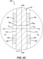
- a proximal end 108a of the first face 112 is separated from the first offset plane P 1 by a first proximal distance D P1 (as shown in FIG.
- the first distal distance D D1 does not equal the first proximal distance D P1 . That is, the first proximal distance D P1 can be greater than the first distal distance D D1 . In some examples, this results in the first group of electrodes 120 having a uniform height and lying flatly against and parallel to the first face 112.
- a distal end 106b of the second face 114 is separated from the second offset plane P 2 by a second distal distance D D2 (as shown in FIG. 4B ), a proximal end 108b of the second face 114 is separated from the second offset plane P 2 by a second proximal distance D P2 (as shown in FIG. 4C ), and the second distal distance D D2 does not equal the second proximal distance D P2 . That is, the second proximal distance D P2 can be greater than the second distal distance D D2 .
- the second group of electrodes 130 can have a uniform height and lie flatly against and parallel to the second face 114. As seen in FIG.
- the plurality of first contact surfaces 122 can be parallel to the first face 112 and the plurality of second contact surfaces 132 can be parallel to the second face 114.
- this can in some examples result in end effector 100 being narrower at the distal end 104 than at the proximal end 102, thus having gradually decreasing stiffness in the distal direction DD.
- This narrowing can increase the ability of end effector 100 to conform to tissue surfaces, thus allowing electrodes 120, 130 to better contact said tissue and more effectively acquire signals and/or deliver ablative energy.
- the first proximal distance D P1 is equal to the second proximal distance D P2
- the first distal distance D D1 is equal to the second distal distance D D2 .
- the first group of electrodes 120 can include at least one first mapping electrode and/or at least one first ablation electrode.
- the second group of electrodes 130 can include at least one second mapping electrode and/or at least one second ablation electrode. Electrodes 120 and 130 can be configured to detect electrophysiological signals or transmit ablative energy (AC or DC) from an energy generator to the tissue according to the various ablation methods previously described (e.g., RF, IRE, etc.).
- ablative energy AC or DC
- FIGs. 3A-4C and the nonplanar nature of end effector 100 improve the ability of the end effector 100 (and thus electrodes 120, 130) to conform to tissue, acquire signals, and deliver energy.
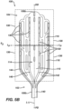
- FIG. 5A illustrates a view of the first side 112 of the end effector.
- the first group of electrodes 120 can be disposed on the first face 112 such that a distal subset 128 of the first group of electrodes 120 is nearer the distal portion 104 than a proximal subset 126 of the first group of electrodes 120.
- the distal subset 128 of the first group of electrodes 120 can include approximately twice as many electrodes as the proximal subset 126 of the first group of electrodes 120. Generally, there can be more first electrodes 120 in the distal subset 128 than in the proximal subset 126.
- the second group of electrodes 130 can be disposed on the second face 114 such that a distal subset 138 of the second group of electrodes 130 is nearer the distal portion 104 than a proximal subset 136 of the second group of electrodes 130 with the distal subset 138 of the second group of electrodes 130 including approximately twice as many electrodes as the proximal subset 136 of the second group of electrodes 130.
- At least a portion of the first group of electrodes 120 can be aligned with at least a portion of the second group of electrodes 130 in a direction O-O orthogonal to the longitudinal plane L p to form respective aligned pairs of first 120 and second 130 electrodes.
- Aligned pairs of electrodes can be aligned generally transverse to the longitudinal axis L-L. Pairs of opposite facing electrodes can be utilized to cancel noise, with one electrode sensing tissue directly and the opposite electrode sensing far-field signals which typically may include noise, as is appreciated by those skilled in the pertinent art.
- FIGs. 5A-5B show a framework 140 lying in the substrate 110 and coplanar with the longitudinal plane L p .
- the framework 140 can include a plurality of tines 142 joined proximate a proximal end 108 of the end effector 100 and extending distally therefrom.
- the plurality of tines 142 can include two outer tines 144 and two inner tines 146, with an outer tine 144 and an inner tine 146 disposed on either side of the longitudinal axis L-L.
- the two inner tines 146 narrow progressively in a distal direction DD.
- the narrowing of the tines 142 can be configured to modulate the bending stiffness of the end effector 100.
- the aligned pairs of first and second electrodes can be aligned with the framework 140 in the orthogonal direction O-O.
- the substrate 110 can further define a plurality of elongate slots 116 lying generally parallel to the longitudinal axis L-L and disposed between each outer tine 144 and inner tine 146.
- Elongate slots 116 can be shaped to modify the bending stiffness and the torsional stiffness (rotation about longitudinal axis L-L) of the end effector 100 to enable it to conform to a tissue surface.
- Framework 140 can be thought of as a forked plurality of stiffness increasing members serving to provide support to end effector 100.
- the framework 140 can be formed from a planar or cylindrical stock of material using any suitable method.
- the framework 140 can be formed by cutting, laser cutting, stamping, etc.
- the substrate 110 can include a flexible circuit.
- the substrate 110 can include a framework, such as framework 140 described above.
- the framework 140 can include nitinol.
- end effector 100 can be at least partially encapsulated by a non-conductive flexible material 150.
- This nonconductive flexible material 150 can serve at least in part to enhance the atraumaticity of the end effector 100 and to protect the subject from sharp edges.
- the flexible non-conductive material 150 can include biocompatible silicone.
- the flexible non-conductive material 150 can include biocompatible flexible polymers, thermoelastic polymer materials, and dielectric materials.
- the flexible non-conductive material 150 can optionally be colored to facilitate laser cutting.
- the framework 140 can be affixed to the substrate 110 by non-conductive flexible encapsulating material 150. Contact surfaces 122 and 132 can be exposed to the ambient environment through the non-conductive flexible material 150.
- the non-conductive flexible material 150 can be thickened at various points in the longitudinal direction L-L and the orthogonal direction O-O to have a profile that compliments the variable stiffness of the substrate 110.
- the framework 150 can be shaped such that it contributes more to the overall stiffness of the end effector 100 in the torsional stiffness (rotation about the longitudinal axis L-L) than to the longitudinal direction L-L.
- the flexible material 150 can be formed such that it encourages folding/creasing of the end effector between columns, rows, and/or portions (for example portions 126, 128, 136, and 138 shown in FIGs. 5A and 5B ) or electrodes.
- Flexible non-conductive material 150 can also form a blunt distal end 104.
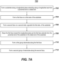
- FIGs. 7A-7C shows a method 700 of providing a stiffened flexible end effector.
- Method 700 can in some examples provide end effector 100 as detailed above, with all of its components and subcomponents.
- method 700 can include forming 702 a substrate along a longitudinal plane extending along a longitudinal axis from a proximal end to a distal end, forming 704 a first face on a first side of the substrate, forming 706 a second face on a second side, opposite the first side, of the substrate, sloping 708 the first face toward the longitudinal plane as the first face extends from the proximal end of the substrate to the distal end of the substrate, forming 710 a first group electrodes along the first face, and forming 712 a second group of electrodes along the second face.
- FIG. 7B shows the method further including sloping 709 the second face toward the longitudinal plane as the second face extends from the proximal end of the substrate to the distal end of the substrate.
- the method can further include sizing 714 each electrode of the first group of electrodes to include a first electrode height extending from the first face to a first offset plane.
- Method 700 can include sizing 716 each electrode of the second group of electrodes to include a second electrode height extending from the second face to a second offset plane.
- forming 710 the first group of electrodes can include dispersing 711 the first group of electrodes such that a distal subset of the first group of electrodes is nearer a distal portion than a proximal subset of the first group of electrodes, the distal subset of the first group of electrodes including approximately twice as many electrodes as the proximal subset of the first group of electrodes.
- Method 700 can further include forming 712 the second group of electrodes.
- Forming 712 the second electrodes 712 can include dispersing 713 the second group of electrodes such that a distal subset of the second group of electrodes is nearer the distal portion than a proximal subset of the second group of electrodes, the distal subset of the second group of electrodes including approximately twice as many electrodes as the proximal subset of the second group of electrodes.
- the method 700 can include aligning 718 at least a portion of the first group of electrodes with at least a portion of the second group of electrodes in a direction orthogonal to the longitudinal plane to form respective aligned pairs of first and second electrodes.
- Method 700 can include forming 720 a framework lying substantially in the longitudinal plane and aligning 722 the aligned pairs of first and second electrodes with the framework in the orthogonal direction.
- Method 700 can further include encapsulating 724 the end effector with a non-conductive flexible material.
- the method 700 just described can include more or fewer steps or features than those described. Furthermore, the steps or features can be performed in different orders and should not be construed as being required to be performed in any particular order.
Landscapes
- Health & Medical Sciences (AREA)
- Life Sciences & Earth Sciences (AREA)
- Surgery (AREA)
- Engineering & Computer Science (AREA)
- General Health & Medical Sciences (AREA)
- Public Health (AREA)
- Biomedical Technology (AREA)
- Heart & Thoracic Surgery (AREA)
- Medical Informatics (AREA)
- Molecular Biology (AREA)
- Veterinary Medicine (AREA)
- Animal Behavior & Ethology (AREA)
- Physics & Mathematics (AREA)
- Nuclear Medicine, Radiotherapy & Molecular Imaging (AREA)
- Pathology (AREA)
- Biophysics (AREA)
- Otolaryngology (AREA)
- Cardiology (AREA)
- Plasma & Fusion (AREA)
- Dentistry (AREA)
- Mechanical Engineering (AREA)
- Physiology (AREA)
- Surgical Instruments (AREA)
- Measurement And Recording Of Electrical Phenomena And Electrical Characteristics Of The Living Body (AREA)
Applications Claiming Priority (1)
| Application Number | Priority Date | Filing Date | Title |
|---|---|---|---|
| US18/357,828 US20250032103A1 (en) | 2023-07-24 | 2023-07-24 | Catheter end effector with nonplanar substrate |
Publications (1)
| Publication Number | Publication Date |
|---|---|
| EP4497404A1 true EP4497404A1 (fr) | 2025-01-29 |
Family
ID=91966609
Family Applications (1)
| Application Number | Title | Priority Date | Filing Date |
|---|---|---|---|
| EP24190193.3A Pending EP4497404A1 (fr) | 2023-07-24 | 2024-07-23 | Effecteur terminal de cathéter avec substrat non plan |
Country Status (5)
| Country | Link |
|---|---|
| US (1) | US20250032103A1 (fr) |
| EP (1) | EP4497404A1 (fr) |
| JP (1) | JP2025017349A (fr) |
| CN (1) | CN119344739A (fr) |
| IL (1) | IL314444A (fr) |
Citations (19)
| Publication number | Priority date | Publication date | Assignee | Title |
|---|---|---|---|---|
| US5391199A (en) | 1993-07-20 | 1995-02-21 | Biosense, Inc. | Apparatus and method for treating cardiac arrhythmias |
| US5558091A (en) | 1993-10-06 | 1996-09-24 | Biosense, Inc. | Magnetic determination of position and orientation |
| US6172499B1 (en) | 1999-10-29 | 2001-01-09 | Ascension Technology Corporation | Eddy current error-reduced AC magnetic position measurement system |
| US6239724B1 (en) | 1997-12-30 | 2001-05-29 | Remon Medical Technologies, Ltd. | System and method for telemetrically providing intrabody spatial position |
| US6332089B1 (en) | 1996-02-15 | 2001-12-18 | Biosense, Inc. | Medical procedures and apparatus using intrabody probes |
| US6484118B1 (en) | 2000-07-20 | 2002-11-19 | Biosense, Inc. | Electromagnetic position single axis system |
| US6618612B1 (en) | 1996-02-15 | 2003-09-09 | Biosense, Inc. | Independently positionable transducers for location system |
| US6690963B2 (en) | 1995-01-24 | 2004-02-10 | Biosense, Inc. | System for determining the location and orientation of an invasive medical instrument |
| US6892091B1 (en) | 2000-02-18 | 2005-05-10 | Biosense, Inc. | Catheter, method and apparatus for generating an electrical map of a chamber of the heart |
| US7536218B2 (en) | 2005-07-15 | 2009-05-19 | Biosense Webster, Inc. | Hybrid magnetic-based and impedance-based position sensing |
| US7756576B2 (en) | 2005-08-26 | 2010-07-13 | Biosense Webster, Inc. | Position sensing and detection of skin impedance |
| US7848787B2 (en) | 2005-07-08 | 2010-12-07 | Biosense Webster, Inc. | Relative impedance measurement |
| US7869865B2 (en) | 2005-01-07 | 2011-01-11 | Biosense Webster, Inc. | Current-based position sensing |
| US20110040167A1 (en) * | 2009-08-14 | 2011-02-17 | Boston Scientific Scimed, Inc. | Systems and methods for making and using medical ablation systems and having mapping catheters with improved anchoring ability |
| US8456182B2 (en) | 2008-09-30 | 2013-06-04 | Biosense Webster, Inc. | Current localization tracker |
| US20180193089A1 (en) * | 2017-01-09 | 2018-07-12 | Biosense Webster (Israel) Ltd. | Catheter with supporting structure having variable dimensions |
| US20210369339A1 (en) | 2020-05-29 | 2021-12-02 | Biosense Webster (Israel) Ltd. | Electrode apparatus for diagnosis of arrhythmias |
| EP4201357A1 (fr) * | 2021-12-27 | 2023-06-28 | Biosense Webster (Israel) Ltd. | Effecteur terminal de cathéter à cadre élastique et intérieur flexible |
| EP4205684A1 (fr) * | 2021-12-31 | 2023-07-05 | Biosense Webster (Israel) Ltd | Appareil à électrode reconfigurable pour le diagnostic d'arythmies |
-
2023
- 2023-07-24 US US18/357,828 patent/US20250032103A1/en active Pending
-
2024
- 2024-07-22 IL IL314444A patent/IL314444A/en unknown
- 2024-07-23 EP EP24190193.3A patent/EP4497404A1/fr active Pending
- 2024-07-23 JP JP2024117592A patent/JP2025017349A/ja active Pending
- 2024-07-24 CN CN202410997597.5A patent/CN119344739A/zh active Pending
Patent Citations (21)
| Publication number | Priority date | Publication date | Assignee | Title |
|---|---|---|---|---|
| US5443489A (en) | 1993-07-20 | 1995-08-22 | Biosense, Inc. | Apparatus and method for ablation |
| US5391199A (en) | 1993-07-20 | 1995-02-21 | Biosense, Inc. | Apparatus and method for treating cardiac arrhythmias |
| US5558091A (en) | 1993-10-06 | 1996-09-24 | Biosense, Inc. | Magnetic determination of position and orientation |
| US6690963B2 (en) | 1995-01-24 | 2004-02-10 | Biosense, Inc. | System for determining the location and orientation of an invasive medical instrument |
| US6332089B1 (en) | 1996-02-15 | 2001-12-18 | Biosense, Inc. | Medical procedures and apparatus using intrabody probes |
| US6618612B1 (en) | 1996-02-15 | 2003-09-09 | Biosense, Inc. | Independently positionable transducers for location system |
| US6788967B2 (en) | 1997-05-14 | 2004-09-07 | Biosense, Inc. | Medical diagnosis, treatment and imaging systems |
| US6239724B1 (en) | 1997-12-30 | 2001-05-29 | Remon Medical Technologies, Ltd. | System and method for telemetrically providing intrabody spatial position |
| US6172499B1 (en) | 1999-10-29 | 2001-01-09 | Ascension Technology Corporation | Eddy current error-reduced AC magnetic position measurement system |
| US6892091B1 (en) | 2000-02-18 | 2005-05-10 | Biosense, Inc. | Catheter, method and apparatus for generating an electrical map of a chamber of the heart |
| US6484118B1 (en) | 2000-07-20 | 2002-11-19 | Biosense, Inc. | Electromagnetic position single axis system |
| US7869865B2 (en) | 2005-01-07 | 2011-01-11 | Biosense Webster, Inc. | Current-based position sensing |
| US7848787B2 (en) | 2005-07-08 | 2010-12-07 | Biosense Webster, Inc. | Relative impedance measurement |
| US7536218B2 (en) | 2005-07-15 | 2009-05-19 | Biosense Webster, Inc. | Hybrid magnetic-based and impedance-based position sensing |
| US7756576B2 (en) | 2005-08-26 | 2010-07-13 | Biosense Webster, Inc. | Position sensing and detection of skin impedance |
| US8456182B2 (en) | 2008-09-30 | 2013-06-04 | Biosense Webster, Inc. | Current localization tracker |
| US20110040167A1 (en) * | 2009-08-14 | 2011-02-17 | Boston Scientific Scimed, Inc. | Systems and methods for making and using medical ablation systems and having mapping catheters with improved anchoring ability |
| US20180193089A1 (en) * | 2017-01-09 | 2018-07-12 | Biosense Webster (Israel) Ltd. | Catheter with supporting structure having variable dimensions |
| US20210369339A1 (en) | 2020-05-29 | 2021-12-02 | Biosense Webster (Israel) Ltd. | Electrode apparatus for diagnosis of arrhythmias |
| EP4201357A1 (fr) * | 2021-12-27 | 2023-06-28 | Biosense Webster (Israel) Ltd. | Effecteur terminal de cathéter à cadre élastique et intérieur flexible |
| EP4205684A1 (fr) * | 2021-12-31 | 2023-07-05 | Biosense Webster (Israel) Ltd | Appareil à électrode reconfigurable pour le diagnostic d'arythmies |
Also Published As
| Publication number | Publication date |
|---|---|
| US20250032103A1 (en) | 2025-01-30 |
| CN119344739A (zh) | 2025-01-24 |
| JP2025017349A (ja) | 2025-02-05 |
| IL314444A (en) | 2025-02-01 |
Similar Documents
| Publication | Publication Date | Title |
|---|---|---|
| US20240215893A1 (en) | Double-sided encapsulated planar catheter | |
| EP4497405A2 (fr) | Cathéter plan encapsulé double face avec polymère d'encapsulation | |
| US20240390056A1 (en) | End effector having elongated support member with curved electrode landing region | |
| EP4497404A1 (fr) | Effecteur terminal de cathéter avec substrat non plan | |
| EP4473926A1 (fr) | Cathéter plan encapsulé double face | |
| US20250194983A1 (en) | Medical probe with slitted tube and electrodes | |
| EP4541303A1 (fr) | Électrodes de circuit flexible pour cathéter lasso | |
| EP4574071A2 (fr) | Cathéters panier simplifiés à multiples entretoises | |
| US20250099168A1 (en) | Medical device with a monolithic spine framework | |
| US20240216054A1 (en) | Systems and methods for cylindrical cage mapping and ablation catheters comprising flexible circuits | |
| EP4461247A1 (fr) | Connecteur électrique pour un dispositif de cathéter | |
| US20250195132A1 (en) | Medical probe with spines for pulmonary vein isolation | |
| US20260013771A1 (en) | Collapsible planar catheter | |
| US20250099160A1 (en) | Medical device with an end effector including connecting hubs and an electrode array | |
| EP4473928A1 (fr) | Ensembles panier extensibles et ensembles panier extensibles avec soulagement de contrainte de fil d'électrode | |
| EP4393426A2 (fr) | Cathéter à électrodes multiples avec substrat entrelacé | |
| EP4578416A2 (fr) | Ensembles cathéter et électrode à panier configurés pour un contact tissulaire amélioré | |
| US20240206965A1 (en) | Deformed spine electrode basket and methods of the same | |
| EP4606334A1 (fr) | Electrodes annulaires modulaires |
Legal Events
| Date | Code | Title | Description |
|---|---|---|---|
| PUAI | Public reference made under article 153(3) epc to a published international application that has entered the european phase |
Free format text: ORIGINAL CODE: 0009012 |
|
| STAA | Information on the status of an ep patent application or granted ep patent |
Free format text: STATUS: THE APPLICATION HAS BEEN PUBLISHED |
|
| AK | Designated contracting states |
Kind code of ref document: A1 Designated state(s): AL AT BE BG CH CY CZ DE DK EE ES FI FR GB GR HR HU IE IS IT LI LT LU LV MC ME MK MT NL NO PL PT RO RS SE SI SK SM TR |
|
| STAA | Information on the status of an ep patent application or granted ep patent |
Free format text: STATUS: REQUEST FOR EXAMINATION WAS MADE |
|
| 17P | Request for examination filed |
Effective date: 20250521 |