EP4497516A1 - Procédé de fabrication d'un composant électrique ou électronique sous montage d'un composant électrique ou électronique avec une enveloppe métallique entourant ledit composant - Google Patents
Procédé de fabrication d'un composant électrique ou électronique sous montage d'un composant électrique ou électronique avec une enveloppe métallique entourant ledit composant Download PDFInfo
- Publication number
- EP4497516A1 EP4497516A1 EP24186729.0A EP24186729A EP4497516A1 EP 4497516 A1 EP4497516 A1 EP 4497516A1 EP 24186729 A EP24186729 A EP 24186729A EP 4497516 A1 EP4497516 A1 EP 4497516A1
- Authority
- EP
- European Patent Office
- Prior art keywords
- auxiliary sleeve
- blank
- casing
- pressing
- electronic component
- Prior art date
- Legal status (The legal status is an assumption and is not a legal conclusion. Google has not performed a legal analysis and makes no representation as to the accuracy of the status listed.)
- Pending
Links
Images


Classifications
-
- H—ELECTRICITY
- H01—ELECTRIC ELEMENTS
- H01R—ELECTRICALLY-CONDUCTIVE CONNECTIONS; STRUCTURAL ASSOCIATIONS OF A PLURALITY OF MUTUALLY-INSULATED ELECTRICAL CONNECTING ELEMENTS; COUPLING DEVICES; CURRENT COLLECTORS
- H01R4/00—Electrically-conductive connections between two or more conductive members in direct contact, i.e. touching one another; Means for effecting or maintaining such contact; Electrically-conductive connections having two or more spaced connecting locations for conductors and using contact members penetrating insulation
- H01R4/10—Electrically-conductive connections between two or more conductive members in direct contact, i.e. touching one another; Means for effecting or maintaining such contact; Electrically-conductive connections having two or more spaced connecting locations for conductors and using contact members penetrating insulation effected solely by twisting, wrapping, bending, crimping, or other permanent deformation
- H01R4/18—Electrically-conductive connections between two or more conductive members in direct contact, i.e. touching one another; Means for effecting or maintaining such contact; Electrically-conductive connections having two or more spaced connecting locations for conductors and using contact members penetrating insulation effected solely by twisting, wrapping, bending, crimping, or other permanent deformation by crimping
- H01R4/20—Electrically-conductive connections between two or more conductive members in direct contact, i.e. touching one another; Means for effecting or maintaining such contact; Electrically-conductive connections having two or more spaced connecting locations for conductors and using contact members penetrating insulation effected solely by twisting, wrapping, bending, crimping, or other permanent deformation by crimping using a crimping sleeve
-
- B—PERFORMING OPERATIONS; TRANSPORTING
- B21—MECHANICAL METAL-WORKING WITHOUT ESSENTIALLY REMOVING MATERIAL; PUNCHING METAL
- B21D—WORKING OR PROCESSING OF SHEET METAL OR METAL TUBES, RODS OR PROFILES WITHOUT ESSENTIALLY REMOVING MATERIAL; PUNCHING METAL
- B21D39/00—Application of procedures in order to connect objects or parts, e.g. coating with sheet metal otherwise than by plating; Tube expanders
- B21D39/04—Application of procedures in order to connect objects or parts, e.g. coating with sheet metal otherwise than by plating; Tube expanders of tubes with tubes; of tubes with rods
- B21D39/046—Connecting tubes to tube-like fittings
-
- B—PERFORMING OPERATIONS; TRANSPORTING
- B21—MECHANICAL METAL-WORKING WITHOUT ESSENTIALLY REMOVING MATERIAL; PUNCHING METAL
- B21D—WORKING OR PROCESSING OF SHEET METAL OR METAL TUBES, RODS OR PROFILES WITHOUT ESSENTIALLY REMOVING MATERIAL; PUNCHING METAL
- B21D39/00—Application of procedures in order to connect objects or parts, e.g. coating with sheet metal otherwise than by plating; Tube expanders
- B21D39/04—Application of procedures in order to connect objects or parts, e.g. coating with sheet metal otherwise than by plating; Tube expanders of tubes with tubes; of tubes with rods
- B21D39/048—Application of procedures in order to connect objects or parts, e.g. coating with sheet metal otherwise than by plating; Tube expanders of tubes with tubes; of tubes with rods using presses for radially crimping tubular elements
-
- B—PERFORMING OPERATIONS; TRANSPORTING
- B23—MACHINE TOOLS; METAL-WORKING NOT OTHERWISE PROVIDED FOR
- B23P—METAL-WORKING NOT OTHERWISE PROVIDED FOR; COMBINED OPERATIONS; UNIVERSAL MACHINE TOOLS
- B23P11/00—Connecting or disconnecting metal parts or objects by metal-working techniques not otherwise provided for
- B23P11/005—Connecting or disconnecting metal parts or objects by metal-working techniques not otherwise provided for by expanding or crimping
-
- B—PERFORMING OPERATIONS; TRANSPORTING
- B25—HAND TOOLS; PORTABLE POWER-DRIVEN TOOLS; MANIPULATORS
- B25B—TOOLS OR BENCH DEVICES NOT OTHERWISE PROVIDED FOR, FOR FASTENING, CONNECTING, DISENGAGING, OR HOLDING
- B25B27/00—Hand tools, specially adapted for fitting together or separating parts or objects whether or not involving some deformation, not otherwise provided for
- B25B27/02—Hand tools, specially adapted for fitting together or separating parts or objects whether or not involving some deformation, not otherwise provided for for connecting objects by press fit or detaching same
- B25B27/10—Hand tools, specially adapted for fitting together or separating parts or objects whether or not involving some deformation, not otherwise provided for for connecting objects by press fit or detaching same inserting fittings into hoses
Definitions
- the present invention relates to a method for producing an electrical or electronic component.
- the present invention relates to such a method in which - as part of the production of the electrical or electronic component in question - an electrical or electronic component is fitted with a metallic casing surrounding it.
- the present invention relates to a method for fitting an electrical or electronic component that is cylindrical at least in sections with a metallic casing that closely surrounds it.
- the DE 101 56 299 A1 discloses a connection arrangement and a method for connecting a connection element to an electrical conductor.
- an electrical cable which has a conductor surrounded by an insulating sheath
- the insulating sheath is removed at the end and the corresponding end of the conductor is inserted into the through hole of a hollow cylindrical connection element.
- This is then pressed onto the conductor by radial deformation on the one hand and on the other hand - in the area protruding over the end of the conductor - is deformed to reduce the cross-section to form a plug pin.
- the DE 103 36 408 A1 discloses a method for connecting a contact element to a cable.
- an electrical cable which has a conductor surrounded by an insulating sheath
- the insulating sheath is removed at the end and the corresponding end of the conductor is inserted into the insertion hole of a sleeve-shaped connecting element.
- This is then formed by radial deformation (round swaging) onto the inserted conductor before the connecting element is finally welded to the contact element by means of ultrasonic welding.
- the WO 2019/199 758 A1 relates to the pressing of the sleeve of a connecting element onto the exposed end section of the conductor of an electrical cable.
- the tool used for said pressing has a die with a ten-sided inner contour.
- a radial press for the radial deformation of workpieces.
- This has eight base jaws arranged around a press axis, which can be moved radially inwards and outwards synchronously by means of a drive unit.
- Interchangeable press jaws can be attached to these, which have a pressing surface on the inside that is specifically adapted to the workpiece to be pressed.
- the present invention has set itself the task of providing a way in which, with regard to the subject matter set out at the outset, namely the assembly of an electrical or electronic component that is at least partially cylindrical with a metallic jacket that tightly surrounds it, good results in the respect outlined above can be achieved with comparatively little manufacturing effort.
- the invention makes it possible to use established, reliable and highly precise radial presses for equipping an electrical or electronic component that is at least partially cylindrical with a metallic casing that surrounds it tightly, as they are manufactured and sold in a wide variety of designs by Uniflex-Hydraulik GmbH, DE-61184 Karben and are also known from extensive patent literature (see, for example, DE 41 35 465 A1 , DE 199 12 976 A1 and DE 198 17 882 B4 concerning radial presses in so-called “yoke press” design, DE 101 49 924 A1 concerning radial presses in so-called “hollow piston press” design and DE 28 44 475 A1 , DE 36 11 253 A1 , DE 100 47 025 C2 and DE 33 31 721 A1 concerning radial presses of other constructions).
- auxiliary sleeve used in the process according to the invention when deforming the casing blank in order to convert it into a casing that fits tightly around the electrical or electronic component, which extends between the pressing jaws of the pressing tool of the radial press and the casing blank, surrounding the latter, effectively counteracts the formation of burrs or webs, which, without the use of said auxiliary sleeve, would be caused by material of the casing blank displaced during the pressing process. whose surface would be created between two adjacent pressing jaws.
- the application of the present invention makes it possible to achieve a quality of the surface of the finished electrical or electronic component without reworking the surface, which could only be achieved by means of complex reworking without the use of an auxiliary sleeve according to the invention.
- the moment at which the shell blank comes into contact with the electrical or electronic component during its deformation can be detected particularly precisely by a correspondingly sharp-edged increase in force or pressure in the drive unit of the radial press.
- This allows particularly precise control of the radial press in the sense of a workpiece-specific break or a workpiece-specific termination of the closing movement.
- This protects the electrical or electronic component from mechanical overload, which is an invaluable manufacturing advantage, especially for electrical and electronic components with (typically brittle) ceramic structures.
- the method according to the invention can be used, which is characterized by closing the pressing tool several times in succession, whereby between two closing processes the pressing tool is at least partially opened and the casing blank deformed in the previous closing process or the casing produced from the casing blank is rotated relative to the auxiliary sleeve.
- the burr or web created in the first or previous closing process comes to lie under the non-slotted area of the auxiliary sleeve for the second or subsequent closing process, whereby the burr or web is leveled out again.
- the pressing tool is partially opened between the two closing processes in such a way, i.e. to just the right extent, that the pressing jaws continue to rest on the auxiliary sleeve, but lift it away from the casing blank that was plastically deformed in the previous closing process or the casing that emerged from the casing blank.
- the pressing jaws then hold the auxiliary sleeve, meaning that the intermediate product consisting of the electrical or electronic component and the partially deformed casing blank (or the casing that emerged from the casing blank) can be easily rotated around its axis (for example by 180°) in the auxiliary sleeve - held in place by the pressing jaws - without the need to hold the auxiliary sleeve by hand or in any other way, before the second or further closing process of the radial press is initiated.
- auxiliary sleeve As far as the auxiliary sleeve is concerned, it is particularly advantageous if it is made of spring steel. This is because the elastic resilience of the auxiliary sleeve, such that after the (plastic) deformation of the casing blank, it springs back completely when the radial press is opened and assumes its original shape, is crucial from two points of view. The finished electrical or electronic component can be easily removed from the auxiliary sleeve; and this can be kept ready for the next use without any reworking.
- the inner surface of the auxiliary sleeve which is in contact with the jacket blank during the forming process, is preferably ideally smooth and free of roughness for typical applications of the present invention. However, it can also have specifically defined elevations and/or depressions in order to to imprint corresponding depressions or elevations on the surface of the jacket blank during the forming process in the radial press.
- an auxiliary sleeve - in this case one that protrudes from the pressing tool at least on one side - which is not slotted along its entire length in an axial extension, but in which the slot ends at at least one end region of the auxiliary sleeve in front of its front face.
- the use of an auxiliary sleeve that is slotted along its entire length in an axial extension proves to be advantageous.
- a first preferred development of the present invention is characterized in that an auxiliary sleeve is used with a slot that is generally oriented parallel to its axis.
- This is a particularly simple variant in terms of manufacturing technology. In terms of manufacturing technology, it may be somewhat more demanding, but - from the perspective of a voltage distribution that is as homogeneous as possible within the electrical or electronic component to be manufactured - it has advantages in terms of function.
- a slot generally running along a helical line. The pitch of the helical line is advantageously selected such that the slot on the surface of the auxiliary sleeve completes at least one complete revolution (360°), particularly preferably at least two complete revolutions (720°).
- auxiliary sleeves can be used in which the edges that delimit the slot are designed to be corrugated in a corresponding manner to one another.
- auxiliary sleeves can be used in which the two edges that delimit the slot have interlocking finger profiles with alternately overlapping fingers; the possibility of radially narrowing the auxiliary sleeve provided by the "slot" is thus divided into a plurality of slot sections that are offset from one another in the circumferential direction.
- the auxiliary sleeve being designed with a spiral slot that generally runs along a helical line (see above)
- a stepped design of the two edges that delimit the slot with overlapping steps can be very advantageous, depending on the pitch of the helical line.
- the space provided by the "slot" Possibility of radial narrowing of the auxiliary sleeve divided into a plurality of slot sections offset from one another in the circumferential direction.
- Auxiliary sleeves with a spiral slot that generally runs along a helical line can also be used with very good results for most common applications, with the edges delimiting the slot being spiraled parallel to one another to define a helical gap.
- This design is characterized by being particularly easy to manufacture - by winding from a sheet metal strip made of spring steel, for example.
- the edges of the auxiliary sleeve that delimit the slot can be beveled in such a way that they overlap or cover each other in the circumferential direction.
- the above explanations regarding the geometric or structural design of the auxiliary sleeve refer to its stress-free state, i.e. the state that occurs in the absence of external forces (apart from gravity).
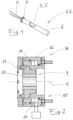
- the electrical component 1 illustrated in the form of a temperature sensor 2 comprises, in a manner known per se, an electrical component 5 designed as a sensor element 3 and having connecting wires 4 of cylindrical shape. This is equipped with a casing 6 in the sense that it is tightly surrounded by a metallic casing 6. For the subsequent correct positioning of the temperature sensor 2 in a hole provided in a device part, the casing 6 has a collar 7.
- a commercially available radial press is used, as shown in an axial section in Fig. 2
- the Fig. 2 illustrated, as such known radial press is in the DE 28 44 475 A1 extensively described and explained. For this reason and in particular because the structural details of the radial press are not important here, a detailed description is unnecessary.
- the radial press 8 has a pressing tool 9 with eight pressing jaws 10, which can be moved synchronously radially in the direction of the pressing axis X by means of a drive unit 15 - here hydraulic, comprising an annular piston 14 which can be acted upon via an annular hydraulic working chamber 11, can be displaced in the housing 12 along the pressing axis X and has control surfaces 13 inclined with respect to the pressing axis X.
- a drive unit 15 - here hydraulic comprising an annular piston 14 which can be acted upon via an annular hydraulic working chamber 11, can be displaced in the housing 12 along the pressing axis X and has control surfaces 13 inclined with respect to the pressing axis X.
- Fig. 2 shows one possible design of the radial press by way of example only. All known and commercially available radial presses are suitable for implementing the present invention, namely all radial presses from Uniflex-Hydraulik GmbH, DE-61184 Karben.
- Fig. 3 shows (schematically, ie not necessarily to scale) the situation before the start of the forming process carried out in the radial press 8.
- the electrical component 5 is housed in a surrounding jacket blank 16 which is cylindrical apart from the collar 7. There is play between the electrical component 5 and the jacket blank 16; in other words, the jacket blank 16 has an excess size compared to the electrical component 5, so that the latter is loosely inserted into the jacket blank 16.
- the jacket blank 16 consists of a plastically deformable metallic material.
- the jacket blank 16 is in turn accommodated in an auxiliary sleeve 17 made of spring steel which surrounds it.
- This auxiliary sleeve 17 - which is slotted in the axial direction and elastically resilient in the radial direction (cf. Figures 5-7 ) has an excess dimension compared to the jacket blank 16; it thus surrounds the jacket blank 16 loosely, ie with play.
- Fig. 4 shows the situation at the end of the closing process of the pressing tool 9.
- the pressing jaws 10 are successively placed on the auxiliary sleeve 17, a first elastic radial narrowing of the auxiliary sleeve 17 until it rests on the jacket blank 16 and a continued elastic radial narrowing of the auxiliary sleeve 17 with simultaneous plastic radial narrowing of the jacket blank 16 until it rests - as jacket 6 - on the electrical component 5 (cf. Fig. 4 ) .
- the elastically-spring-constricted auxiliary sleeve 17 lifts off the jacket 6 that has been produced from the jacket blank 16 by plastic deformation.
- the pressing jaws 10 lift off the auxiliary sleeve 17 as the pressing tool 9 continues to open.
- the electrical component 1 - consisting of the electrical component 5 equipped with the tight-fitting jacket 6 - and the auxiliary sleeve 17 can be removed (simultaneously or one after the other) from the pressing tool 9.
- the electrical component 1 and the auxiliary sleeve 17 are removed from the opened pressing tool 9 at the same time, the electrical component 1 is then removed separately from the auxiliary sleeve 17.
- FIGS 5-8 show four preferred embodiments of an elastic-spring auxiliary sleeve 17 made of spring steel. All four auxiliary sleeve designs are each axially extending over their entire length slotted; the respective slot 18 thus extends from one end face of the auxiliary sleeve 17 to the other.
- the respective slot 18a, 18b is generally oriented parallel to the axis Y of the auxiliary sleeve 17a, 17b.
- the auxiliary sleeves 17c and 17d have Figures 7 and 8 via a generally helical slot 18c or 18d, ie the slot 18c, 18d generally runs along a helical line.
- FIGS 5-7 illustrate three profiles of the edges 19, 20 of the respective auxiliary sleeve 17 which delimit the respective slot 18 and which are superimposed on the general course of the slot 18.
- the two edges 19a, 20a of the auxiliary sleeve 17a that delimit the slot are designed to be corrugated in a corresponding manner.
- Fig. 6 In the embodiment shown, the two edges 19b, 20b of the auxiliary sleeve 17b that delimit the slot 18b are provided with interlocking finger profiles 21 with alternately overlapping fingers 22.
- the two edges 19c, 20c delimiting the slot 18c are stepped with overlapping steps 23, 24.
- edges 19d, 20d delimiting the slot 18d are spirally wound parallel to one another; they delimit a continuous helical gap of defined width.
- All slot variants allow a defined radial narrowing of the respective auxiliary sleeve 17a, 17b, 17c or 17d.
Landscapes
- Engineering & Computer Science (AREA)
- Mechanical Engineering (AREA)
- Forging (AREA)
- Manufacturing Of Electrical Connectors (AREA)
Applications Claiming Priority (1)
| Application Number | Priority Date | Filing Date | Title |
|---|---|---|---|
| DE102023119673.1A DE102023119673A1 (de) | 2023-07-25 | 2023-07-25 | Verfahren zur Herstellung eines elektrischen oder elektronischen Bauteils |
Publications (1)
| Publication Number | Publication Date |
|---|---|
| EP4497516A1 true EP4497516A1 (fr) | 2025-01-29 |
Family
ID=91853583
Family Applications (1)
| Application Number | Title | Priority Date | Filing Date |
|---|---|---|---|
| EP24186729.0A Pending EP4497516A1 (fr) | 2023-07-25 | 2024-07-05 | Procédé de fabrication d'un composant électrique ou électronique sous montage d'un composant électrique ou électronique avec une enveloppe métallique entourant ledit composant |
Country Status (3)
| Country | Link |
|---|---|
| US (1) | US20250038429A1 (fr) |
| EP (1) | EP4497516A1 (fr) |
| DE (1) | DE102023119673A1 (fr) |
Citations (15)
| Publication number | Priority date | Publication date | Assignee | Title |
|---|---|---|---|---|
| US2795769A (en) * | 1947-10-24 | 1957-06-11 | Amp Inc | Electrical connection and method |
| DE2844475A1 (de) | 1978-10-12 | 1980-04-24 | Peter Ing Grad Schroeck | Radialpresse fuer werkstuecke mit zylindrischer aussenflaeche mit mehreren, im kreis angeordneten pressbacken |
| DE3331721A1 (de) | 1983-09-02 | 1985-03-21 | Peter Ing.(grad.) 6380 Bad Homburg Schröck | Radialpresse fuer werkstuecke mit zylindrischer aussenflaeche |
| DE3611253A1 (de) | 1986-04-04 | 1987-10-08 | Peter Dipl Ing Schroeck | Radialpresse |
| DE4135465A1 (de) | 1991-10-28 | 1993-04-29 | Schroeck Peter Dipl Ing Fh | Radialpresse mit zwei radial gegeneinander beweglichen pressenjochen |
| DE29820129U1 (de) * | 1998-11-12 | 2000-05-04 | Pfeifer Seil- und Hebetechnik GmbH & Co, 87700 Memmingen | Preßklemme und Seilschlaufe, beziehungsweise Seil mit einer solchen Preßklemme |
| DE19912976A1 (de) | 1999-03-23 | 2000-09-28 | Uniflex Hydraulik Gmbh | Radialpresse |
| DE10156299A1 (de) | 2000-11-17 | 2002-07-18 | Yazaki Corp | Verbindungsanordnung und Verfahren zum Verbinden eines Anschlußenelements mit einem elektrischen Leiter |
| DE10047025C2 (de) | 2000-09-22 | 2002-11-21 | Uniflex Hydraulik Gmbh | Radialpresse |
| DE10149924A1 (de) | 2001-10-10 | 2003-04-30 | Uniflex Hydraulik Gmbh | Radialpresse |
| DE10336408A1 (de) | 2002-08-07 | 2004-04-15 | Yazaki Corp. | Verfahren zum Verbinden eines Kontaktelements mit einem Kabel |
| DE19547592B4 (de) * | 1995-12-20 | 2005-03-24 | Contitech Schlauch Gmbh | Preßvorrichtung zum konzentrischen Kaltpressen eines rohr- oder ringförmigen Metallkörpers |
| DE19817882B4 (de) | 1998-04-22 | 2005-08-18 | Uniflex-Hydraulik Gmbh | Radialpresse |
| DE102017108399A1 (de) | 2017-04-20 | 2018-10-25 | Uniflex-Hydraulik Gmbh | Radialpresse |
| WO2019199758A1 (fr) | 2018-04-09 | 2019-10-17 | Hubbell Incorporated | Matrice de compression décagonale |
-
2023
- 2023-07-25 DE DE102023119673.1A patent/DE102023119673A1/de active Pending
-
2024
- 2024-07-05 EP EP24186729.0A patent/EP4497516A1/fr active Pending
- 2024-07-23 US US18/781,661 patent/US20250038429A1/en active Pending
Patent Citations (15)
| Publication number | Priority date | Publication date | Assignee | Title |
|---|---|---|---|---|
| US2795769A (en) * | 1947-10-24 | 1957-06-11 | Amp Inc | Electrical connection and method |
| DE2844475A1 (de) | 1978-10-12 | 1980-04-24 | Peter Ing Grad Schroeck | Radialpresse fuer werkstuecke mit zylindrischer aussenflaeche mit mehreren, im kreis angeordneten pressbacken |
| DE3331721A1 (de) | 1983-09-02 | 1985-03-21 | Peter Ing.(grad.) 6380 Bad Homburg Schröck | Radialpresse fuer werkstuecke mit zylindrischer aussenflaeche |
| DE3611253A1 (de) | 1986-04-04 | 1987-10-08 | Peter Dipl Ing Schroeck | Radialpresse |
| DE4135465A1 (de) | 1991-10-28 | 1993-04-29 | Schroeck Peter Dipl Ing Fh | Radialpresse mit zwei radial gegeneinander beweglichen pressenjochen |
| DE19547592B4 (de) * | 1995-12-20 | 2005-03-24 | Contitech Schlauch Gmbh | Preßvorrichtung zum konzentrischen Kaltpressen eines rohr- oder ringförmigen Metallkörpers |
| DE19817882B4 (de) | 1998-04-22 | 2005-08-18 | Uniflex-Hydraulik Gmbh | Radialpresse |
| DE29820129U1 (de) * | 1998-11-12 | 2000-05-04 | Pfeifer Seil- und Hebetechnik GmbH & Co, 87700 Memmingen | Preßklemme und Seilschlaufe, beziehungsweise Seil mit einer solchen Preßklemme |
| DE19912976A1 (de) | 1999-03-23 | 2000-09-28 | Uniflex Hydraulik Gmbh | Radialpresse |
| DE10047025C2 (de) | 2000-09-22 | 2002-11-21 | Uniflex Hydraulik Gmbh | Radialpresse |
| DE10156299A1 (de) | 2000-11-17 | 2002-07-18 | Yazaki Corp | Verbindungsanordnung und Verfahren zum Verbinden eines Anschlußenelements mit einem elektrischen Leiter |
| DE10149924A1 (de) | 2001-10-10 | 2003-04-30 | Uniflex Hydraulik Gmbh | Radialpresse |
| DE10336408A1 (de) | 2002-08-07 | 2004-04-15 | Yazaki Corp. | Verfahren zum Verbinden eines Kontaktelements mit einem Kabel |
| DE102017108399A1 (de) | 2017-04-20 | 2018-10-25 | Uniflex-Hydraulik Gmbh | Radialpresse |
| WO2019199758A1 (fr) | 2018-04-09 | 2019-10-17 | Hubbell Incorporated | Matrice de compression décagonale |
Also Published As
| Publication number | Publication date |
|---|---|
| DE102023119673A1 (de) | 2025-01-30 |
| US20250038429A1 (en) | 2025-01-30 |
Similar Documents
| Publication | Publication Date | Title |
|---|---|---|
| EP3552277B1 (fr) | Procédé de fabrication d'un contact femelle et contact femelle | |
| DE2925058A1 (de) | Verbindung zwischen metallteilen und verfahren zu ihrer herstellung | |
| DE3323640A1 (de) | Verbindungseinrichtung zwischen einem rohrfoermigen koerper und einem ringfoermigen teil sowie verfahren zur herstellung dieser verbindung | |
| EP3430277B1 (fr) | Elément d'insertion à force autoperforant, assemblage par insertion à force et procédé pour réaliser un tel assemblage par insertion à force | |
| EP2181783A1 (fr) | Tige cannelée avec rebord d'extrêmité roulé et son procédé de fabrication | |
| DE3245699A1 (de) | Kommutator und verfahren zu seiner herstellung | |
| DE4411410A1 (de) | Kaltformverfahren für Zahnringprodukte und Gerät zum Ausformen derselben | |
| EP1707861A1 (fr) | Raccord et son procédé de fabrication | |
| CH619624A5 (fr) | ||
| EP1797572B1 (fr) | Dispositif de separation de potentiel, bobine a noyau toroidal et procede pour produire une bobine a noyau toroidal | |
| DE102010002999A1 (de) | Verfahren und Vorrichtung zur Herstellung eines Gussstücks mit einem Hohlraum | |
| EP4497516A1 (fr) | Procédé de fabrication d'un composant électrique ou électronique sous montage d'un composant électrique ou électronique avec une enveloppe métallique entourant ledit composant | |
| DE102007062830B4 (de) | Verfahren und Vorrichtung zum Herstellen eines Gewindes sowie Bauteil und Gerät | |
| DE10135556B4 (de) | Verfahren zum Montieren von Lagerringen | |
| WO2005104256A2 (fr) | Unite fonctionnelle electrique et procede pour sa production | |
| EP0036444B1 (fr) | Procédé pour la fabrication de commutateurs par façonnage à froid | |
| DE4444857C1 (de) | Verfahren und Vorrichtung zur Herstellung mindestens einer Öffnung in der Wandung eines rohrartigen Teils | |
| EP1882089A1 (fr) | Procede de production d'un dispositif de guidage de gaz d'echappement | |
| DE102004032370A1 (de) | Elektrische Maschine und Kalibrierverfahren für einen Kommutatorläufer der elektrischen Maschine | |
| EP4056863B1 (fr) | Élément fonctionnel | |
| EP3534513A1 (fr) | Procédé et dispositif de fabrication d'un ensemble pour une bobine dotée d'un enroulement de bobine distribué d'une machine électrodynamique, ensemble et bobine | |
| DE2202995B2 (de) | Verfahren zur Herstellung eines Schleifringkörpers | |
| DE102008063692A1 (de) | Verfahren und Vorrichtung zum Herstellen eines Gewindes sowie Bauteil und Gerät | |
| EP1729371A1 (fr) | Douille et son procédé fabrication | |
| EP4391308A1 (fr) | Procédé de fabrication d'un stator pour un moteur électrique |
Legal Events
| Date | Code | Title | Description |
|---|---|---|---|
| PUAI | Public reference made under article 153(3) epc to a published international application that has entered the european phase |
Free format text: ORIGINAL CODE: 0009012 |
|
| STAA | Information on the status of an ep patent application or granted ep patent |
Free format text: STATUS: THE APPLICATION HAS BEEN PUBLISHED |
|
| AK | Designated contracting states |
Kind code of ref document: A1 Designated state(s): AL AT BE BG CH CY CZ DE DK EE ES FI FR GB GR HR HU IE IS IT LI LT LU LV MC ME MK MT NL NO PL PT RO RS SE SI SK SM TR |
|
| STAA | Information on the status of an ep patent application or granted ep patent |
Free format text: STATUS: REQUEST FOR EXAMINATION WAS MADE |
|
| 17P | Request for examination filed |
Effective date: 20250709 |