EP4497555A1 - Greiforgan für vakuumbehälter - Google Patents
Greiforgan für vakuumbehälter Download PDFInfo
- Publication number
- EP4497555A1 EP4497555A1 EP24188547.4A EP24188547A EP4497555A1 EP 4497555 A1 EP4497555 A1 EP 4497555A1 EP 24188547 A EP24188547 A EP 24188547A EP 4497555 A1 EP4497555 A1 EP 4497555A1
- Authority
- EP
- European Patent Office
- Prior art keywords
- piston
- suction
- rod
- chamber
- gripping member
- Prior art date
- Legal status (The legal status is an assumption and is not a legal conclusion. Google has not performed a legal analysis and makes no representation as to the accuracy of the status listed.)
- Granted
Links
Images

Classifications
-
- B—PERFORMING OPERATIONS; TRANSPORTING
- B25—HAND TOOLS; PORTABLE POWER-DRIVEN TOOLS; MANIPULATORS
- B25J—MANIPULATORS; CHAMBERS PROVIDED WITH MANIPULATION DEVICES
- B25J15/00—Gripping heads and other end effectors
- B25J15/06—Gripping heads and other end effectors with vacuum or magnetic holding means
- B25J15/0616—Gripping heads and other end effectors with vacuum or magnetic holding means with vacuum
-
- B—PERFORMING OPERATIONS; TRANSPORTING
- B25—HAND TOOLS; PORTABLE POWER-DRIVEN TOOLS; MANIPULATORS
- B25J—MANIPULATORS; CHAMBERS PROVIDED WITH MANIPULATION DEVICES
- B25J15/00—Gripping heads and other end effectors
- B25J15/06—Gripping heads and other end effectors with vacuum or magnetic holding means
- B25J15/0616—Gripping heads and other end effectors with vacuum or magnetic holding means with vacuum
- B25J15/0683—Details of suction cup structure, e.g. grooves or ridges
-
- B—PERFORMING OPERATIONS; TRANSPORTING
- B25—HAND TOOLS; PORTABLE POWER-DRIVEN TOOLS; MANIPULATORS
- B25J—MANIPULATORS; CHAMBERS PROVIDED WITH MANIPULATION DEVICES
- B25J15/00—Gripping heads and other end effectors
- B25J15/06—Gripping heads and other end effectors with vacuum or magnetic holding means
- B25J15/0616—Gripping heads and other end effectors with vacuum or magnetic holding means with vacuum
- B25J15/0625—Gripping heads and other end effectors with vacuum or magnetic holding means with vacuum provided with a valve
Definitions
- the present invention relates to the field of vacuum handling.
- the invention relates more particularly to a gripping member for a vacuum box, and a vacuum gripping device comprising such a box.
- Vacuum gripping devices are used in many industrial fields (automotive, pharmaceutical, etc.), for example to move or handle parts in a production line. They generally comprise a vacuum box comprising a lower panel (commonly called a sole) provided with suction cups. Each suction cup comprises a metal body having a first end section fixed in a perforation of the plate and a second end section extending outside the plate and carrying a deformable rubber skirt. The suction cups are intended to simultaneously grip a part when the air contained inside the box is sucked by means of a vacuum generator.
- a box may not be suitable for moving an object smaller than the one for which it was sized.
- the invention therefore aims to propose a gripping member for a vacuum box making it possible to at least partially overcome the aforementioned drawbacks.
- the invention proposes a gripping member for a vacuum box, comprising a tubular body which includes a first section delimiting a first cavity in which is slidably mounted a first hollow piston defining with walls of the first cavity a first chamber of variable volume into which a compressed air conduit opens.
- the first piston is provided, opposite the first chamber, with a tubular extension having a free end section projecting from the first cavity and provided with a suction cup.
- the first piston and the tubular extension define a suction channel having one end which opens into the suction cup and an opposite end which receives a rod in a sealed sliding manner.
- the tubular extension comprises at least a first suction orifice for connecting the suction channel to a second chamber under vacuum.
- the first piston is mounted to be movable in translation relative to the rod between a rest position in which the rod obstructs the first suction port and a gripping position in which the rod is set back from the first suction port.
- first piston, the tubular extension and the rod are coaxial.
- the first piston is returned to its rest position by a first spring.
- the tubular body comprises a compressed air supply channel having one end opening into the first chamber and an opposite end opening outside the tubular body.
- the tubular body comprises at least one second suction port having one end opening into the second chamber and an opposite end opening outside the tubular body.
- the tubular body comprises a second section delimiting a second cavity in which is mounted a second piston defining with walls of the second cavity a third chamber and a fourth chamber arranged to be connected respectively to the compressed air source and to the ambient air.
- the rod is integral with the second piston and defines with said second piston a conveying channel having one end opening into the suction channel and an opposite end opening into the third chamber.
- the second piston is mounted movable in translation between a rest position in which the rod is set back from the suction orifice of the first piston in the rest position, and a deposited position in which the rod obstructs the suction orifice.
- first piston and the second piston are coaxial.
- the second piston is returned to its rest position by a second spring.
- the invention also relates to a vacuum box equipped with at least one such gripping member.
- the invention further relates to a vacuum gripping device comprising such a box.
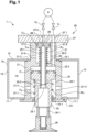
- a vacuum gripping device In reference to the figure 1 , a vacuum gripping device, generally designated 1, comprises a vacuum box 10 in which a plurality of vacuum gripping members 20 are mounted (only one of the gripping members 20 is shown).
- the box 10 comprises a lower panel 11, an upper panel 12 and side panels 13 connecting the lower panel 11 to the upper panel 12 to form a sealed enclosure 14.
- the enclosure 14 here has the shape of a rectangular parallelepiped and is intended to be connected to a vacuum generation source (not shown).
- the lower panel 11 and the upper panel 12 respectively comprise first orifices 11.1 and second orifices 12.1 for receiving the gripping members 20.
- the first orifices 11.1 and the second orifices 12.1 are circular in shape, each of the second orifices 12.1 extending here coaxially opposite one of the first orifices 11.1.
- the first orifices 11.1 here have a diameter greater than that of the second orifices 12.1.
- Each of the gripping members 20 comprises a tubular body 21 having a central axis X substantially perpendicular to the lower panel 11 and to the upper panel 12.
- the tubular body 21 is generally cylindrical in shape and externally comprises a shoulder 21.3 delimiting a first section 21.1 and a second section 21.2 of said tubular body 21.
- the first section 21.1 and the second section 21.2 are received with adjustment respectively in one of the first orifices 11.1 and in the corresponding second orifice 12.1.
- the shoulder 21.3 is in sealed contact with an internal face of the upper panel 12.
- the first section 21.1 extends inside the box 10 and comprises a first bore 22.1 opening onto a free end of the first section 21.1.
- the second section 21.2 extends outside the box 10, projecting from an external face of the upper panel 12, and comprises a second bore 22.2 opening onto a free end of the second section 21.2.
- the first bore 22.1 and the second bore 22.2 extend along the X axis and are coaxial.
- the tubular body 21 also comprises a third bore 22.3, coaxial with the first bore 22.1 and the second bore 22.2, connecting a bottom of said first bore 22.1 to a bottom of the second bore 22.2.
- the free end of the first section 21.1 receives a holding plate 23 in position of said first section 21.1 in the box 10.
- the first piston 24 defines, with the walls of the first cavity, a first chamber C 1 and a fourth chamber C 2 , both of variable volume.
- the first section 21.1 comprises suction ports 21.4 having one end opening into the second chamber C2 and an opposite end opening into the box 10.
- the suction ports 21.4 are here symmetrically and equally distributed around the axis X, in the same plane perpendicular to the axis X.
- the tubular body 20 also comprises a channel 21.5 for supplying the first chamber C1 with compressed air.
- the supply channel 21.5 extends along an axis substantially parallel to the axis X, and comprises an end opening into the first chamber C1 and an opposite end opening into a first compressed air supply orifice 27.1 formed in the plate 27.
- the first supply orifice 27.1 has an end opening into the supply channel 21.5 and an opposite end intended to be selectively connected to the compressed air source S via a first solenoid valve V1 controlled, for example, by an automaton or an electronic card (not shown).
- the first piston 24 is hollow and is provided with a tubular extension 25 which extends along the axis X from a lower face of the first piston 24 and which passes in a sealed manner through a circular opening 23.1 formed in the retaining plate 23, such that a free end section of the tubular extension 25 extends outside the box 10, projecting from an external face of the lower panel 11.
- the first piston 24 and the tubular extension 25 delimit a suction channel 25.1 extending along the axis X.
- the suction channel 25.1 has one end connected to a gripping suction cup 26 which is fixed to the free end section of the tubular extension 25 via an insert 26.1.
- the tubular extension 25 comprises suction ports 25.2 having one end opening into the suction channel 25.1 and an opposite end opening into the second chamber C 2 .
- the suction ports 25.2 are here symmetrically and equally distributed around the axis X, in a plane perpendicular to the axis X.
- the free end of the second section 21.2 receives a plate 27 for connection to a blowing device.
- the plate 27 and the second bore 22.2 together define a second cavity inside which a second piston 28 is mounted sliding along the axis X.
- the second piston 28 defines, with the walls of the second cavity, a third chamber C 3 and a fourth chamber C 4 , both of variable volume.
- the plate 27 comprises a second compressed air supply port 27.2 having one end opening into the third chamber C3 and an opposite end intended to be selectively connected to a compressed air source S via a second solenoid valve V2 controlled by the controller or the electronic card (not shown).
- the second section 21.2 comprises a vent port 21.6 having one end opening into the fourth chamber C4 and an opposite end opening outside the box 10.
- the second piston 28 is provided with a rod 29 which extends along the axis X, from a lower face of the second piston 28, and which passes through the third bore 22.3 in a sealed manner so that a free end section of the rod 29 extends into the first bore 22.1.
- the free end section of the rod 29 is received in a sealed sliding manner in the suction channel 25.1. delimited by the first piston 24 and the tubular extension 25.
- the rod 29 is hollow and delimits with the second piston 28 a compressed air conveyance channel 29.1 having one end opening into the suction channel 25.1 and an opposite end opening into the third chamber C3 via a compressed air conveyance orifice 28.1 provided on an upper face of the second piston 28.
- the conveyance orifice 28.1 has a diameter smaller than that of the second supply orifice 27.2 of the plate 27, which is itself smaller than that of the conveyance channel 29.1 of the rod 29.
- the diameter of the other of the conveyance orifice 28.1 and the channel 29.1 routing does not matter (the diameter of the routing orifice 28.1 can be equal to that of the routing channel 29.1).
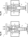
- the first piston 24 is slidably mounted between a high position called rest in which an upper face of the first piston 24 is close to the bottom of the first bore 22.1 ( figures 1 , 2A And 2D ), and a low position called gripping in which the upper face of the first piston 24 is away from the bottom of the first bore 22.1 ( Figures 2B And 2C ).
- the first piston 24 is returned to the high position by a first helical spring R 1 surrounding the tubular extension 25.
- the first spring R 1 has one end bearing against an internal face of the retaining plate 23 and the lower face of the first spring R 1 .
- the second piston 28 is slidably mounted between a high position called rest in which the upper face of the second piston 28 is in contact with a lower face of the plate 27 ( figures 1 , 2A , 2B And 2D ), and a low position called deposit in which the upper face of the second piston 28 is distant from the plate 27 ( Figure 2C ).
- the second piston 28 is returned to the high position by a second helical spring R 2 surrounding the rod 29.
- the second spring R 2 has one end bearing against the bottom of the second bore 22.2 and an opposite end bearing against the lower face of the second piston 28.
- the box 10 carrying the gripping member 20 is brought above an object P to be moved, for example via a robotic handling arm (not shown), so that the suction cup 26 of the gripping member 20 is spaced from the object P by a distance slightly less than the stroke of the first piston 24 ( Figure 2A ).
- the first solenoid valve V 1 is then brought from the closed state to the open state so that compressed air is blown into the first chamber C 1 , which has the following effect: effect of moving the first piston 24 from the high position to the low position ( Figure 2B ).
- the suction cup 26 then rests against an upper surface of the object P and is now in fluid communication with the vacuum box 10, the end section of the rod 29 no longer obstructing the suction orifices 25.2 of the tubular extension 25. It is understood that the suction cup 26 exerts a suction force on the upper surface of the object P, which causes a vacuum gripping of the object P via said suction cup 26.
- the box 10 While the first solenoid valve V 1 is maintained in the open state, the box 10 is brought via the robotic arm above the support on which the object P is to be deposited, such that the object P is spaced from the support by a distance less than a predetermined distance.
- the second solenoid valve V 2 is then brought from the closed state to the open state so that compressed air is blown into the third chamber C 3 , which has the effect of moving the second piston 28 from the high position to the low position ( Figure 2C ).
- the end section of the rod 29 then completely obstructs the suction orifices 25.2 of the tubular extension 25, and the compressed air blown into the third chamber C 3 via the second supply orifice 27.2 passes through the conveying channel 29.1 and arrives in the suction cup 26. It is then understood that the object P is blown and that it will thus fall by gravity onto the support, the suction cup 26 then no longer exerting any suction force on the object P.
- the robotic arm performs a withdrawal movement allowing the suction cup 26 to be moved away from the object P.
- the first solenoid valve V 1 is brought from the open state to the closed state so that, under the action of the first spring R 1 and the second spring R 2 , the first piston 24 and the second piston 28 move substantially simultaneously from the low position to the high position.
- the second solenoid valve V 2 is finally brought from the open state to the closed state, the gripping member 20 being again ready for a new gripping by vacuum.
- the box 10 may carry only one gripping member 20.
- the first solenoid valve V 1 and the second solenoid valve V 2 can be replaced by any device making it possible to selectively connect the first supply port 27.1 and the second supply port 23.2 to the compressed air source S.
- the first supply port 27.1 and the second supply port 27.2 of the plate 27 can be connected to separate compressed air sources.
- the second piston 28 is optional.
- the rod 29 is then fixed relative to the tubular body 20 and the object P is then removed solely by gravity when the suction cup 26 is no longer in fluid communication with the vacuum box 10, i.e. when the first solenoid valve V1 is brought from the open state to the closed state.
- a reversing valve can be mounted on the vacuum generator connected to the box 10 in order to alternate vacuum and pressure in the enclosure 14 of said box 10.
- a non-return valve may be added to the second piston 28 in order to prevent compressed air from entering the enclosure 14 of the box 10 when the second solenoid valve V 2 changes from the closed state to the open state.
Landscapes
- Engineering & Computer Science (AREA)
- Robotics (AREA)
- Mechanical Engineering (AREA)
- Manipulator (AREA)
- Load-Engaging Elements For Cranes (AREA)
Applications Claiming Priority (1)
| Application Number | Priority Date | Filing Date | Title |
|---|---|---|---|
| FR2308020A FR3151516B1 (fr) | 2023-07-25 | 2023-07-25 | Organe de préhension pour caisson à vide |
Publications (2)
| Publication Number | Publication Date |
|---|---|
| EP4497555A1 true EP4497555A1 (de) | 2025-01-29 |
| EP4497555B1 EP4497555B1 (de) | 2026-03-11 |
Family
ID=88413674
Family Applications (1)
| Application Number | Title | Priority Date | Filing Date |
|---|---|---|---|
| EP24188547.4A Active EP4497555B1 (de) | 2023-07-25 | 2024-07-15 | Greiforgan für vakuumbehälter |
Country Status (3)
| Country | Link |
|---|---|
| US (1) | US20250033226A1 (de) |
| EP (1) | EP4497555B1 (de) |
| FR (1) | FR3151516B1 (de) |
Citations (3)
| Publication number | Priority date | Publication date | Assignee | Title |
|---|---|---|---|---|
| US6431624B1 (en) * | 1999-08-21 | 2002-08-13 | Man Roland Druckmaschinen Ag | Suction gripper |
| US20090206216A1 (en) * | 2006-03-20 | 2009-08-20 | Yoshio Katsutani | Suction Device and Suction Method Using Suction Device |
| FR3043005A1 (fr) * | 2015-10-28 | 2017-05-05 | Snecma | Prehenseur pneumatique a blocage automatique, dispositif de manutention le comprenant, et procede de prehension le mettant en œuvre |
-
2023
- 2023-07-25 FR FR2308020A patent/FR3151516B1/fr active Active
-
2024
- 2024-07-15 EP EP24188547.4A patent/EP4497555B1/de active Active
- 2024-07-23 US US18/780,667 patent/US20250033226A1/en active Pending
Patent Citations (3)
| Publication number | Priority date | Publication date | Assignee | Title |
|---|---|---|---|---|
| US6431624B1 (en) * | 1999-08-21 | 2002-08-13 | Man Roland Druckmaschinen Ag | Suction gripper |
| US20090206216A1 (en) * | 2006-03-20 | 2009-08-20 | Yoshio Katsutani | Suction Device and Suction Method Using Suction Device |
| FR3043005A1 (fr) * | 2015-10-28 | 2017-05-05 | Snecma | Prehenseur pneumatique a blocage automatique, dispositif de manutention le comprenant, et procede de prehension le mettant en œuvre |
Also Published As
| Publication number | Publication date |
|---|---|
| EP4497555B1 (de) | 2026-03-11 |
| FR3151516A1 (fr) | 2025-01-31 |
| US20250033226A1 (en) | 2025-01-30 |
| FR3151516B1 (fr) | 2025-08-15 |
Similar Documents
| Publication | Publication Date | Title |
|---|---|---|
| EP3194309B1 (de) | Vorrichtung zur übertragung von beweglichen teilen | |
| EP3248738A1 (de) | Greifvorrichtung mit membran und saugnapf | |
| WO2018055257A1 (fr) | Dispositif de prehension muni d'une ventouse d'aspiration | |
| CH647189A5 (fr) | Dispositif de manipulation d'une piece cylindrique ou spherique. | |
| WO2018099615A1 (fr) | Dispositif pour manipulation d'objet sans contact | |
| EP2105393A1 (de) | Pneumatischer Greifer sowie Anordnung umfassend einer Mehrzahl solcher Greifer | |
| EP4497555B1 (de) | Greiforgan für vakuumbehälter | |
| FR3025129A1 (fr) | Dispositif de prehension | |
| FR2670148A1 (fr) | Dispositif pour conformer et maintenir des pieces minces, de grandes dimensions, a un profil theorique predetermine. | |
| EP0223779A1 (de) | Taktiler pneumatischer greifer. | |
| EP4638317A1 (de) | Vorrichtung zum lagern und verteilen von montagebauteilen mit mindestens einem drehmittel zum transferieren von montagebauteilen | |
| FR3099075A1 (fr) | Dispositif magnétique de préhension d’objet | |
| FR2786423A1 (fr) | Outil emporte-piece hydraulique | |
| EP1648610A1 (de) | Vorrichtung zum entfernen und abscheiden von tropfen mindestens einer flüssigkeit, verfahren zur verwendung der vorrichtung und servosystem für das verfahren | |
| FR3089143A1 (fr) | Dispositif de préhension à têtes magnétiques orientables | |
| EP0109405B1 (de) | Einrichtung zum greifen von gegenständen für manipulator vom robotertyp | |
| WO2019228641A1 (fr) | Dispositif pour manipulation d'objet sans contact | |
| WO1998046977A1 (fr) | Procede et dispositif de remplissage avec un milieu liquide d'une carte d'analyse | |
| FR3100004A1 (fr) | Dispositif de préhension | |
| EP3049679B1 (de) | Kartusche für eine pneumatische schaltung und sauggreifervorrichtung mit einer derartigen kartusche | |
| EP1227995B1 (de) | Vorrichtung zum greifen und bewegen eines gegenstands mit einer teilweise ebenen seite | |
| EP1232831A1 (de) | Vorrichtung zur automatischen Montage von zwei Halbkegeln auf einem Ventilschaft | |
| EP3822176B1 (de) | System zum teilchenauswurf in den weltraum | |
| WO2003090506A1 (fr) | Dispositif autonome de manipulation d'un composant electronique par effet magnetique | |
| FR3085878A1 (fr) | Outil de prehension electromagnetique polyvalent et deformable a double membrane |
Legal Events
| Date | Code | Title | Description |
|---|---|---|---|
| PUAI | Public reference made under article 153(3) epc to a published international application that has entered the european phase |
Free format text: ORIGINAL CODE: 0009012 |
|
| STAA | Information on the status of an ep patent application or granted ep patent |
Free format text: STATUS: THE APPLICATION HAS BEEN PUBLISHED |
|
| AK | Designated contracting states |
Kind code of ref document: A1 Designated state(s): AL AT BE BG CH CY CZ DE DK EE ES FI FR GB GR HR HU IE IS IT LI LT LU LV MC ME MK MT NL NO PL PT RO RS SE SI SK SM TR |
|
| STAA | Information on the status of an ep patent application or granted ep patent |
Free format text: STATUS: REQUEST FOR EXAMINATION WAS MADE |
|
| 17P | Request for examination filed |
Effective date: 20250527 |
|
| GRAP | Despatch of communication of intention to grant a patent |
Free format text: ORIGINAL CODE: EPIDOSNIGR1 |
|
| STAA | Information on the status of an ep patent application or granted ep patent |
Free format text: STATUS: GRANT OF PATENT IS INTENDED |
|
| RIC1 | Information provided on ipc code assigned before grant |
Ipc: B25J 15/06 20060101AFI20250915BHEP |
|
| INTG | Intention to grant announced |
Effective date: 20251021 |
|
| GRAS | Grant fee paid |
Free format text: ORIGINAL CODE: EPIDOSNIGR3 |
|
| GRAA | (expected) grant |
Free format text: ORIGINAL CODE: 0009210 |
|
| STAA | Information on the status of an ep patent application or granted ep patent |
Free format text: STATUS: THE PATENT HAS BEEN GRANTED |
|
| AK | Designated contracting states |
Kind code of ref document: B1 Designated state(s): AL AT BE BG CH CY CZ DE DK EE ES FI FR GB GR HR HU IE IS IT LI LT LU LV MC ME MK MT NL NO PL PT RO RS SE SI SK SM TR |
|
| REG | Reference to a national code |
Ref country code: CH Ref legal event code: F10 Free format text: ST27 STATUS EVENT CODE: U-0-0-F10-F00 (AS PROVIDED BY THE NATIONAL OFFICE) Effective date: 20260311 Ref country code: GB Ref legal event code: FG4D Free format text: NOT ENGLISH |
|
| REG | Reference to a national code |
Ref country code: DE Ref legal event code: R096 Ref document number: 602024003103 Country of ref document: DE |
|
| REG | Reference to a national code |
Ref country code: IE Ref legal event code: FG4D Free format text: LANGUAGE OF EP DOCUMENT: FRENCH |