EP4497561A1 - Vorrichtung zum recycling von reifen - Google Patents
Vorrichtung zum recycling von reifen Download PDFInfo
- Publication number
- EP4497561A1 EP4497561A1 EP24151835.6A EP24151835A EP4497561A1 EP 4497561 A1 EP4497561 A1 EP 4497561A1 EP 24151835 A EP24151835 A EP 24151835A EP 4497561 A1 EP4497561 A1 EP 4497561A1
- Authority
- EP
- European Patent Office
- Prior art keywords
- nozzle
- nozzle assembly
- tyre
- rubber
- rollers
- Prior art date
- Legal status (The legal status is an assumption and is not a legal conclusion. Google has not performed a legal analysis and makes no representation as to the accuracy of the status listed.)
- Pending
Links
Images


Classifications
-
- B—PERFORMING OPERATIONS; TRANSPORTING
- B29—WORKING OF PLASTICS; WORKING OF SUBSTANCES IN A PLASTIC STATE IN GENERAL
- B29B—PREPARATION OR PRETREATMENT OF THE MATERIAL TO BE SHAPED; MAKING GRANULES OR PREFORMS; RECOVERY OF PLASTICS OR OTHER CONSTITUENTS OF WASTE MATERIAL CONTAINING PLASTICS
- B29B17/00—Recovery of plastics or other constituents of waste material containing plastics
- B29B17/04—Disintegrating plastics, e.g. by milling
- B29B17/0404—Disintegrating plastics, e.g. by milling to powder
-
- B—PERFORMING OPERATIONS; TRANSPORTING
- B09—DISPOSAL OF SOLID WASTE; RECLAMATION OF CONTAMINATED SOIL
- B09B—DISPOSAL OF SOLID WASTE NOT OTHERWISE PROVIDED FOR
- B09B3/00—Destroying solid waste or transforming solid waste into something useful or harmless
- B09B3/30—Destroying solid waste or transforming solid waste into something useful or harmless involving mechanical treatment
- B09B3/35—Shredding, crushing or cutting
-
- B—PERFORMING OPERATIONS; TRANSPORTING
- B29—WORKING OF PLASTICS; WORKING OF SUBSTANCES IN A PLASTIC STATE IN GENERAL
- B29B—PREPARATION OR PRETREATMENT OF THE MATERIAL TO BE SHAPED; MAKING GRANULES OR PREFORMS; RECOVERY OF PLASTICS OR OTHER CONSTITUENTS OF WASTE MATERIAL CONTAINING PLASTICS
- B29B17/00—Recovery of plastics or other constituents of waste material containing plastics
- B29B17/02—Separating plastics from other materials
-
- B—PERFORMING OPERATIONS; TRANSPORTING
- B02—CRUSHING, PULVERISING, OR DISINTEGRATING; PREPARATORY TREATMENT OF GRAIN FOR MILLING
- B02C—CRUSHING, PULVERISING, OR DISINTEGRATING IN GENERAL; MILLING GRAIN
- B02C19/00—Other disintegrating devices or methods
- B02C19/0056—Other disintegrating devices or methods specially adapted for specific materials not otherwise provided for
-
- B—PERFORMING OPERATIONS; TRANSPORTING
- B26—HAND CUTTING TOOLS; CUTTING; SEVERING
- B26F—PERFORATING; PUNCHING; CUTTING-OUT; STAMPING-OUT; SEVERING BY MEANS OTHER THAN CUTTING
- B26F3/00—Severing by means other than cutting; Apparatus therefor
- B26F3/004—Severing by means other than cutting; Apparatus therefor by means of a fluid jet
-
- B—PERFORMING OPERATIONS; TRANSPORTING
- B09—DISPOSAL OF SOLID WASTE; RECLAMATION OF CONTAMINATED SOIL
- B09B—DISPOSAL OF SOLID WASTE NOT OTHERWISE PROVIDED FOR
- B09B2101/00—Type of solid waste
- B09B2101/80—Rubber waste, e.g. scrap tyres
-
- B—PERFORMING OPERATIONS; TRANSPORTING
- B29—WORKING OF PLASTICS; WORKING OF SUBSTANCES IN A PLASTIC STATE IN GENERAL
- B29B—PREPARATION OR PRETREATMENT OF THE MATERIAL TO BE SHAPED; MAKING GRANULES OR PREFORMS; RECOVERY OF PLASTICS OR OTHER CONSTITUENTS OF WASTE MATERIAL CONTAINING PLASTICS
- B29B17/00—Recovery of plastics or other constituents of waste material containing plastics
- B29B2017/0094—Mobile recycling devices, e.g. devices installed in truck trailers
-
- B—PERFORMING OPERATIONS; TRANSPORTING
- B29—WORKING OF PLASTICS; WORKING OF SUBSTANCES IN A PLASTIC STATE IN GENERAL
- B29B—PREPARATION OR PRETREATMENT OF THE MATERIAL TO BE SHAPED; MAKING GRANULES OR PREFORMS; RECOVERY OF PLASTICS OR OTHER CONSTITUENTS OF WASTE MATERIAL CONTAINING PLASTICS
- B29B17/00—Recovery of plastics or other constituents of waste material containing plastics
- B29B17/04—Disintegrating plastics, e.g. by milling
- B29B2017/0424—Specific disintegrating techniques; devices therefor
- B29B2017/0428—Jets of high pressure fluid
-
- B—PERFORMING OPERATIONS; TRANSPORTING
- B29—WORKING OF PLASTICS; WORKING OF SUBSTANCES IN A PLASTIC STATE IN GENERAL
- B29L—INDEXING SCHEME ASSOCIATED WITH SUBCLASS B29C, RELATING TO PARTICULAR ARTICLES
- B29L2030/00—Pneumatic or solid tyres or parts thereof
Definitions
- the present invention relates to a recycling apparatus forming part of a method of recycling of car tyres, and separates the rubber, fibrous, and metal components of a tyre. More especially, the invention relates to a tyre recycling unit that allows the processing of tyres and the separation of rubber crumb by particle size.
- the applicant has developed a tyre recycling technology that uses ultra-high-pressure water (UHPW) to remove rubber from the steel latus of vehicle tyres.
- UHPW ultra-high-pressure water
- the water jet breaks down the rubber components and fibrous material into pieces, which are readily separated from the metal components.
- This operation uses water at a pressure of around 40,000 PSI to process a vehicle tyre in approximately 30 seconds.
- An important aspect of rubber recycling is the yield and consistency of separated materials, particularly with respect to differing rubber grades and rubber crumb particle sizes.
- tyres are formed of different grades of rubber which are used for different parts of the tyre. For example, the highest quality of rubber is used in the tread portion to provide grip. To separate grades of rubber, tyres are cut into respective segments prior to processing.
- Cut tyre portions are not of equal dimension with respect to width, length or general shape.
- Known processes with fixed positioned water jets therefore must accommodate an area great enough to ensure the entire tyre portion is pulverized.
- inefficiencies in the area covered and loss of rubber crumb yield can occur about the external perimeters of a tyre portion.
- Rubber crumb particle size is dependent on several factors, such as water pressure, location of water jets, contact time between tyre portions and water jet and dissipation of kinetic energy transferred from said water jet with respect to the tyre portion (oscillation of the tyre portion).
- the present invention seeks to provide a tyre recycling unit that can efficiently separate tyre component materials. Specifically, the present invention provides an apparatus and method of producing consistent high yield batches of rubber crumb, with respect to particle size and rubber grade.
- the present further provides a mobile tyre recycling unit that can be transported on constructed on site.
- apparatus for removing rubber from tyres comprising a main housing in which is supported a water jet nozzle assembly, a guide mechanism and a collection chamber, the guiding mechanism providing a means for directing at least a section of flattened tyre part under the nozzle assembly in a manner that is substantially perpendicular to the nozzle assembly, the nozzle assembly including at least one nozzle to direct high-pressure water onto the tyre part, to thereby remove the rubber, wherein the rubber is captured and delivered into the collection chamber.
- the housing is constructed from upper and lower box sections, the nozzle assembly being supported above the guide mechanism in the top section and an entrance to the collection chamber being located directly under the nozzle assembly in the lower section.
- the guide mechanism includes an array of rollers.
- the roller array consists of a plurality of rollers of a first diameter, each divided by a roller of a second diameter, smaller than the first diameter.
- the roller array is supported by roller plates, each connected to a respective side arched plate.
- At least one dividing rod extends between the side arched plates above the roller array.
- the rollers are rotated by a drive wheel located under the guide mechanism within the housing.
- rollers and roller plates are separated laterally to provide a gap in which the nozzle assembly us supported.
- the nozzle assembly includes a nozzle support plate having a lengthwise slot, and a nozzle carrier which extends through the slot.
- the nozzle carrier is secured to a slide block located under the support plate to allowing slidable movement of the nozzle carrier within the slot.
- the slide block is driven by a servometer attached to the housing.
- the bottom end of the nozzle carrier has at least one nozzle to direct high-pressure water on to a tyre part guided through the guide mechanism under the nozzle carrier.
- a shoe is supported on the underside of the slide block to impart a compressive force to the tyre part as it is guided underneath the nozzle assembly.
- the shoe has a central aperture through which the water is directed from the nozzle.
- multidirectional rollers are provided on the underside of the shoe.
- the collection container is a hopper.
- the apparatus further comprises an exit chute or funnel to remove processed tyre parts from then housing.
- a method of processing tyres to remove and collect rubber comprising the steps of: separating sidewalls from the tyre; cutting the resulting tyre part to allow it to be laid flat; feeding the tyre part into the guide mechanism of the apparatus described; controlling movement of the nozzle assembly and/or speed of the drive wheel to pulverise the rubber in a defined manner; collecting the rubber in the collection chamber; and collecting the remaining tyre part with the rubber removed.
- the method may also include the step of transporting the rubber to an industrial sieve to separate the rubber into various size profiles.
- the present invention describes a tyre processing unit which forms the main part of a tyre recycling process.
- feed material is created though a preliminary but separate process. This process involves preparing the raw material (in the present description being tyres) by separating (cutting) the sidewalls from the tyre and providing a single cut through the tread so that the tyre parts can be laid flat. Once flat, the tyre parts can be fed into the processing unit.
- the tyre parts are then processed in the processing unit in a way that will be later described; during which time the rubber is pulverised and separated from the steel mesh.
- the rubber-free, clean, steel is directed away from the processing unit to a collection container, by means of a chute, funnel or other delivery system.
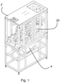
- Figure 1 shows the processing unit with the outer panels removed for the purpose of describing the internal features.
- the unit is a stand-alone piece of machinery allowing for it to be fairly portable and suitable for transportation to a desired location.
- the unit comprises a housing 2 of an outer framework consisting of connected horizontal and vertical struts, which houses a guide mechanism to feed tyres into and through the processing unit, and a hopper 4 to collect pulverised rubber produced by the process.
- the framework is formed generally with upper and lower box sections, made from stainless steel or other suitable material suitable for outside industrial environments. Panelling (not shown) is provided around the top section to protect the working components from the outside environment.
- the guide mechanism and hopper 4 are more clearly shown in figure 2 . Both are held above the ground generally centrally within the housing 2.
- a jet nozzle assembly 6 is held within the housing 2 above the guide mechanism to direct an ultra-high-pressure jet of water downwardly onto the tyre or tyre part being fed through the guiding mechanism, in order to pulverize the rubber on the tyre.
- the guide mechanism includes an array of rollers 8 supported by roller plates 10 each connected to respective side arch plates 12.
- the roller array 8 consists of a plurality of rollers 8A typically of a diameter of 50mm, each divided by rollers 8B of smaller diameter, typically 20mm. This minimizes the risk of the tyre part being caught in any gap between the rollers 8 causing a blockage in the guiding mechanism.
- Each side arch plate12 is separated from raised sides of the roller plate 10 by a spacer 14.
- Dividing rods 16 are connected to, and extend between, the side plates 12 above the rollers 8 at a sufficient height so not to hinder tyre parts being fed through the guiding mechanism underneath.
- the rods 16 prevent the tyres lifting off the rollers 8 and getting caught within the guide mechanism causing a blockage.
- the dividing rods 16 are extendible using extension members 18 to allow variable width to accommodate wider tyre parts being fed through guiding mechanism.
- Spacers 20 are provided between the ends of rollers 8 and the roller plates 10 to ensure that the rollers 8 remain free to rotate.
- the rollers 8 are rotated by a drive wheel 22 made from stainless steel or other appropriate material, driven by a drive motor 23 and gearbox.
- the width of the drive wheel 22 provides a surface to support and hold the tyre parts in place whilst they move through the guiding mechanism.
- the surface of the drive wheel 22 may be flexible.
- roller plates 10 and rollers 8 are divided laterally into curved sections 10A, 10B, forming together the overall arched structure.
- the sections 10A, 10B are separated to provide a gap in which the jet nozzle assembly 6 can locate.
- the side plates 12 are not separated and extend across the gap and provide side walls 24 between which a nozzle support plate 26 is supported.
- the nozzle plate 26 is generally flat and has a through slot 28 extending lengthwise in a side part of the plate 26 (see figure 6 ).
- the nozzle assembly 6 is held on a nozzle carrier 30 which extends downwardly through the slot 28.
- the bottom end of the carrier 30 is secured to a slide block 34, under the support plate 26.
- the slide block 34 is linked to a servomotor 36 via a drive rod 38 to move the nozzle assembly 6 within and along the slot 28 in a perpendicular manner across the width of the tyre part below to ensure the complete granulation, crumbing or pulverization of all the rubber associated with the tyre parts.
- the servomotor 36 allows adjustability of speed and the coverage (distance) of the width of the tyre part.
- the servometer 36 is interfaced with programmable logic controller with a human-machine interface for operation.
- a frame extends downwardly from the slide block 34, at the end of which is supported a slipper shoe 40 orientated parallel to the slide block 34 and that imparts a uniform compressing force against the tyre parts to retain them flat against the drive wheel 22.
- Multi-directional rollers 42 are located on the undersurface of the shoe 40, which engage the tyre parts, to allow the tyre parts to pass under the nozzles 32 perpendicular to the nozzle carrier 28.
- the shoe 40 has a central aperture 44 of sufficient diameter to accommodate the nozzle head above.
- the shoe 40, slide block 34 and support plate 26 are configured to have a low coefficient of friction at their interfaces with the tyre portion.
- the low coefficient of friction prevents sticking or binding of the tyre parts to the apparatus.
- the shoe 40 and nozzles 32 can traverse the tyre parts at a variable speed which allows control of contact time between the water jet and tyre portion, therefore controlling the particle size of the resultant rubber crumb.
- the nozzle carrier head containing the nozzles 32 moves back and forth in a perpendicular manner across the width of the tyre part to ensure the complete granulation, crumbing or pulverization of all the rubber associated with the tyre parts.
- the system is designed to process tyres in high volumes and requires the sidewalls of the tyre to be removed prior to use. Tyres are cut into portions to separate differing rubber grades of the tyre and so that the tyre portions can be laid flat and fed into the system.
- the cut tyre portion is fed in one end of the machine manually, where it engages with the drive wheel 22 to be manoeuvred towards and under the nozzles 32.
- the stripped tyre/wire mesh is then fed out of the unit through an outfeed exit chute or funnel.
- the rubber product is collected in a hopper 4 in a bottom part of the housing 2 directly under the nozzle assembly 6. Thereafter the rubber product is and pumped, with water, to an industrial sieve that separates the rubber crumb into different particle sizes for recycling.
- the rate and removal of rubber and/or the size distribution of rubber crumb, granulate or powder can be selected or optimised in a number of ways.
- the speed of the drive wheel 22 will also impact how much material is removed from the tyre pieces; a slower speed removing more material and vice versa.
- the rate of removal of rubber will also be impacted by varying the distance between the jet nozzles 32 and the surface of the tyre part, varying the the orifice size, angle and quantity of nozzles, or varying the pressure and/or flow rate of the ultra-high pressure water jet.
Landscapes
- Engineering & Computer Science (AREA)
- Environmental & Geological Engineering (AREA)
- Mechanical Engineering (AREA)
- Food Science & Technology (AREA)
- Life Sciences & Earth Sciences (AREA)
- Forests & Forestry (AREA)
- Separation, Recovery Or Treatment Of Waste Materials Containing Plastics (AREA)
- Processing Of Solid Wastes (AREA)
Applications Claiming Priority (1)
| Application Number | Priority Date | Filing Date | Title |
|---|---|---|---|
| GBGB2311557.9A GB202311557D0 (en) | 2023-07-27 | 2023-07-27 | Method and apparatus for separating rubber components and metal components |
Publications (1)
| Publication Number | Publication Date |
|---|---|
| EP4497561A1 true EP4497561A1 (de) | 2025-01-29 |
Family
ID=87929897
Family Applications (1)
| Application Number | Title | Priority Date | Filing Date |
|---|---|---|---|
| EP24151835.6A Pending EP4497561A1 (de) | 2023-07-27 | 2024-01-15 | Vorrichtung zum recycling von reifen |
Country Status (4)
| Country | Link |
|---|---|
| US (1) | US20250033100A1 (de) |
| EP (1) | EP4497561A1 (de) |
| CA (1) | CA3226157A1 (de) |
| GB (2) | GB202311557D0 (de) |
Citations (6)
| Publication number | Priority date | Publication date | Assignee | Title |
|---|---|---|---|---|
| EP0591266B1 (de) * | 1991-06-13 | 1998-09-02 | Southern Rubber Pty Ltd | Verfahren zum wiedergewinnen von gummi aus altreifen |
| DE102016224866A1 (de) * | 2016-12-13 | 2018-06-14 | Koenig & Bauer Ag | Vorrichtung und Verfahren zum Abtragen eines Materials von der Lauffläche eines Reifenstreifens |
| DE102016224867A1 (de) * | 2016-12-13 | 2018-06-14 | Koenig & Bauer Ag | Vorrichtung und Verfahren zum Abtragen eines Materials von der Lauffläche eines Reifenstreifens |
| CH714352A1 (fr) * | 2017-11-17 | 2019-05-31 | Tyre Recycling Solutions Sa | Machine pour le recyclage des pneus. |
| WO2021019357A1 (fr) * | 2019-07-31 | 2021-02-04 | Tyre Recycling Solutions Sa | Machine pour le recyclage des pneus |
| GB2607860A (en) | 2021-04-15 | 2022-12-21 | Exo Cubic Solutions Ltd | Tyre pulverisation process |
Family Cites Families (4)
| Publication number | Priority date | Publication date | Assignee | Title |
|---|---|---|---|---|
| US4600106A (en) * | 1983-11-17 | 1986-07-15 | Maurice Minardi | Separation of molded parts from connectors |
| GB2504084A (en) * | 2012-07-16 | 2014-01-22 | Symphony Recycling Technologies Ltd | Method and apparatus for separating rubber and metal components |
| HRP20210988T1 (hr) * | 2017-02-14 | 2021-09-17 | PNEUS JET RECYCLING Srl | Uređaj za razaranje guma |
| CN206870203U (zh) * | 2017-03-02 | 2018-01-12 | 高玉海 | 轮胎回收处理设备及用于胎肩的水射流粉碎装置 |
-
2023
- 2023-07-27 GB GBGB2311557.9A patent/GB202311557D0/en not_active Ceased
-
2024
- 2024-01-15 CA CA3226157A patent/CA3226157A1/en active Pending
- 2024-01-15 EP EP24151835.6A patent/EP4497561A1/de active Pending
- 2024-01-16 US US18/414,124 patent/US20250033100A1/en active Pending
- 2024-06-19 GB GB2408805.6A patent/GB2633171A/en active Pending
Patent Citations (6)
| Publication number | Priority date | Publication date | Assignee | Title |
|---|---|---|---|---|
| EP0591266B1 (de) * | 1991-06-13 | 1998-09-02 | Southern Rubber Pty Ltd | Verfahren zum wiedergewinnen von gummi aus altreifen |
| DE102016224866A1 (de) * | 2016-12-13 | 2018-06-14 | Koenig & Bauer Ag | Vorrichtung und Verfahren zum Abtragen eines Materials von der Lauffläche eines Reifenstreifens |
| DE102016224867A1 (de) * | 2016-12-13 | 2018-06-14 | Koenig & Bauer Ag | Vorrichtung und Verfahren zum Abtragen eines Materials von der Lauffläche eines Reifenstreifens |
| CH714352A1 (fr) * | 2017-11-17 | 2019-05-31 | Tyre Recycling Solutions Sa | Machine pour le recyclage des pneus. |
| WO2021019357A1 (fr) * | 2019-07-31 | 2021-02-04 | Tyre Recycling Solutions Sa | Machine pour le recyclage des pneus |
| GB2607860A (en) | 2021-04-15 | 2022-12-21 | Exo Cubic Solutions Ltd | Tyre pulverisation process |
Also Published As
| Publication number | Publication date |
|---|---|
| GB202408805D0 (en) | 2024-07-31 |
| US20250033100A1 (en) | 2025-01-30 |
| GB2633171A (en) | 2025-03-05 |
| GB202311557D0 (en) | 2023-09-13 |
| CA3226157A1 (en) | 2025-06-13 |
Similar Documents
| Publication | Publication Date | Title |
|---|---|---|
| US5482215A (en) | Method of reclaiming rubber from vehicle tires | |
| EP0515321B1 (de) | Einrichtung zum Zerkleinern von gebrauchten Fahrzeugreifen und dergleichen sowie Trennen von Metallteilen von Nichtmetallteilen von diesem zerkleinerten Material | |
| KR0167788B1 (ko) | 무기섬유 매트 제조방법 및 장치 | |
| JP2007511365A (ja) | クラム及びパウダーゴムの製造方法及び製造装置 | |
| US20120035282A1 (en) | Process for the continuous cycle recycling of materials contained in products coupled to other materials by disintegration through water jets at high/ultrahigh pressure and products obtained in this way | |
| US8317115B2 (en) | Micro-erosion recovery system for tire materials | |
| EP4497561A1 (de) | Vorrichtung zum recycling von reifen | |
| CN114523602A (zh) | 一种模具钢边角料的回收再利用系统及方法 | |
| CN104875297B (zh) | 利用废旧轮胎制取精细胶粉系统 | |
| KR102694280B1 (ko) | 타이어 재활용 기계 | |
| CN213102415U (zh) | 一种用于道路维修的石子快速粉碎设备 | |
| CN118417295B (zh) | 一种煤矸石固废处理设备及处理方法 | |
| EP2703096A2 (de) | Prozesslinie zur Verarbeitung vom Autoschrott | |
| CN210700420U (zh) | 球磨机上料装置 | |
| GB2607860A (en) | Tyre pulverisation process | |
| CN217989439U (zh) | 粉料收集装置以及研磨系统 | |
| CN117861551B (zh) | 一种生物质能燃料成型装置及其使用方法 | |
| CN211334163U (zh) | 一种塑料制品生产加工用废料回收装置 | |
| CN117983106A (zh) | 一种多级沙料提升水泥质量的装置及方法 | |
| BR112022001663B1 (pt) | Máquina e processo de reciclagem de pneus pela recuperação de borracha das bandas de rodagem de pneus por jato de água | |
| CN119116217A (zh) | 一种利用废旧轮胎加工成橡胶粉的多级粉碎装置及粉碎方法 | |
| EP2000274A2 (de) | Bearbeitungsstrasse für schleifmaterial, insbesondere altreifen | |
| ITFI970273A1 (it) | Impianto per la frantumazione di pneumatici usati,il recupero di materiale sintetico e la formazione di prodotti con il materiale | |
| CN107149967A (zh) | 高效耐用钢丝轮胎块破碎机 |
Legal Events
| Date | Code | Title | Description |
|---|---|---|---|
| PUAI | Public reference made under article 153(3) epc to a published international application that has entered the european phase |
Free format text: ORIGINAL CODE: 0009012 |
|
| STAA | Information on the status of an ep patent application or granted ep patent |
Free format text: STATUS: THE APPLICATION HAS BEEN PUBLISHED |
|
| AK | Designated contracting states |
Kind code of ref document: A1 Designated state(s): AL AT BE BG CH CY CZ DE DK EE ES FI FR GB GR HR HU IE IS IT LI LT LU LV MC ME MK MT NL NO PL PT RO RS SE SI SK SM TR |
|
| STAA | Information on the status of an ep patent application or granted ep patent |
Free format text: STATUS: REQUEST FOR EXAMINATION WAS MADE |
|
| 17P | Request for examination filed |
Effective date: 20250305 |
|
| RAP3 | Party data changed (applicant data changed or rights of an application transferred) |
Owner name: RETYRE-TECH LIMITED |