EP4497571A1 - Modulare maschine zur herstellung durch addition, subtraktion oder materialumwandlung - Google Patents
Modulare maschine zur herstellung durch addition, subtraktion oder materialumwandlung Download PDFInfo
- Publication number
- EP4497571A1 EP4497571A1 EP24191112.2A EP24191112A EP4497571A1 EP 4497571 A1 EP4497571 A1 EP 4497571A1 EP 24191112 A EP24191112 A EP 24191112A EP 4497571 A1 EP4497571 A1 EP 4497571A1
- Authority
- EP
- European Patent Office
- Prior art keywords
- module
- manufacturing
- docking station
- head
- filament
- Prior art date
- Legal status (The legal status is an assumption and is not a legal conclusion. Google has not performed a legal analysis and makes no representation as to the accuracy of the status listed.)
- Withdrawn
Links
Images




Classifications
-
- B—PERFORMING OPERATIONS; TRANSPORTING
- B29—WORKING OF PLASTICS; WORKING OF SUBSTANCES IN A PLASTIC STATE IN GENERAL
- B29C—SHAPING OR JOINING OF PLASTICS; SHAPING OF MATERIAL IN A PLASTIC STATE, NOT OTHERWISE PROVIDED FOR; AFTER-TREATMENT OF THE SHAPED PRODUCTS, e.g. REPAIRING
- B29C64/00—Additive manufacturing, i.e. manufacturing of three-dimensional [3D] objects by additive deposition, additive agglomeration or additive layering, e.g. by 3D printing, stereolithography or selective laser sintering
- B29C64/10—Processes of additive manufacturing
- B29C64/106—Processes of additive manufacturing using only liquids or viscous materials, e.g. depositing a continuous bead of viscous material
- B29C64/118—Processes of additive manufacturing using only liquids or viscous materials, e.g. depositing a continuous bead of viscous material using filamentary material being melted, e.g. fused deposition modelling [FDM]
-
- B—PERFORMING OPERATIONS; TRANSPORTING
- B29—WORKING OF PLASTICS; WORKING OF SUBSTANCES IN A PLASTIC STATE IN GENERAL
- B29C—SHAPING OR JOINING OF PLASTICS; SHAPING OF MATERIAL IN A PLASTIC STATE, NOT OTHERWISE PROVIDED FOR; AFTER-TREATMENT OF THE SHAPED PRODUCTS, e.g. REPAIRING
- B29C64/00—Additive manufacturing, i.e. manufacturing of three-dimensional [3D] objects by additive deposition, additive agglomeration or additive layering, e.g. by 3D printing, stereolithography or selective laser sintering
- B29C64/30—Auxiliary operations or equipment
- B29C64/379—Handling of additively manufactured objects, e.g. using robots
-
- B—PERFORMING OPERATIONS; TRANSPORTING
- B29—WORKING OF PLASTICS; WORKING OF SUBSTANCES IN A PLASTIC STATE IN GENERAL
- B29C—SHAPING OR JOINING OF PLASTICS; SHAPING OF MATERIAL IN A PLASTIC STATE, NOT OTHERWISE PROVIDED FOR; AFTER-TREATMENT OF THE SHAPED PRODUCTS, e.g. REPAIRING
- B29C64/00—Additive manufacturing, i.e. manufacturing of three-dimensional [3D] objects by additive deposition, additive agglomeration or additive layering, e.g. by 3D printing, stereolithography or selective laser sintering
- B29C64/30—Auxiliary operations or equipment
- B29C64/386—Data acquisition or data processing for additive manufacturing
- B29C64/393—Data acquisition or data processing for additive manufacturing for controlling or regulating additive manufacturing processes
-
- B—PERFORMING OPERATIONS; TRANSPORTING
- B33—ADDITIVE MANUFACTURING TECHNOLOGY
- B33Y—ADDITIVE MANUFACTURING, i.e. MANUFACTURING OF THREE-DIMENSIONAL [3D] OBJECTS BY ADDITIVE DEPOSITION, ADDITIVE AGGLOMERATION OR ADDITIVE LAYERING, e.g. BY 3D PRINTING, STEREOLITHOGRAPHY OR SELECTIVE LASER SINTERING
- B33Y30/00—Apparatus for additive manufacturing; Details thereof or accessories therefor
-
- B—PERFORMING OPERATIONS; TRANSPORTING
- B33—ADDITIVE MANUFACTURING TECHNOLOGY
- B33Y—ADDITIVE MANUFACTURING, i.e. MANUFACTURING OF THREE-DIMENSIONAL [3D] OBJECTS BY ADDITIVE DEPOSITION, ADDITIVE AGGLOMERATION OR ADDITIVE LAYERING, e.g. BY 3D PRINTING, STEREOLITHOGRAPHY OR SELECTIVE LASER SINTERING
- B33Y40/00—Auxiliary operations or equipment, e.g. for material handling
-
- B—PERFORMING OPERATIONS; TRANSPORTING
- B22—CASTING; POWDER METALLURGY
- B22F—WORKING METALLIC POWDER; MANUFACTURE OF ARTICLES FROM METALLIC POWDER; MAKING METALLIC POWDER; APPARATUS OR DEVICES SPECIALLY ADAPTED FOR METALLIC POWDER
- B22F12/00—Apparatus or devices specially adapted for additive manufacturing; Auxiliary means for additive manufacturing; Combinations of additive manufacturing apparatus or devices with other processing apparatus or devices
- B22F12/80—Plants, production lines or modules
- B22F12/82—Combination of additive manufacturing apparatus or devices with other processing apparatus or devices
- B22F12/86—Serial processing with multiple devices grouped
Definitions
- the present disclosure relates to a modular machine for manufacturing by addition, subtraction or transformation of material, which may in particular comprise one or more three-dimensional printing modules by fused wire deposition.
- a 3D printing machine by fused deposition modeling conventionally comprises a frame comprising a location for a spool of filament to be deposited, a support plate for an object to be manufactured, and a heating nozzle movable relative to the support plate, into which filament unwound from the spool is fed.
- the heating nozzle makes it possible to deposit the molten filament in successive layers to form the object to be manufactured.
- a controller makes it possible to control the movement of the nozzle, also the heating, the filament drive means, etc.
- a disadvantage of this type of machine is that it generally includes one or two reels and associated nozzles, which limits the diversity of possible parts, since it may be necessary to change the reel during production to be able to print parts of different colors, or even to change a nozzle associated with a reel to be able to print according to a desired printing width, since this printing width is determined by the nozzle which generally has a section of constant diameter.
- This disclosure improves the situation.
- an aim of the present disclosure is to propose a modular machine for manufacturing objects, offering a diversity of tools for simpler and faster manufacturing of objects, possibly complex.
- Another object of the present disclosure is to provide a machine which may include one or more fused deposition modeling printing modules.
- Another aim of the present disclosure is to provide a machine whose module configuration can be changed simply.
- each docking station of a manufacturing module comprises a memory storing configuration information of the manufacturing module, and the secondary controller is configured to transmit said configuration information to the primary controller during an initialization phase of the manufacturing module.
- each docking station includes a removable build head presence sensor, and the secondary controller is configured to communicate a presence or absence status of the removable build head to the primary controller.
- the moving device comprises a carriage movable in a plane parallel to the support plate, the carriage comprising mechanical and electrical connection means with a manufacturing head, a motor, and a dog driven by the motor.
- the machine comprises two alignments of locations of the manufacturing modules, arranged parallel to each other, on either side of the support plate of the object to be manufactured.
- the device for moving a manufacturing head comprises an arm movable in translation in a direction parallel to the alignments of the locations of the modules, and a carriage movable in translation in the arm, in a direction perpendicular to the direction of movement of the arm, the carriage comprising means of removable gripping of a module manufacturing head, arranged on either side of the carriage in its direction of movement.
- the device for moving a manufacturing head comprises a carriage movable in a plane parallel to the support plate, and at least one belt for moving the movable carriage defining a closed contour, and the locations for the manufacturing modules are located inside the contour defined by the belt.
- the moving device comprises two superimposed moving belts moving in opposite directions.
- the machine includes a module slot support part including the mechanical and electrical connectors of a plurality of module slots, an electronic board on which the electrical connectors are mounted, and a housing for the passage of each belt.
- the machine includes at least one fused deposition modeling module, the docking station of which is configured to supply filament to the head, and the head includes a filament heater, and a deposition nozzle.
- the head of the fused deposition modeling module further comprises a drive mechanism adapted to be driven by the carriage motor via a dog clutch, when the carriage is connected to the head.
- the frame includes a spool holder and a wire collection bin disposed beneath each manufacturing module location.
- the secondary controller of the docking station of the fused deposition modeling module is configured to transmit to the primary controller information relating to a length of filament consumed and/or an alert relating to an event such as a breakage or absence of filament.
- the main controller is configured to control the implementation of a manufacturing sequence involving the operation, in succession, of a first manufacturing module and the fused deposition modeling module, and the docking station of the fused deposition modeling module is further configured, upon receipt of instructions from the main controller, to preheat and preload the print head with filament, during operation of the first manufacturing module.
- the manufacturing module comprising a docking station and a manufacturing head removable with respect to the docking station, wherein the docking station comprises a controller, and comprises connection means, for example electrical and mechanical connectors, adapted to allow its mounting on the frame of the machine in a removable manner.
- the docking station and the manufacturing head comprise controlled electromagnetic coupling means, and electrical connection means.
- the docking station includes a motor and a coupling member with an output shaft of the motor
- the manufacturing head includes movable mechanical parts and a coupling member adapted to cooperate with the coupling member of the docking station and to drive the movable mechanical parts into motion once the coupling is achieved.
- the module is a fused deposition modeling printing module, wherein the docking station is configured to supply filament to the head, and the head includes a filament heater and a deposition nozzle.
- the docking station further comprises at least one sensor adapted to detect a breakage or absence of filament, and/or to measure a length of filament consumed.
- the proposed machine comprises one or more manufacturing modules, each module comprising a docking station removably mounted on a location dedicated for this purpose on the machine frame.
- the location and the docking station being provided with electrical connectors, and the docking station comprising its own controller, the mounting of a module on the frame makes it possible to put the controller of the docking station in communication with the main controller of the machine. Thanks to this communication, the main controller can know the configuration of the machine (number of modules, function of each module, parameterization associated with each module) and manage the operation of the machine accordingly.
- Each docking station may also include a presence sensor for the associated tool head, and communicate the present or absent status of the tool head to the main controller.
- Each docking station may also include additional functionality that may depend on the nature of the manufacturing tool formed by the module.
- a docking station of a fused deposition modeling module may also include functionality for priming and monitoring the presence of filament, and for measuring the amount of filament used.
- the mechanical configuration of the machine is also adapted to its modular nature.
- the locations for the modules are aligned according to two alignments arranged on either side of the support plate.
- the device for moving a module head comprises a carriage movable between the alignments, and which symmetrically comprises means for removable connection to a module head in order to be able to connect with heads of each of the alignments.
- the movement of the carriage is carried out by at least one belt delimiting a closed circuit, inside which are the locations of the modules, so that the movement of the manufacturing heads is not hindered by the circulation of the belts.
- the machine may comprise a plurality of different manufacturing modules 10, for performing different types of operations on an object to be manufactured, the manufacturing modules being able to be used at different times to perform successive steps in the manufacture of the same object.
- the machine may comprise one or more fused filament deposition printing modules.
- the different modules may correspond to different colours and/or materials and/or diameters of deposited filament.
- the term “manufacturing module” also includes modules intervening during the manufacture of a part to perform control operations on the part, without necessarily performing a manufacturing operation by addition, subtraction or transformation of material on this part. These modules, for example dimensional measurement module, are therefore control modules intervening during the manufacture of the part, and are hereinafter also referred to by the generic term “manufacturing module”.
- the manufacturing head mentioned below therefore corresponds to a control head (which can for example carry the sensor used for the control).
- the machine 1 comprises a frame 20, the frame being able for example to comprise a parallelepipedal enclosure 21 delimited at least by peripheral walls 22 and an upper wall 23, making it possible to protect the contents of the enclosure, i.e. the components of the machine and the part being manufactured, from external contamination and also making it possible to ensure the safety of the operators.
- At least one of the peripheral walls may comprise at least one opening 220 allowing access to the interior of the enclosure 21 by an operator for maintenance, cleaning, changing modules, if necessary filament spools for fused deposition printing, removing filament scraps and handling and/or removing the part to be manufactured, etc.
- the machine 1 also comprises a support plate 24 for a part to be manufactured, this plate being able to be rectangular in shape and being advantageously movable in translation on a z axis perpendicular to the plane of the plate.
- the support plate 24 is mounted in translation on a rigid plate (not shown).
- the support plate 24 can be heated. If necessary, it can comprise two metal plates, for example made of aluminum, between which a heating element, for example a resistor, is positioned. On these two metal plates is fixed an additional plate forming the work surface on which the part is placed.
- the support plate 24 can also comprise, on the periphery of the work surface, one or more rulers comprising patterns or indentations making it possible to form marks for calibration, control and/or manufacturing operations.
- the plate forming the work surface of the support plate 24 can be made of glass or metal, for example steel, possibly covered with a thermoplastic polymer such as a polyetherimide (PEI) in the case of fused deposition modeling, to ensure good heat resistance.
- PEI polyetherimide
- each manufacturing module 10 comprises a docking station 11, which is mounted on a location of the frame provided for this purpose, and a manufacturing head 12 which is removable relative to the docking station.
- the modular machine 1 further comprises a device 30 for moving a manufacturing head 12 of a manufacturing module 10 relative to the support plate.
- the moving device 30 is adapted to recover a manufacturing head of a manufacturing module 10 in its docking station 11, to move it relative to the support plate in order to carry out a manufacturing or inspection step of a part, then to replace it in the docking station 11 of the module.
- the machine 1 also comprises a main controller 41, configured to supervise the operation of the machine, in order to produce a part to be manufactured according to a determined sequence of manufacturing steps.
- the machine 1 comprises a computer 40, which may be co-located with the machine 1, or be remote from the machine and connected to it via a communication network such as the Internet or an intranet.
- the computer 40 comprises one or more processors forming the main controller 41, one or more memories 42, including a non-volatile memory storing code instructions executed by the main controller 41 for controlling the operation of the machine 1.
- the main controller 41 is configured to retrieve and execute computer files for controlling the manufacturing of a part, for example files in gcode format.
- the computer may also comprise at least one user interface 43 for receiving instructions from an operator and/or displaying, on a graphical interface, information relating to the operation of the machine (manufacturing step, machine status, indication of a breakdown, etc.).
- the user interface 43 may thus comprise one or more of a touch screen, a non-touch screen, a mouse, a keyboard, control buttons, etc.
- the user interface 43 thus allows a user to select and execute a manufacturing control computer file, to manually control, outside the manufacturing of a part, the moving device 30 of the machine, to configure certain parameters, etc.
- the machine 1 being modular, it can comprise one or more manufacturing modules 10, according to a configuration that varies over time, that is to say that the number and nature of the manufacturing modules installed in the machine at a given time can be modified according to needs, for example according to the specifications of the part to be manufactured.
- the frame of the machine comprises a plurality of locations 25 for manufacturing modules, the number and position of the locations being able to be fixed.
- the frame comprises at least 2 module locations, for example between 2 and 20 locations, for example 10 or 12 locations.
- the machine 1 therefore makes it possible to use a number of different tools equal to the number of locations for manufacturing the same part, allowing rapid tool changes during manufacturing.
- having a large number of 12 print heads improves the machine's capabilities and performance. Indeed, not only is the number of materials or colors available for the same part increased, but using print heads with suitable nozzle diameters significantly reduces manufacturing time. Since 3D printing is volume printing, doubling the nozzle diameter increases printing speed by eight.
- the nozzles of the print heads can have a diameter ranging from 0.25 to 2 mm, for example. Since the tool change time is of the order of a few seconds, the speed gains obtained largely compensate for the time spent changing tools.
- Each location 25 comprises mechanical and electrical connectors adapted to cooperate with mechanical connectors 250 and electrical connectors 251 of a docking station of a manufacturing module in a removable manner so as to mount a docking station of a module on a location in a removable manner, by making an electrical connection between the docking station and the frame when it is put in place.
- the electrical connectors are in turn connected to the main controller 41 of the machine.
- mechanical connector is meant any connection means allowing the docking station to be mounted in a removable manner on the frame, including, where appropriate, by magnetic means.
- each docking station 11 comprises a secondary controller 110, for example of the microprocessor or microcontroller type, allowing, when connecting a docking station to a location of the rack, communication to be established between the secondary controller 110 of a docking station and the main controller 41 of the machine.
- a secondary controller 110 for example of the microprocessor or microcontroller type
- Each docking station 11 advantageously comprises a memory (not shown), for example a non-volatile memory of the ROM type, for example of the EEPROM type, storing configuration information of the manufacturing module (module identifier, module type, module parameters, etc.), and for storing code instructions executed by the secondary controller 110.
- a memory for example a non-volatile memory of the ROM type, for example of the EEPROM type, storing configuration information of the manufacturing module (module identifier, module type, module parameters, etc.), and for storing code instructions executed by the secondary controller 110.
- the secondary controller 110 and the main controller 41 are configured to implement an initialization phase during which the main controller 41 automatically detects the presence of a manufacturing module 10 on a determined location 25, and receives configuration information of the manufacturing module transmitted by the secondary controller 110 of the module.
- the main controller 41 is also adapted to perform an automatic calibration based in particular on the configuration information received.
- the exact configuration of the machine namely the number, arrangement and type of each module, is known at all times to the main controller 41.
- Each docking station 11 may also include a presence sensor (not shown) of the removable manufacturing head 12, and the secondary controller 110 is then configured to communicate to the main controller 41 a status of presence or absence of the manufacturing head 12.
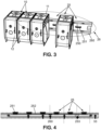
- the frame 20 of the machine may comprise one or more alignments of locations 26 arranged side by side, each alignment comprising for example between 2 and 10 locations for modules.
- the machine 1 may comprise two alignments 26 of locations 25 of modules 10, arranged parallel to each other, on either side of the support plate of the object to be manufactured. This makes it possible to use a symmetrical configuration of the machine and of the moving device 30, which is detailed later.
- the machine 1 may comprise an alignment of locations 26 located on a peripheral wall of the machine, and in particular a bottom wall opposite a wall through which an operator can access the enclosure of the machine.
- the locations are made on a support part 260 secured to the frame, which may be a profile or a formed part.
- This part advantageously comprises the mechanical 250 and electrical 251 connectors of each location, which are therefore regularly arranged along the length of the part, and a housing in which an electronic card 252 is mounted, for example a printed circuit, on which the electrical connectors 251 are mounted, the electronic card 252 further comprising at least one additional connector 253 for establishing a connection with the main controller 41.
- the electrical connectors 252 of the locations and of the docking stations are configured to ensure communication between the docking station and the main controller and also to provide the electrical power supply to the docking station, and where appropriate to the manufacturing head when it is mounted in the station.
- the electrical connectors are advantageously pin connectors, without wires, for structural simplification of the machine. These can typically be spring connectors.
- Each location 25 preferably comprises at least two mechanical connectors 250 adapted to cooperate with complementary connectors of a docking station.
- the mechanical connectors are for example configured to allow a mechanical connection, for example by snapping or guiding in dedicated housings followed by fixing by screws.
- the moving device 30 comprises a movable carriage 31 in a plane parallel to the support plate 24.
- the movement of the movable carriage is controlled along two perpendicular axes denoted X and Y, these two axes being parallel to the plane of the support plate 24.
- the movement device 30 may comprise an arm 32, movable in translation in a direction Y parallel to the alignment or alignments of the modules, the arm 32 extending in a direction X perpendicular to Y, and the carriage 31 being mounted movable in translation in the arm 32 in this direction X.
- the moving device 30 comprises at least one belt 33 on which the carriage 31 is mounted, and motors 34 adapted to drive the belt in motion.
- the belt 33 forms a closed contour inside which the locations 25 of the manufacturing modules are located, which allows the mobile carriage 31 to easily access the manufacturing head 12 of a module 10 to come and collect it and deposit it.
- the belt also passes through housings provided for this purpose in the moving arm 32 of the carriage.
- the arm 32 for moving the carriage may comprise two symmetrical longitudinal parts 320 connected to each other by end parts 321.
- the longitudinal parts 320 are spaced apart by an interval allowing the movable carriage 31 to be positioned and moved therein, and each part 320 comprises a longitudinal housing 322 for a portion of the belt.
- the movable carriage 31 is mounted in a slide on longitudinal rods 323 carried by each longitudinal part.
- the end pieces 321 can carry guide pulleys 324 of the belts, and possibly rollers 325 allowing them to be mounted on rails 35 provided for this purpose, in order to move the arm in the Y direction.
- the end pieces 321 advantageously have a U shape, comprising two uprights 326 connected respectively to each longitudinal piece, and separated from each other by a gap wide enough to allow the carriage and a head 12 of a manufacturing module to pass.
- the end pieces 321 are thus advantageously sized so that the gap between the uprights 326 is greater than the dimension of a manufacturing module head.
- the uprights 326 are connected by a base 327 which is slidably mounted in a respective rail 35 and can comprise the rollers 325 for this purpose.
- the contour thus formed by the belt 33 has an H profile.
- the moving device actually comprises two belts 33, 33' superimposed one above the other in the Z direction, these two belts moving in opposite directions.
- the motorization is advantageously provided by four stepper motors 34 distributed to two motors per belt. This configuration makes it possible to increase the total motor torque available for the movements, and thus to have significant gains in speed and acceleration, to better distribute the forces on the belts and to authorize the use of flexible belts with small pitches, and to generally better balance the forces which are exerted on the moving parts, namely the moving arm 32 and the carriage 31.
- the carriage 31 may be equipped with an end-of-travel sensor.
- the end-of-travel sensor may be an optical sensor (not shown.
- a mark may be arranged to obscure this sensor when the carriage is in the positive X zone.
- the transition between the masked and unmasked state of the sensor makes it possible to identify the zero position on the X axis.
- the state of the sensor when of the zeroing command indicates the direction of movement to find zero, an unmasked state indicating a negative X value, thus a movement aimed at incrementing X, and a masked state a positive position which implies an inverse movement.
- the carriage 31 may further comprise an image sensor 310 such as a camera or a microscope, making it possible to acquire images of a portion of the support plate, for example to calibrate the position of certain manufacturing module heads, as described in more detail below.
- an image sensor 310 such as a camera or a microscope, making it possible to acquire images of a portion of the support plate, for example to calibrate the position of certain manufacturing module heads, as described in more detail below.
- the mechanical coupling means between on the one hand a docking station 11 and a manufacturing head 12, and on the other hand between the carriage 31 and a manufacturing head 12, are electromagnetic, for rapid capture and in order to avoid wear of the parts.
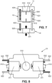
- each docking station 11 as well as the carriage 31 advantageously comprise a controlled magnetic suction cup 510, 511 (i.e. an electromagnet), and the manufacturing head 12 comprises, on two opposite faces, a counterplate 512 made of a magnetic material on which the magnetic field generated by the suction cup can result in a magnetic force.
- the docking station 10 and the manufacturing head 12 on the one hand, and the carriage 31 and the head 12 on the other hand may comprise means for guiding and controlling the alignment of the parts.
- the docking station 11 may comprise a fork comprising at least two axes 520 adapted to be received in corresponding bores 521 of the manufacturing head 12 of a module.
- the manufacturing head 12 of a module may also carry a fork whose axes are received in bores of the docking station.
- the carriage 31 may comprise a fork comprising at least two axes 522 received in corresponding bores 523 of the print head, or vice versa.
- the forks are carried by the docking station 11 and the carriage 31, and the manufacturing head 12 comprises through bores 521, 523 adapted to receive on one side the axes 520 of the fork carried by the docking station 11, and on the opposite side the axes 522 of the fork carried by the carriage 31.
- one of the axes of the docking station and the carriage can be hollow, and an optical transmitter 524/receiver 525 assembly can be installed in these hollow axes, which makes it possible to confirm the alignment of the carriage relative to the module when it comes to retrieve or deposit a print head in its docking station.
- an infrared laser diode 524 may be positioned at the bottom of the hollow shaft of the docking station, and an infrared photodiode 525 may be positioned at the bottom of the hollow shaft opposite on the carriage 31, with detection of light from the diode by the photodiode confirming alignment of the carriage 31, the head, and the docking station.
- Each manufacturing head 12 also comprises, on two opposite faces, electrical contacts (not shown) adapted to cooperate with electrical contacts 531, 532 of a part of the docking station and on the other hand of the carriage 31, these electrical contacts making it possible to electrically power, respectively by the docking station 11 or by the carriage 31, components contained in the manufacturing head 12.
- the manufacturing head 12 hereinafter called the print head, comprises a heating element for melting the wire, and this heating element is electrically powered by means of the electrical contacts.
- the carriage 31 is connected to the main controller 41, for example by a wired connection, for receiving instructions from the main controller 41 to move the manufacturing head 12, but also to transmit control instructions for the manufacturing head 12.
- the manufacturing heads 12 of certain manufacturing modules may also comprise an electronic card comprising a controller 129, which is configured to receive instructions and to control electronic components in accordance with the instructions received, in particular by applying control parameters appearing in the instructions (for example: fan speed, heating temperature, etc.).
- a controller 129 which is configured to receive instructions and to control electronic components in accordance with the instructions received, in particular by applying control parameters appearing in the instructions (for example: fan speed, heating temperature, etc.).
- the electrical contacts of the manufacturing heads 12, docking stations 11 and the mobile carriage 31 are also adapted to allow the transmission of instructions, either from the docking station 11 or from the main controller 41 via the carriage, depending respectively on whether the manufacturing head is connected to the docking station or to the carriage.
- the means of coupling to a module head i.e. magnetic, mechanical and/or electrical coupling are arranged on a face of the docking station different from, and advantageously opposite to, the face carrying the mechanical and electrical connectors allowing the docking station to be mounted on the module location of the machine frame.
- the carriage 31 comprises at least one motor 311 and a coupling member 312, typically a dog clutch, with an output shaft of the motor.
- Certain heads 12 of manufacturing modules 10, depending on their function, may comprise moving parts that can be driven by a motor, and in this case they advantageously comprise a coupling member adapted to cooperate with that 312 of the carriage 31 to be able to ensure a drive of parts of the head by the motor of the carriage.
- the docking station 11 of the module may also comprise a motor 111 and a coupling member 112, and an opposite face of the head of the module also comprises a coupling member (not shown) adapted to cooperate with that of the station.
- the implementation of moving mechanical parts of the manufacturing head 12 may be ensured by the docking station 11 or by the carriage 31, depending on whether the manufacturing head 12 is assembled to one or the other.
- the mobile carriage 31 has a symmetrical configuration allowing it to couple with a manufacturing head 12 of the modules 10 of the two alignments.
- the mobile carriage 31 comprises two motors 311 and comprises, on two faces opposite, in the X direction, i.e. the faces which come opposite the heads 12 of the manufacturing modules, the coupling elements described above, i.e. magnetic suction cup 511, fork or bores, electrical connectors 532, motor coupling member 312.
- the optical sensor mentioned above can be positioned in the center of the carriage.
- the carriage 31 can also include encoders for detecting the position of the motors as well as fans for cooling each motor and cooling the deposited material, if applicable.
- the print head 12 of a fused filament deposition printing module comprises a nozzle 120, the diameter of which is constant and determined, and a heating element 121 for melting the filament before depositing it.
- the docking station 11 is configured to supply the print head 12 with filament from a spool 13 of filament.
- the modular machine 1 comprises at least as many locations for spools 13 of filament as locations for manufacturing modules, the locations for the spools preferably being positioned under the locations of the modules. Some of these locations may be equipped for conditioning the spools of filament by controlling the temperature and humidity.
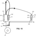
- this configuration allows the filament to pass through an internal channel 113 provided for this purpose of a docking station 11 of a printing module 10, the filament entering the channel at a lower wall 114 of the docking station, and emerging from the docking station at an upper wall 115, where it is supported by a flexible guide rod 116 mounted on the docking station, this guide rod making it possible to ensure that the filament does not fall onto the printing area and does not form an obstacle in the path of the carriage or a manufacturing head 12.
- the dimensions of the guide rod are calculated to allow all parts of the working area of the support plate 24 to be reached, without exerting a restoring force which would be too great and which could hinder the precision of the head.
- the filament is then introduced into an internal channel 122 of a print head 12, for example at an upper face 123 of the head, where it is conveyed to the nozzle arranged on a lower face 124 of the head, facing the support plate 25.
- the manufacturing machine 1 also comprises a tray 14 for recovering filament leaders or remnants arranged below the module locations.
- This tray can be interposed between the module locations 10 and the reel locations 13, while maintaining a passage for a filament between each reel location and each module location.
- the docking station 11 of the printing module 10 is configured to supply the print head 12 with filament.
- it comprises a motor 111 and a drive device 117 for the filament driven by the motor.
- the same motor drives the coupling member 112 and the drive device 117.
- This drive device 117 can be disengaged once the filament is loaded into the print head.
- the docking station 11 is configured to monitor a set of parameters relating to the filament and/or to the consumption of filament by the print head 12, and to comprise in this regard one or more sensors.
- the docking station comprises at least one sensor, for example an optical sensor 118, adapted to detect the filament, and to detect a breakage or an absence of filament.
- the docking station may also comprise an encoder 119 adapted to measure a length of unwound filament.
- the secondary controller 110 of the docking station is configured to communicate to the main controller 41 the length of filament consumed measured by the encoder, as well as alerts if an event of the breakage or absence of filament type is detected.
- the main controller 41 can, upon receiving an alert on a break or absence of filament, interrupt a manufacturing process in progress (in particular by sending to the print head 12, via the mobile carriage, instructions to stop manufacturing) and produce an alert on the human-machine interface intended for the operator.
- the main controller 41 is also configured to compare the length of filament consumed measured by the encoder with a theoretical length which is determined according to the geometry of the part to be produced, and generate an alert in the event of an inconsistency between the two.
- the print head 12 also comprises a filament drive device 125, which is driven either by the docking station motor or by the carriage motor, depending on whether the print head is mounted on one or the other, by means of the coupling members provided for this purpose and described above.
- the heating device 121 is interposed between the drive device and the nozzle 120, allowing the filament to be melted at the time of its deposition.
- the docking station 11 of a fused filament deposition printing module 10 is also adapted to perform the preheating and preloading of a filament in the head in masked time, that is to say during the operation of another manufacturing module, in preparation for the operation of the printing module.
- the main controller 41 is configured to command the secondary controller 110 of the docking station 11 of the printing module 10 to perform this preheating and preloading during the operation of a previous manufacturing module in the sequence.
- the docking station 11 of certain manufacturing modules, and in particular fused deposition modeling printing modules, may also be configured to clean the head so as to prevent material residues from being deposited on the part being manufactured.
- the docking station may in this regard comprise a cleaning device (not shown), static or not, motorized or not, which is configured to clean the head when the latter is replaced by the mobile carriage in the docking station or when it is retrieved by the mobile carriage for use.
- a print module docking station is configured to communicate configuration information to the main controller during a module initialization phase.
- this configuration information may include a set of module operating parameters, including for example a set temperature for melting the filament of the module, a printing speed, a nozzle diameter, a fan speed, a waiting temperature, and a heating time etc.
- the main controller 41 is configured to generate a sequence of instructions for manufacturing the part.
- Additional calibration may be implemented for some manufacturing modules. For example, since the X and Y position of a nozzle relative to the print head is not necessarily the same for all printing modules, this position may be determined by printing a test pattern and using the image sensor 310 of the carriage to determine the coordinates of this printed pattern, and deduce the position of the nozzle therefrom. Other tools such as a laser tool, an engraving tip or a writing module may be subject to a similar calibration, having however previously installed an additional coating on the support plate so as not to leave a lasting trace on it.
- the modular machine described above therefore allows the implementation of part manufacturing processes involving the successive intervention of various tools, i.e. comprising at least two manufacturing steps involving two different manufacturing modules. Between each manufacturing step, the carriage returns the manufacturing head used to the corresponding docking station and then recovers the manufacturing head necessary for the implementation of the following step.
Landscapes
- Engineering & Computer Science (AREA)
- Chemical & Material Sciences (AREA)
- Materials Engineering (AREA)
- Manufacturing & Machinery (AREA)
- Physics & Mathematics (AREA)
- Mechanical Engineering (AREA)
- Optics & Photonics (AREA)
- Robotics (AREA)
- Automatic Assembly (AREA)
Applications Claiming Priority (1)
| Application Number | Priority Date | Filing Date | Title |
|---|---|---|---|
| FR2308168A FR3151522B1 (fr) | 2023-07-28 | 2023-07-28 | Machine modulaire de fabrication par addition, soustraction ou transformation de matière |
Publications (1)
| Publication Number | Publication Date |
|---|---|
| EP4497571A1 true EP4497571A1 (de) | 2025-01-29 |
Family
ID=88689675
Family Applications (1)
| Application Number | Title | Priority Date | Filing Date |
|---|---|---|---|
| EP24191112.2A Withdrawn EP4497571A1 (de) | 2023-07-28 | 2024-07-26 | Modulare maschine zur herstellung durch addition, subtraktion oder materialumwandlung |
Country Status (2)
| Country | Link |
|---|---|
| EP (1) | EP4497571A1 (de) |
| FR (1) | FR3151522B1 (de) |
Citations (3)
| Publication number | Priority date | Publication date | Assignee | Title |
|---|---|---|---|---|
| WO2022204794A1 (en) * | 2021-03-29 | 2022-10-06 | Mosaic Manufacturing Ltd. | Apparatus, methods and systems for automatic, configurable manufacturing workflow for additive manufacturing systems |
| US11707889B1 (en) | 2020-08-19 | 2023-07-25 | Sciperio, Inc | Modular mobile direct digital manufacturing systems (M2DDM) |
| US20230236552A1 (en) * | 2020-12-18 | 2023-07-27 | Strong Force Vcn Portfolio 2019, Llc | Digital-Twin-Enabled Artificial Intelligence System for Distributed Additive Manufacturing |
-
2023
- 2023-07-28 FR FR2308168A patent/FR3151522B1/fr active Active
-
2024
- 2024-07-26 EP EP24191112.2A patent/EP4497571A1/de not_active Withdrawn
Patent Citations (3)
| Publication number | Priority date | Publication date | Assignee | Title |
|---|---|---|---|---|
| US11707889B1 (en) | 2020-08-19 | 2023-07-25 | Sciperio, Inc | Modular mobile direct digital manufacturing systems (M2DDM) |
| US20230236552A1 (en) * | 2020-12-18 | 2023-07-27 | Strong Force Vcn Portfolio 2019, Llc | Digital-Twin-Enabled Artificial Intelligence System for Distributed Additive Manufacturing |
| WO2022204794A1 (en) * | 2021-03-29 | 2022-10-06 | Mosaic Manufacturing Ltd. | Apparatus, methods and systems for automatic, configurable manufacturing workflow for additive manufacturing systems |
Also Published As
| Publication number | Publication date |
|---|---|
| FR3151522B1 (fr) | 2025-08-01 |
| FR3151522A1 (fr) | 2025-01-31 |
Similar Documents
| Publication | Publication Date | Title |
|---|---|---|
| CA1233547A (fr) | Procede et dispositif de placement interactif sur un support de profils a des fins de tracage et/ou de decoupe | |
| FR2664043A1 (fr) | Lentille a grandissement variable pour un appareil de prise de vues a profondeur de champ variable. | |
| FR2721395A1 (fr) | Procédé de repérage positionnel d'un trièdre dans l'espace et dispositif pour la mise en Óoeuvre de ce procédé. | |
| FR2514100A1 (fr) | Procede de montage automatique d'un rouleau d'une feuille continue sur un support | |
| FR2934911A1 (fr) | Systeme automatise de guidage et de reconnaissance et procede pour ledit systeme | |
| FR2631786A1 (fr) | Procede d'inspection electro-optique de cigarettes | |
| FR2664065A1 (fr) | Detecteur a fibres optiques pour appareil de prise de vues a profondeur de champ variable. | |
| WO2020229054A1 (en) | Transport system and method for printing plates | |
| CN113245242A (zh) | 一种载玻片缺陷检测分拣系统 | |
| EP1934122B1 (de) | Verfahren zum automatischen und sequenziellen laden von gegenständen und entsprechende ausrüstung | |
| EP0494014B1 (de) | Erzeugung einer Liste von Gegenständen für die Beladung von Behältern | |
| FR2514171A1 (fr) | Procede et dispositif de generation d'un dessin verifie | |
| EP0618505B1 (de) | Vorrichtung zur Belichtung einer doppelseitigen Plattenschaltung durch Druckplatten | |
| EP4497571A1 (de) | Modulare maschine zur herstellung durch addition, subtraktion oder materialumwandlung | |
| EP1671192A2 (de) | Verfahren zum kalibrieren einer brillenlinsen-durchdringungsmaschine, einrichtung zur implementierung eines solchen verfahrens und eine solche einrichtung umfassende brillenlinsen-bearbeitungs-vorrichtung | |
| EP0036826B1 (de) | Vorrichtung zur automatischen Herstellung elektronischer Hybridenschaltungen | |
| FR2602879A1 (fr) | Procede et appareil de production d'un modele pour une ouverture de lentille dans une monture de lunettes | |
| EP0349438B1 (de) | Verfahren und Vorrichtung für die Identifizierung eines Schreibgerätes | |
| CN113335888B (zh) | 生产线 | |
| EP0359664A1 (de) | Vorrichtung zum Messen einer Querabmessung eines im wesentlichen zylindrischen Objektes | |
| EP0930954B1 (de) | Herstellungssystem einer optischen linse ausgehend von einem rohling | |
| EP0036374A1 (de) | Verfahren und Vorrichtung zum Schweissen mit automatischem Folgen der Schweissnaht | |
| JP2001063190A (ja) | 濃度測定方法及びその測定装置 | |
| CN207840398U (zh) | 一种紫外激光加工设备 | |
| FR2602880A1 (fr) | Systeme et procede de fabrication de modele de verre de lunettes |
Legal Events
| Date | Code | Title | Description |
|---|---|---|---|
| PUAI | Public reference made under article 153(3) epc to a published international application that has entered the european phase |
Free format text: ORIGINAL CODE: 0009012 |
|
| STAA | Information on the status of an ep patent application or granted ep patent |
Free format text: STATUS: THE APPLICATION HAS BEEN PUBLISHED |
|
| AK | Designated contracting states |
Kind code of ref document: A1 Designated state(s): AL AT BE BG CH CY CZ DE DK EE ES FI FR GB GR HR HU IE IS IT LI LT LU LV MC ME MK MT NL NO PL PT RO RS SE SI SK SM TR |
|
| STAA | Information on the status of an ep patent application or granted ep patent |
Free format text: STATUS: THE APPLICATION IS DEEMED TO BE WITHDRAWN |
|
| 18D | Application deemed to be withdrawn |
Effective date: 20250730 |