EP4497613A1 - Pneumatique - Google Patents
Pneumatique Download PDFInfo
- Publication number
- EP4497613A1 EP4497613A1 EP24187427.0A EP24187427A EP4497613A1 EP 4497613 A1 EP4497613 A1 EP 4497613A1 EP 24187427 A EP24187427 A EP 24187427A EP 4497613 A1 EP4497613 A1 EP 4497613A1
- Authority
- EP
- European Patent Office
- Prior art keywords
- tire
- raised
- raised portion
- protruding height
- outward
- Prior art date
- Legal status (The legal status is an assumption and is not a legal conclusion. Google has not performed a legal analysis and makes no representation as to the accuracy of the status listed.)
- Pending
Links
Images


Classifications
-
- B—PERFORMING OPERATIONS; TRANSPORTING
- B60—VEHICLES IN GENERAL
- B60C—VEHICLE TYRES; TYRE INFLATION; TYRE CHANGING; CONNECTING VALVES TO INFLATABLE ELASTIC BODIES IN GENERAL; DEVICES OR ARRANGEMENTS RELATED TO TYRES
- B60C13/00—Tyre sidewalls; Protecting, decorating, marking, or the like, thereof
- B60C13/001—Decorating, marking or the like
-
- B—PERFORMING OPERATIONS; TRANSPORTING
- B60—VEHICLES IN GENERAL
- B60C—VEHICLE TYRES; TYRE INFLATION; TYRE CHANGING; CONNECTING VALVES TO INFLATABLE ELASTIC BODIES IN GENERAL; DEVICES OR ARRANGEMENTS RELATED TO TYRES
- B60C13/00—Tyre sidewalls; Protecting, decorating, marking, or the like, thereof
- B60C13/002—Protection against exterior elements
-
- B—PERFORMING OPERATIONS; TRANSPORTING
- B60—VEHICLES IN GENERAL
- B60C—VEHICLE TYRES; TYRE INFLATION; TYRE CHANGING; CONNECTING VALVES TO INFLATABLE ELASTIC BODIES IN GENERAL; DEVICES OR ARRANGEMENTS RELATED TO TYRES
- B60C13/00—Tyre sidewalls; Protecting, decorating, marking, or the like, thereof
- B60C13/02—Arrangement of grooves or ribs
Definitions
- the present invention relates to a tire.
- Japanese Unexamined Patent Application Publication No. 2019-167067 has proposed a tire including a sidewall portion provided with a mark indicating portion having one or more marks.
- the mark indicating portion has a base portion protruding at a constant height from the surface of the sidewall portion.
- the tires configured as such are said to improve the visibility of the marks.
- the present invention was made in view of the above issue, and a primary object thereof is to provide a tire capable of improving the life performance while maintaining the visibility of the marks.
- a tire including:
- the tire of the present invention improves the life performance while maintaining the visibility of the marks.
- FIG. 1 is a right half of a tire meridian section of a tire 1 passing all through a tire rotational axis thereof (not shown).
- FIG. 1 shows a pneumatic tire for passenger cars as a preferred form, more specifically, a tire for commercial vehicles that are expected to be used under relatively high loads.
- the present invention may also be applied to pneumatic tires for light trucks and for heavy duty and to non-pneumatic tires that are not filled with pressurized air inside the tires.
- standard state refers to a state in which the tire 1 is mounted on a standard rim (not shown), inflated to a standard inner pressure, and loaded with no tire load.
- standard rim refers to a wheel rim specified for the concerned tire by a standard included in a standardization system on which the tire is based, for example, the "normal wheel rim” in JATMA, "Design Rim” in TRA, and “Measuring Rim” in ETRTO.
- standard inner pressure refers to air pressure specified for the concerned tire by a standard included in a standardization system on which the tire is based, for example, the maximum air pressure in JATMA, the maximum value listed in the "TIRE LOAD LIMITS AT VARIOUS COLD INFLATION PRESSURES" table in TRA, and "INFLATION PRESSURE” in ETRTO.
- the tire 1 includes a pair of sidewall portions 3 (one of the sidewall portions 3 is shown in FIG. 1 ).
- the tire 1 further includes a pair of bead portions 4 (one of the bead portions 4 is shown in FIG. 1 ) each located radially inside a respective one of the sidewall portions 3, and a tread portion 2 connecting the sidewall portions 3.
- FIG. 2 is an enlarged side view of the tire 1.
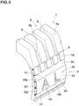
- FIG. 3 is a perspective cross-sectional view of the tire 1. As shown in FIGs. 1 through 3 , at least one of the pair of the sidewall portions 3 is provided with a raised portion 10 raised outward in a tire axial direction from a reference surface (3s).
- the tire 1 in the present embodiment has the raised portion 10 on each sidewall portion 3. It should be noted that the tire 1 may have the raised portion 10 on only one of the sidewall portions 3.
- the raised portion 10 extends continuously in a tire circumferential direction in an annular shape.
- the raised portion 10 configured as such protects the sidewall portions 3 continuously in the tire circumferential direction.
- the raised portion 10 also forms a tire maximum width position (M).
- the area near the tire maximum width position (M) is the area where is most likely to contact with curbs and other objects protruding from the road surface. Therefore, the raised portion 10 which forms the tire maximum width position (M) effectively suppresses damage to carcass plies (not shown) and the like due to contact with curb stones and the like, thereby, it is possible that protection property and thus the life performance are improved.
- the "tire maximum width position (M)" is the position where the reference surface (3s) extends outermost in the tire axial direction.
- the raised portion 10 is provided with a mark portion 13 including a plurality of characters recessed axially inward.
- the mark portion 13 configured as such can maintain high visibility of the mark portion 13 even if the raised portion 10 is worn away by curbs and the like, for example. Further, the mark portion 13 reduces the rubber volume of the raised portion 10, which suppresses heat generation in the sidewall portions 3 during running, therefore, it is possible that the durability and thus the life performance of the tire 1 are improved. Excessive heat generation in the tire 1 deteriorates the rubber in the sidewall portions 3, resulting in poor steering stability.
- the above-mentioned "characters" include European letters, numbers, and symbols, which show the name of the tire manufacturer, brand name, size, and the like, for example.
- the mark portion 13 in the present embodiment is formed only by a plurality of characters, for example.
- the mark portion 13 includes recessed spaces 15. Each recessed space 15 forms a letter.
- the tread portion 2 in the present embodiment is provided with a plurality of shoulder blocks 5 including tread edges (Te) and shoulder axial grooves 6 extending in the tire axial direction between the shoulder blocks adjacent to each other so as to each cross a respective one of the tread edges (Te).
- the tread edges (Te) are the axially outermost positions where the tire 1 contacts a plane under a standard tire load loaded state.
- the standard tire load loaded state is a state in which the tire 1 in the standard state is in contact with the plane with zero camber angle by being loaded with a standard tire load.
- the term "standard tire load” refers to a tire load specified for the concerned tire by a standard included in a standardization system on which the tire is based, for example, the "maximum load capacity" in JATMA, maximum value listed in "TIRE LOAD LIMITS AT VARIOUS COLD INFLATION PRESSURES" table in TRA, and "LOAD CAPACITY" in ETRTO.
- each of the sidewall portions 3 in the present embodiment includes an annular portion 9 extending continuously in the tire circumferential direction centered on the tire rotational axis.
- the annular portion 9 is formed so as to be raised axially outward from the reference surface (3s), for example.
- the annular portion 9 is located radially outside the tire maximum width position (M).
- the annular portion 9 in the present embodiment is connected with the shoulder axial grooves 6.
- a separation distance (Hf) between the annular portion 9 and a bead baseline (BL) in the tire radial direction is preferably 70% or more and more preferably 75% or more of a tire section height (H).
- the separation distance (Hf) is preferably 90% or less and more preferably 85% or less of the tire section height (H).
- the "tire section height (H)” is a radial distance from the bead baseline (BL) to the radially outermost position of the tire 1.
- the "bead baseline (BL)” is a tire axial direction line that passes through the rim diameter position.
- the reference surface (3s) is formed by a hidden surface and an outer surface.
- the hidden surface is recessed in the tire axial direction from the surface of the sidewall portion 3 and hidden by partial unevenness such as the annular portion 9, the raised portion 10, and protective ribs for preventing rim detachment.
- the outer surface of the reference surface (3s) is connected smoothly with the hidden surface and is a part of the surface of the sidewall portion 3.
- the reference surface (3s) of the present embodiment is formed so as to smoothly connect groove bottoms (6s) of the shoulder axial grooves 6 and an outer surface (4s) of a respective one of the bead portions 4 in the tire meridian section.
- the raised portion 10 is formed so that a length (La) thereof in the tire radial direction is continuously the same in the tire circumferential direction, for example. It should be noted that the raised portion 10 may have the length (La) varying in the tire circumferential direction (not shown).
- the raised portion 10 in the present embodiment has a middle position (10p) in the tire radial direction located radially outside the tire maximum width position (M). Thereby, it is possible that damage to the tire 1 is suppressed more effectively.
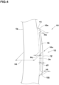
- FIG. 4 is an enlarged view of the raised portion 10 of FIG. 1 .
- the raised portion 10 includes an outer edge (10e) in the tire radial direction, an inner edge (10i) in the tire radial direction, and a middle portion (10c) in the tire radial direction.
- the raised portion 10 has a protruding height in the tire axial direction from the reference surface (3s).
- the "protruding height” means a length in the normal direction of the reference surface (3s) in the tire meridian section.
- the middle portion (10c) is a portion between the outer edge (10e) and the inner edge (10i) and includes the middle position (10p) (shown in FIG. 1 ) between the outer edge (10e) and the inner edge (10i).
- the raised portion 10 includes wall surfaces 11 extending in the tire axial direction from the reference surface (3s) and an outward surface 12 connected to the wall surfaces 11, located axially outermost, and facing outward in the tire axial direction, for example.
- the wall surfaces 11 extend continuously in the tire circumferential direction in the present embodiment.
- the outer edge (10e) and the inner edge (10i) are formed at the intersections of the wall surfaces 11 and the outward surface 12.
- the outward surface 12 of the present embodiment is formed in an arc shape.
- the outward surface 12 configured as such can reduce damage by dispersing the impact caused by contact with curbs in multiple directions. It should be noted that the outward surface 12 may be formed in a shape tapered axially outward in the tire meridian section, for example.
- the middle portion (10c) of the raised portion 10 has a protruding height (He) larger than a protruding height (He) at the outer edge (10e) and a protruding height (Hi) at the inner edge (10i), for example. Therefore, the tire volume is reduced on the outer edge (10e) side and the inner edge (10i) side to suppress heat generation during running as well as the protection property is improved in the middle portion (10c).
- the protruding height of the raised portion 10 in the present embodiment is continuously decreasing from the middle portion (10c) to the outer edge (10e) and the inner edge (10i).
- the protruding height (He) of the middle portion (10c) is 4 or less times the protruding heights (He) and (Hi) at the outer edge (10e) and inner edge (10i).
- the protruding height (He) of the middle portion (10c) is more preferably 1.1 or more times the protruding heights (He) and (Hi) of the outer edge (10e) and the inner edge (10i), and more preferably 2 or less times the protruding heights (He) and (Hi).
- the protruding height (He) of the middle portion (10c) is from 0.5 to 5 mm, for example.
- the protruding height (He) of the middle portion (10c) is preferably 5% or more, more preferably 10% or more of a tire thickness (Ht) passing through the middle portion (10c), i.e., the tire thickness (Ht) at the middle portion (10c).
- the protruding height (Hc) is preferably 50% or less, more preferably 35% or less of the tire thickness (Ht). Since the protruding height (He) of the middle portion (10c) is 5% or more of the tire thickness (Ht), the sidewall portions 3 can be effectively protected. Since the protruding height (He) of the middle portion (10c) is 50% or less of the tire thickness (Ht), excessive increase in mass due to the mark portion 13 can be suppressed.
- the tire thickness (Ht) means a length in the normal direction of the tire inner cavity surface (1b), and is the length between the tire inner cavity surface (1b) and the outward surface 12.
- the length (La) of the raised portion 10 in the tire radial direction is preferably 5% or more, more preferably 10% or more of the tire section height (H) (shown in FIG. 1 ).
- the length (La) is preferably 30% or less, more preferably 25% or less of the tire section height (H). Since the length (La) of the raised portion 10 is 5% or more of the tire section height (H), the sidewall portion 3 can be effectively protected from coming into contact with curbs. Since the length (La) of the raised portion 10 is 30% or less of the tire section height (H), the rubber volume of the raised portion 10 can be suppressed from becoming excessively large, thereby, heat generation during running can be suppressed.
- the mark portion 13 has a depth (d1) (the depth of the recessed space 15).
- the depth (d1) is preferably 30% or more, more preferably 40% or more of the protruding height (He) of the middle portion (10c).
- the depth (d1) is preferably 80% or less, more preferably 70% or less of the protruding height (He) of the middle portion (10c). Since the depth (d1) of the mark portion 13 is 30% or more of the protruding height (He) of the middle portion (10c), the mass of the tire 1 is effectively reduced, therefore, it is possible that heat generation during running is suppressed.
- the depth (d1) of the mark portion 13 is 80% or less of the protruding height (He) of the middle portion (10c), excessive decrease in the rigidity of the raised portion 10 can be suppressed, thereby, it is possible that damage caused by contact with curbs is suppressed.
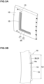
- FIG. 5A is an enlarged perspective view of the mark portion 13 of FIG. 2 .
- FIG. 5B is a cross-sectional view taken along A-A line in FIG. 5A .
- the recessed space 15 in the present embodiment has a serration 20 in which a plurality of ridges 21 are arranged.
- the serration 20 configured as such has the effect of making the letters appear darker, improving the visibility of the mark portion 13, and suppressing the heat generation in the raised portion 10 during running.
- Each of the ridges 21 extends in the tire radial direction in order to effectively support the load of the tire 1 in the present embodiment.
- the ridges 21 have a maximum height (Hs) which is preferably 30% or more, more preferably 50% or more of the depth (d1) of the recessed space 15 (shown in FIG. 4 ).
- the maximum height (Hs) is preferably 70% or less, more preferably 60% or less. Since the maximum height (Hs) of the ridges 21 is 40% or more of the depth (d1) of the recessed space 15, it is highly effective in absorbing the light irradiated on the recessed space 15, which improves the visibility of the mark portion 13. Since the maximum height (Hs) of ridges 21 is 70% or less of the depth (d1) of the recessed space 15, excessive mass increase due to ridges 21 is suppressed.
- the recessed space 15 (above-described letter) has a length (Lb) in the tire radial direction which is preferably 50% or more, more preferably 70% or more of the length (La) in the tire radial direction of the raised portion 10.
- the length (Lb) of the recessed space is preferably 90% or less, more preferably 80% or less of the length (La) of the raised portion 10. Since the length (Lb) of the recessed space 15 is 50% or more of the length (La) of the raised portion 10, it is possible that the mark portion 13 (letter) is clearly recognized. Since the length (Lb) of the recessed space 15 is 90% or less of the length (La) of the raised portion 10, the rigidity of the raised portion 10 is maintained, therefore, it is possible that the damage caused by contact with curbs is suppressed.
- one of the pair of the sidewall portions 3 in the present embodiment has outer raised portions 16 raised outward in the tire axial direction from the reference surface (3s).
- the outer raised portions 16 in the present embodiment are located radially outside the raised portion 10. It is possible that the outer raised portions 16 configured as such further suppress the damage caused by contact of the sidewall portions 3 with curbs.
- the outer raised portions 16 and the raised portion 10 are separated and spaced apart by the reference surface (3s) (the above-mentioned outer surface), for example.
- the outer raised portions 16 in the present embodiment are located radially inside the annular portion 9 and are connected to the annular portion 9.
- the multiple outer raised portions 16 are arranged in the tire circumferential direction. Specifically, each of the outer raised portions 16 is formed in a rectangular block shape in a side view of the tire 1. Further, the outer raised portions 16 adjacent to each other in the tire circumferential direction are separated and spaced apart by the reference surface (3s) (the outer surface mentioned above). These outer raised portions 16 configured as such suppress excessive increase in mass of the tire 1.
- a length (Wc) in the tire circumferential direction of each of the outer raised portions 16 is preferably 40% or more, more preferably 50% or more of a circumferential pitch (P) of the outer raised portions 16.
- the length (Wc) is preferably 90% or less, more preferably 80% or less of the circumferential pitch (P).
- the length (Wc) and the circumferential pitch (P) of the outer raised portions 16 are measured at outer ends (16e) in the tire radial direction of the outer raised portions 16.
- Each of the outer raised portions 16 has a length (Lc) in the tire radial direction which is smaller than the length (La) in the tire radial direction of the raised portion 10, for example.
- the raised portion 10 can effectively suppress damage near the tire maximum width position (M) where damage caused by curb stones is most likely to occur. Further, an excessive increase in the mass of the tire 1 can be suppressed in the portion radially inside the annular portion 9, where damage is relatively less likely to occur.
- the length (Lc) of the outer raised portions 16 is preferably 40% or more, more preferably 45% or more of the length (La) of the raised portion 10.
- the length (Lc) of the outer raised portions 16 is preferably 60% or less, more preferably 55% or less of the length (La) of the raised portion 10.
- the protruding height (Hb) in the tire axial direction of the outer raised portions 16 from the reference surface (3s) is equal to or less than the protruding height (He) of the middle portion (10c). Since the area where outer raised portions 16 are provided is less likely to come into contact with curbs than the area around the tire maximum width position (M), it is possible that damage of the above region caused by the curbs is suppressed as well as the heat generation is suppressed to maintain the durability of the tire 1 at a high level by setting the protruding height (Hb) equal to or smaller than the protruding height (Hc).
- the protruding height (Hb) is preferably 30% or more, more preferably 40% or more of the protruding height (Hc).
- the protruding height (Hb) is preferably 90% or less, more preferably 60% or less of the protruding height (Hc).
- the protruding height (Hb) of the outer raised portions 16 in the present embodiment is smaller than a protruding height (Hd) in the tire axial direction of the annular portion 9. Therefore, the durability of the tire 1 is further maintained high.
- the protruding height (Hb) is preferably 55% or more, more preferably 60% or more of the protruding height (Hd).
- the protruding height (Hb) is preferably 75% or less, more preferably 70% or less of the protruding height (Hd).
- one of the pair of the sidewall portions 3 includes a first rubber portion G1 forming the raised portion 10 and a second rubber portion G2 forming the reference surface (3s).
- the first rubber portion G1 and the second rubber portion G2 are adjacent to each other in the tire axial direction, for example.
- the second rubber portion G2 forms the portion axially inside the reference surface (3s) and is disposed between the first rubber portion G1 and the carcass plies (not shown).
- the first rubber portion G1 is formed to have a rubber hardness (h1) larger than a rubber hardness (h2) of the second rubber portion G2. It is possible that the first rubber portion G1 having the rubber hardness (h1), which is relatively high, suppresses damage to the raised portion 10 caused by curbs and the like.
- the second rubber portion G2 having the rubber hardness (h2) which has relatively low, maintains the basic performance of the tire 1, such as ride comfort and the like, at a high level.
- a difference (h1-h2) between the rubber hardness (h1) of the first rubber portion G1 and the rubber hardness (h2) of the second rubber portion G2 is preferably 0.5 or more, and more preferably 1 or more.
- the difference (h1-h2) is preferably 8 or less, and more preferably 5 or less.
- the rubber hardness is hardness measured by a type-A durometer in an environment of 23 degrees Celsius in accordance with Japanese Industrial Standard JIS-K6253.
- the present invention includes the following aspects.
- a tire including:
Landscapes
- Engineering & Computer Science (AREA)
- Mechanical Engineering (AREA)
- Tires In General (AREA)
Applications Claiming Priority (1)
| Application Number | Priority Date | Filing Date | Title |
|---|---|---|---|
| JP2023122639A JP2025018695A (ja) | 2023-07-27 | 2023-07-27 | タイヤ |
Publications (1)
| Publication Number | Publication Date |
|---|---|
| EP4497613A1 true EP4497613A1 (fr) | 2025-01-29 |
Family
ID=91898788
Family Applications (1)
| Application Number | Title | Priority Date | Filing Date |
|---|---|---|---|
| EP24187427.0A Pending EP4497613A1 (fr) | 2023-07-27 | 2024-07-09 | Pneumatique |
Country Status (3)
| Country | Link |
|---|---|
| US (1) | US20250033421A1 (fr) |
| EP (1) | EP4497613A1 (fr) |
| JP (1) | JP2025018695A (fr) |
Citations (3)
| Publication number | Priority date | Publication date | Assignee | Title |
|---|---|---|---|---|
| WO2011138867A1 (fr) * | 2010-05-07 | 2011-11-10 | The Yokohama Rubber Co., Ltd. | Pneumatique |
| US20150321523A1 (en) * | 2014-05-08 | 2015-11-12 | Toyo Tire & Rubber Co., Ltd. | Pneumatic tire |
| JP2019167067A (ja) | 2018-03-26 | 2019-10-03 | 住友ゴム工業株式会社 | タイヤ |
-
2023
- 2023-07-27 JP JP2023122639A patent/JP2025018695A/ja active Pending
-
2024
- 2024-06-17 US US18/745,143 patent/US20250033421A1/en active Pending
- 2024-07-09 EP EP24187427.0A patent/EP4497613A1/fr active Pending
Patent Citations (4)
| Publication number | Priority date | Publication date | Assignee | Title |
|---|---|---|---|---|
| WO2011138867A1 (fr) * | 2010-05-07 | 2011-11-10 | The Yokohama Rubber Co., Ltd. | Pneumatique |
| US20150321523A1 (en) * | 2014-05-08 | 2015-11-12 | Toyo Tire & Rubber Co., Ltd. | Pneumatic tire |
| JP2019167067A (ja) | 2018-03-26 | 2019-10-03 | 住友ゴム工業株式会社 | タイヤ |
| EP3546252B1 (fr) * | 2018-03-26 | 2020-09-23 | Sumitomo Rubber Industries, Ltd. | Pneumatique |
Also Published As
| Publication number | Publication date |
|---|---|
| US20250033421A1 (en) | 2025-01-30 |
| JP2025018695A (ja) | 2025-02-06 |
Similar Documents
| Publication | Publication Date | Title |
|---|---|---|
| EP3178668B1 (fr) | Pneumatique | |
| EP2818334B1 (fr) | Pneumatique | |
| EP3305556B1 (fr) | Pneumatique | |
| EP3456552B1 (fr) | Pneumatique | |
| EP3037279B1 (fr) | Pneu | |
| US12275276B2 (en) | Tyre | |
| US11535062B2 (en) | Tyre | |
| US20230311575A1 (en) | Tire | |
| EP3666551B1 (fr) | Bande de roulement de pneumatique | |
| JP7225824B2 (ja) | タイヤ | |
| EP3744537B1 (fr) | Pneumatique | |
| EP3718789B1 (fr) | Pneumatique | |
| EP4497613A1 (fr) | Pneumatique | |
| JP6759787B2 (ja) | タイヤ | |
| EP3552846B1 (fr) | Pneumatique | |
| EP4209361A1 (fr) | Pneumatique | |
| JP7625835B2 (ja) | タイヤ | |
| EP3970996B1 (fr) | Pneumatique | |
| JP7711517B2 (ja) | タイヤ | |
| US20220001697A1 (en) | Tire | |
| US11420476B2 (en) | Tire | |
| JP7525330B2 (ja) | 空気入りタイヤ | |
| JP7183849B2 (ja) | タイヤ | |
| JP4316324B2 (ja) | 空気入りタイヤ | |
| EP3785940A1 (fr) | Pneumatique |
Legal Events
| Date | Code | Title | Description |
|---|---|---|---|
| PUAI | Public reference made under article 153(3) epc to a published international application that has entered the european phase |
Free format text: ORIGINAL CODE: 0009012 |
|
| STAA | Information on the status of an ep patent application or granted ep patent |
Free format text: STATUS: THE APPLICATION HAS BEEN PUBLISHED |
|
| AK | Designated contracting states |
Kind code of ref document: A1 Designated state(s): AL AT BE BG CH CY CZ DE DK EE ES FI FR GB GR HR HU IE IS IT LI LT LU LV MC ME MK MT NL NO PL PT RO RS SE SI SK SM TR |
|
| P01 | Opt-out of the competence of the unified patent court (upc) registered |
Free format text: CASE NUMBER: APP_12453/2025 Effective date: 20250313 |
|
| STAA | Information on the status of an ep patent application or granted ep patent |
Free format text: STATUS: REQUEST FOR EXAMINATION WAS MADE |
|
| 17P | Request for examination filed |
Effective date: 20250530 |