EP4497614A2 - Verfahren und vorrichtung zur reaktion auf strassenoberflächendiskontinuitäten - Google Patents
Verfahren und vorrichtung zur reaktion auf strassenoberflächendiskontinuitäten Download PDFInfo
- Publication number
- EP4497614A2 EP4497614A2 EP24195845.3A EP24195845A EP4497614A2 EP 4497614 A2 EP4497614 A2 EP 4497614A2 EP 24195845 A EP24195845 A EP 24195845A EP 4497614 A2 EP4497614 A2 EP 4497614A2
- Authority
- EP
- European Patent Office
- Prior art keywords
- wheel
- vehicle
- corner
- force
- pothole
- Prior art date
- Legal status (The legal status is an assumption and is not a legal conclusion. Google has not performed a legal analysis and makes no representation as to the accuracy of the status listed.)
- Pending
Links
Images








Classifications
-
- B—PERFORMING OPERATIONS; TRANSPORTING
- B60—VEHICLES IN GENERAL
- B60G—VEHICLE SUSPENSION ARRANGEMENTS
- B60G17/00—Resilient suspensions having means for adjusting the spring or vibration-damper characteristics, for regulating the distance between a supporting surface and a sprung part of vehicle or for locking suspension during use to meet varying vehicular or surface conditions, e.g. due to speed or load
- B60G17/015—Resilient suspensions having means for adjusting the spring or vibration-damper characteristics, for regulating the distance between a supporting surface and a sprung part of vehicle or for locking suspension during use to meet varying vehicular or surface conditions, e.g. due to speed or load the regulating means comprising electric or electronic elements
- B60G17/018—Resilient suspensions having means for adjusting the spring or vibration-damper characteristics, for regulating the distance between a supporting surface and a sprung part of vehicle or for locking suspension during use to meet varying vehicular or surface conditions, e.g. due to speed or load the regulating means comprising electric or electronic elements characterised by the use of a specific signal treatment or control method
-
- B—PERFORMING OPERATIONS; TRANSPORTING
- B60—VEHICLES IN GENERAL
- B60G—VEHICLE SUSPENSION ARRANGEMENTS
- B60G17/00—Resilient suspensions having means for adjusting the spring or vibration-damper characteristics, for regulating the distance between a supporting surface and a sprung part of vehicle or for locking suspension during use to meet varying vehicular or surface conditions, e.g. due to speed or load
- B60G17/015—Resilient suspensions having means for adjusting the spring or vibration-damper characteristics, for regulating the distance between a supporting surface and a sprung part of vehicle or for locking suspension during use to meet varying vehicular or surface conditions, e.g. due to speed or load the regulating means comprising electric or electronic elements
- B60G17/016—Resilient suspensions having means for adjusting the spring or vibration-damper characteristics, for regulating the distance between a supporting surface and a sprung part of vehicle or for locking suspension during use to meet varying vehicular or surface conditions, e.g. due to speed or load the regulating means comprising electric or electronic elements characterised by their responsiveness, when the vehicle is travelling, to specific motion, a specific condition, or driver input
- B60G17/0165—Resilient suspensions having means for adjusting the spring or vibration-damper characteristics, for regulating the distance between a supporting surface and a sprung part of vehicle or for locking suspension during use to meet varying vehicular or surface conditions, e.g. due to speed or load the regulating means comprising electric or electronic elements characterised by their responsiveness, when the vehicle is travelling, to specific motion, a specific condition, or driver input to an external condition, e.g. rough road surface, side wind
-
- B—PERFORMING OPERATIONS; TRANSPORTING
- B60—VEHICLES IN GENERAL
- B60G—VEHICLE SUSPENSION ARRANGEMENTS
- B60G17/00—Resilient suspensions having means for adjusting the spring or vibration-damper characteristics, for regulating the distance between a supporting surface and a sprung part of vehicle or for locking suspension during use to meet varying vehicular or surface conditions, e.g. due to speed or load
- B60G17/015—Resilient suspensions having means for adjusting the spring or vibration-damper characteristics, for regulating the distance between a supporting surface and a sprung part of vehicle or for locking suspension during use to meet varying vehicular or surface conditions, e.g. due to speed or load the regulating means comprising electric or electronic elements
- B60G17/019—Resilient suspensions having means for adjusting the spring or vibration-damper characteristics, for regulating the distance between a supporting surface and a sprung part of vehicle or for locking suspension during use to meet varying vehicular or surface conditions, e.g. due to speed or load the regulating means comprising electric or electronic elements characterised by the type of sensor or the arrangement thereof
-
- B—PERFORMING OPERATIONS; TRANSPORTING
- B60—VEHICLES IN GENERAL
- B60G—VEHICLE SUSPENSION ARRANGEMENTS
- B60G17/00—Resilient suspensions having means for adjusting the spring or vibration-damper characteristics, for regulating the distance between a supporting surface and a sprung part of vehicle or for locking suspension during use to meet varying vehicular or surface conditions, e.g. due to speed or load
- B60G17/02—Spring characteristics, e.g. mechanical springs and mechanical adjusting means
-
- B—PERFORMING OPERATIONS; TRANSPORTING
- B60—VEHICLES IN GENERAL
- B60G—VEHICLE SUSPENSION ARRANGEMENTS
- B60G17/00—Resilient suspensions having means for adjusting the spring or vibration-damper characteristics, for regulating the distance between a supporting surface and a sprung part of vehicle or for locking suspension during use to meet varying vehicular or surface conditions, e.g. due to speed or load
- B60G17/02—Spring characteristics, e.g. mechanical springs and mechanical adjusting means
- B60G17/027—Mechanical springs regulated by fluid means
-
- B—PERFORMING OPERATIONS; TRANSPORTING
- B60—VEHICLES IN GENERAL
- B60G—VEHICLE SUSPENSION ARRANGEMENTS
- B60G17/00—Resilient suspensions having means for adjusting the spring or vibration-damper characteristics, for regulating the distance between a supporting surface and a sprung part of vehicle or for locking suspension during use to meet varying vehicular or surface conditions, e.g. due to speed or load
- B60G17/02—Spring characteristics, e.g. mechanical springs and mechanical adjusting means
- B60G17/033—Spring characteristics, e.g. mechanical springs and mechanical adjusting means characterised by regulating means acting on more than one spring
-
- B—PERFORMING OPERATIONS; TRANSPORTING
- B60—VEHICLES IN GENERAL
- B60G—VEHICLE SUSPENSION ARRANGEMENTS
- B60G17/00—Resilient suspensions having means for adjusting the spring or vibration-damper characteristics, for regulating the distance between a supporting surface and a sprung part of vehicle or for locking suspension during use to meet varying vehicular or surface conditions, e.g. due to speed or load
- B60G17/06—Characteristics of dampers, e.g. mechanical dampers
- B60G17/08—Characteristics of fluid dampers
-
- B—PERFORMING OPERATIONS; TRANSPORTING
- B60—VEHICLES IN GENERAL
- B60G—VEHICLE SUSPENSION ARRANGEMENTS
- B60G2202/00—Indexing codes relating to the type of spring, damper or actuator
- B60G2202/10—Type of spring
- B60G2202/12—Wound spring
-
- B—PERFORMING OPERATIONS; TRANSPORTING
- B60—VEHICLES IN GENERAL
- B60G—VEHICLE SUSPENSION ARRANGEMENTS
- B60G2202/00—Indexing codes relating to the type of spring, damper or actuator
- B60G2202/20—Type of damper
- B60G2202/24—Fluid damper
-
- B—PERFORMING OPERATIONS; TRANSPORTING
- B60—VEHICLES IN GENERAL
- B60G—VEHICLE SUSPENSION ARRANGEMENTS
- B60G2202/00—Indexing codes relating to the type of spring, damper or actuator
- B60G2202/40—Type of actuator
- B60G2202/41—Fluid actuator
-
- B—PERFORMING OPERATIONS; TRANSPORTING
- B60—VEHICLES IN GENERAL
- B60G—VEHICLE SUSPENSION ARRANGEMENTS
- B60G2202/00—Indexing codes relating to the type of spring, damper or actuator
- B60G2202/40—Type of actuator
- B60G2202/41—Fluid actuator
- B60G2202/416—Fluid actuator using a pump, e.g. in the line connecting the lower chamber to the upper chamber of the actuator
-
- B—PERFORMING OPERATIONS; TRANSPORTING
- B60—VEHICLES IN GENERAL
- B60G—VEHICLE SUSPENSION ARRANGEMENTS
- B60G2400/00—Indexing codes relating to detected, measured or calculated conditions or factors
- B60G2400/20—Speed
- B60G2400/204—Vehicle speed
-
- B—PERFORMING OPERATIONS; TRANSPORTING
- B60—VEHICLES IN GENERAL
- B60G—VEHICLE SUSPENSION ARRANGEMENTS
- B60G2400/00—Indexing codes relating to detected, measured or calculated conditions or factors
- B60G2400/60—Load
- B60G2400/61—Load distribution
-
- B—PERFORMING OPERATIONS; TRANSPORTING
- B60—VEHICLES IN GENERAL
- B60G—VEHICLE SUSPENSION ARRANGEMENTS
- B60G2400/00—Indexing codes relating to detected, measured or calculated conditions or factors
- B60G2400/80—Exterior conditions
- B60G2400/82—Ground surface
- B60G2400/821—Uneven, rough road sensing affecting vehicle body vibration
-
- B—PERFORMING OPERATIONS; TRANSPORTING
- B60—VEHICLES IN GENERAL
- B60G—VEHICLE SUSPENSION ARRANGEMENTS
- B60G2401/00—Indexing codes relating to the type of sensors based on the principle of their operation
- B60G2401/14—Photo or light sensitive means, e.g. Infrared
-
- B—PERFORMING OPERATIONS; TRANSPORTING
- B60—VEHICLES IN GENERAL
- B60G—VEHICLE SUSPENSION ARRANGEMENTS
- B60G2401/00—Indexing codes relating to the type of sensors based on the principle of their operation
- B60G2401/14—Photo or light sensitive means, e.g. Infrared
- B60G2401/142—Visual Display Camera, e.g. LCD
-
- B—PERFORMING OPERATIONS; TRANSPORTING
- B60—VEHICLES IN GENERAL
- B60G—VEHICLE SUSPENSION ARRANGEMENTS
- B60G2401/00—Indexing codes relating to the type of sensors based on the principle of their operation
- B60G2401/16—GPS track data
-
- B—PERFORMING OPERATIONS; TRANSPORTING
- B60—VEHICLES IN GENERAL
- B60G—VEHICLE SUSPENSION ARRANGEMENTS
- B60G2401/00—Indexing codes relating to the type of sensors based on the principle of their operation
- B60G2401/17—Magnetic/Electromagnetic
- B60G2401/174—Radar
-
- B—PERFORMING OPERATIONS; TRANSPORTING
- B60—VEHICLES IN GENERAL
- B60G—VEHICLE SUSPENSION ARRANGEMENTS
- B60G2500/00—Indexing codes relating to the regulated action or device
- B60G2500/10—Damping action or damper
-
- B—PERFORMING OPERATIONS; TRANSPORTING
- B60—VEHICLES IN GENERAL
- B60G—VEHICLE SUSPENSION ARRANGEMENTS
- B60G2500/00—Indexing codes relating to the regulated action or device
- B60G2500/30—Height or ground clearance
- B60G2500/32—Height or ground clearance of only one vehicle part or side
Definitions
- Disclosed embodiments are related to suspension systems including dampers and suspension actuators and their control for mitigating the effects of potholes and other road surface discontinuities.
- the suspension system of a vehicle is intended to at least partially shield the occupants from road-induced disturbances and to mitigate the effects of travel related accelerations such as in the lateral, longitudinal and vertical directions.
- travel related accelerations such as in the lateral, longitudinal and vertical directions.
- One type of jarring incident frequently encountered during vehicle travel occurs when one or more wheels of a vehicle traverse a pothole or a depression or pit in a road surface. Not only can this be a jarring experience for vehicle occupants, but it can also cause significant damage to the vehicle suspension, wheels, and tires.
- an active suspension actuator of a suspension assembly of a vehicle information about a pothole may be collected.
- the pothole may have a floor and a length along a direction of travel of the vehicle.
- a controller may be used to select one of at least two strategies for traversing the pothole, with a wheel of a first suspension assembly.
- a first strategy may include traversing most of the length of the pothole while the wheel of the first suspension assembly is airborne (i.e. not touching or effectively not touching the floor of the pothole).
- the second strategy may include traversing most of the length of the pothole while the wheel of the first suspension assembly is in contact or effectively in contact with the pothole floor, for example by rolling along the floor of the pothole.
- a damping element of the first suspension assembly may be activated to implement the selected strategy.
- the information collected may also include information about the vehicle, for example speed of the vehicle or the mass distribution of the sprung mass of the vehicle.
- information about the pothole may include the relative position of the pothole relative to the vehicle.
- the information collected in some embodiments, may include data from a map, GPS data, terrain-based localization data, and/or data from sensors associated with a first wheel that precedes a second wheel of the vehicle.
- a projected mismatch distance may be determined between the wheel and the road surface at the end of the pothole.
- a predetermined compressive force may be applied to the wheel assembly, with the suspension actuator of the first suspension assembly to reduce the anticipated mismatch at the end of the pothole.
- the ride height of the vehicle may be adjusted, for example increased, by using an actuator of a second and/or a third suspension assembly during the period when the wheel of the first suspension assembly is airborne and traversing the pothole.
- a compressive force may be applied with the actuator of a fourth suspension assembly at least during the period when the wheel, associated with the first suspension assembly is airborne, wherein the fourth suspension assembly is at a corner of the vehicle located diagonally opposite to the corner where the first suspension assembly is located.
- a locking mechanism may be used to lock the actuator of the first suspension assembly to prevent extension of the actuator at least during the period when the wheel, of the first suspension assembly, is airborne.
- a discontinuity in a road surface may be detected.
- the discontinuity may be traversed with a wheel of a first suspension assembly of the active suspension system by controlling a suspension actuator of the first suspension assembly with a controller to apply a compressive force on a spring element operationally interposed between the vehicle's sprung mass and the wheel of the first suspension assembly.
- the wheel associated with the first suspension assembly may be airborne during at least a portion of the period when the discontinuity is being traversed and/or the wheel of the first suspension assembly is airborne.
- the suspension actuator of at least a second suspension assembly may be controlled, at least during the period when the wheel of the first suspension assembly is airborne, to apply an extension force on a spring element operationally interposed between the vehicle's sprung mass and a wheel associated with the second suspension assembly to increase a load applied to the corresponding wheel which may, in some embodiments, increase a ride height of the vehicle.
- a suspension actuator of a third suspension assembly may be controlled, at least during the period when the wheel of the first suspension assembly is airborne, to apply a compressive force on a spring element operationally interposed between the vehicle's sprung mass and a wheel of the third suspension assembly which may reduce a load applied to the corresponding wheel.
- the discontinuity may be a pothole.
- the second suspension assembly may be located at a corner of the vehicle opposite the first suspension assembly in a fore/aft direction and/or a side to side direction of the vehicle.
- the third suspension assembly may be located at a corner of the vehicle diagonally opposite from the corner where the first suspension assembly is located.
- a suspension system of a vehicle may include a first suspension assembly.
- the first suspension assembly may include a spring element operationally interposed between the vehicle's sprung mass and a wheel assembly and a damping element, also operationally interposed between the vehicle's sprung mass and the wheel assembly in parallel to the spring element.
- the damping element may include hydraulic cylinder with a piston, connected to a piston rod, that separates the hydraulic cylinder into a compression volume and an extension volume; and a valve assembly configured to block fluid flow from the extension volume in a first mode of operation (for example during extension) while allowing fluid flow into the extension volume during the a second mode of operation (example during compression).
- a compression volume may be a volume adjacent to a side of the piston that is compressed when the damping element is compressed and the extension volume may be a volume adjacent to a second side of the piston, opposite the first, that is compressed when the damping element is extended.
- the valve assembly may be configured to allow fluid flow into and out of the extension volume during a mode of operation.
- the valve assembly may include at least one valve that is electrically controlled.
- the valve assembly may also include at least one valve that is a passive valve.
- the damping element may be an active suspension actuator that has two fluid flow paths. A first fluid flow path may pass through a hydraulic pump/motor while the second fluid flow path does not. The flow in the second fluid flow path may the controlled by one or more valve that may include an electrically controlled valve.
- a method of controlling an active suspension actuator of a suspension assembly of a vehicle includes: collecting information about a pothole that has a floor and a length along a direction of travel of the vehicle; based at least partially on the information about the pothole, selecting one of at least two strategies, for traversing the pothole with a wheel of a first suspension assembly, wherein a first strategy includes traversing most of the length while the wheel of the first suspension assembly is airborne and a second strategy includes traversing more than half of the length while the wheel of the first suspension assembly is in contact with the pothole floor; activating a damping element of the first suspension assembly of the vehicle; and implementing the selected strategy.
- a method of controlling an active suspension system of a vehicle includes: detecting a discontinuity in a road surface; traversing the discontinuity with a wheel of a first suspension assembly of the active suspension system; controlling a suspension actuator of the first suspension assembly with a controller to apply a compressive force on a spring element operationally interposed between the vehicle's sprung mass and the wheel of the first suspension assembly; and keeping the wheel of the first suspension assembly airborne during at least a portion of the wheel traversing the discontinuity.
- a suspension system of a vehicle includes a first suspension assembly.
- the first suspension assembly that may include a spring element operationally interposed between the vehicle's sprung mass and a wheel assembly and a damping element operationally interposed between the vehicle's sprung mass and the wheel assembly in parallel with the spring element.
- the damping element may include a hydraulic cylinder with a piston, connected to a piston rod, that separates the hydraulic cylinder into a compression volume and an extension volume; and a valve assembly configured to block fluid flow from the extension volume in a first mode of operation while allowing fluid flow into the extension volume during the first mode of operation.
- a method of controlling an active suspension system of a vehicle with four wheels associated with four corners of the vehicle includes: using a first suspension assembly to apply a first force with a first magnitude, to at least partially support a first corner of the vehicle; using the first suspension assembly to apply a second force with a second magnitude, to at least partially support a second corner of the vehicle, wherein the second corner is adjacent to the first corner; obtaining information that a first wheel associated with the first corner has or is about to become airborne while traversing a pothole; and at least partly based on the information, using an active suspension actuator associated with the second corner to increase the magnitude of the second force.
- a method of controlling an active suspension system of a vehicle includes: determining that a first wheel of a vehicle will traverse a road discontinuity; and increasing a ride height of the vehicle based at least in part on determining that the first wheel will traverse the road discontinuity.
- a method of controlling an active suspension system of a vehicle includes: determining that a first wheel of a vehicle will traverse a road discontinuity; and at least partially restraining movement of the first wheel into the road discontinuity, for example by using an active suspension actuator, at least while the first wheel traverses the road discontinuity.
- a method of controlling an active suspension system of a vehicle includes: determining that a first wheel of a vehicle will traverse a road discontinuity; and reducing a load applied to a second wheel at a corner of the vehicle located diagonally opposite from a corner of the vehicle the first wheel is located at while the first wheel traverses the road discontinuity.
- a pothole or other depression may depend, for example, on the length and/or depth of the discontinuity, the speed of the vehicle, the weight of the sprung mass and/or un-sprung mass, the weight distribution of the sprung mass, and the construction of the suspension system of the vehicle. Inventors have recognized that these and other adverse effects may be ameliorated by a properly designed, configured, and operated active suspension system.
- the term pothole means a depression that is sized and/or positioned relative to a vehicle in a manner where one wheel may enter the pothole while, simultaneously, the remaining wheels may remain on the road surface.
- the weight of the sprung mass i.e. total vehicle body weight (TVW), including, for example, the weight of a vehicle body, the occupants and any cargo in the vehicle, is supported by multiple forces, or components of forces, in the vertical direction applied by the road surface to one or more wheels/tires of the vehicle and transmitted to the vehicle body by the vehicle suspension system.
- TVW total vehicle body weight
- Fig. 1 illustrates a vehicle 1 that is stationary or travelling at a constant velocity (i.e. zero acceleration) on a horizontal road surface (not shown). Under conditions where the vehicle is not undergoing acceleration, the vehicle's suspension may be exposed to static forces as a result of the TVW.
- the vehicle 1 includes vehicle body 2 and four suspension assemblies 3a-3d. The weight of the vehicle body 2 and contents (not shown) is supported by road reaction force 4a (F 1 , applied to the left front tire), road reaction force 4b (F 2 , applied to the right front tire), road reaction force 4c (F 3 , applied to the left rear tire) and road reaction force 4d (F 4 , applied to the right rear tire).
- the sum of these forces F 1 , F 2 , F 3 , and F 4 may be equal to the TVW.
- the road reaction forces 4a-4d in Fig. 1 are represented by vertical arrows of equal length, but this is not to indicate that the four forces are necessarily of equal magnitude in all embodiments and/or under all conditions.
- all the vertical forces, when the vehicle is not accelerating may be equal, approximately equal to each other (i.e. all forces are within +/- 10 % of the mean of the forces), or significantly different from each other (i.e. at least one of the indicated forces is greater than +/- 10 % of the mean of all the forces). It is also noted that only a portion of the total force applied by the road surface at each wheel, may be transmitted to the vehicle body, since the road also supports, for example, the weight of each unsprung mass as well.
- the average values of these forces may remain constant with the sum of the average quantities being equal to the TVW.
- these forces may vary due to the dynamics of the vehicle such as, for example, the forces F 1 and F 3 may increase when the vehicle rolls because it is making a right turn. Under such circumstances, the increase may be a function of the speed of the vehicle and the radius of the turn. Concurrently, forces F 2 and F 4 may decrease in magnitude. Additional forces may also be applied to the tires or wheels in the transverse or lateral direction.
- the forces F 1 and F 2 may initially increase, while F 3 and F 4 may initially decrease as the vehicle pitches forward.
- each of the forces F 1 -to-F 4 may peak, at the point where the corresponding wheel reverses direction of its vertical travel, and then return to its mean value.
- each of the suspension assemblies may include a spring-element (e.g., without limitation, a coil spring, a leaf spring, an air spring, and/or any other appropriate spring) and a damping-element (e.g., without limitation, a passive damper, a semi-active damper, and/or an active suspension actuator).
- a damping element that is an active actuator may alternatively be referred to herein as an active suspension actuator.
- An active suspension actuator is an actuator, operatively interposed between a sprung mass (e.g.
- an active force i.e. a force in the direction of motion
- a passive or resistive force i.e. a force in a direction that is opposite the direction of motion
- each suspension assembly may include a spring-element that is operatively interposed between the vehicle body and the wheel in a parallel orientation relative to the damping-element.
- a suspension assembly may also include a top mount or other mounting device (not shown) that is interposed between the damping-element and the vehicle body such that the top mount may be viewed as being in line with the damping element.
- Fig. 2 illustrates suspension assembly 3a of the suspension system of Fig. 1 , which includes a spring-element 10a and a damping-element 11a.
- the spring-element and the damping-element are arranged in a parallel orientation.
- the spring-element 10a and damping-element 11a are both interposed in between the vehicle body (i.e. sprung mass, not shown) and the wheel assembly (i.e. unsprung mass) 5a.
- the spring-element and the damping-element may be connected directly to the vehicle body or by means of one or more intervening devices 15a.
- the intervening devices may be, for example, a top mount and/or an upper spring perch.
- the corner force 16a (F1 corner ) applied to the suspension assembly 3a by the vehicle body represents the net force supported by suspension assembly 3a.
- F1 corner may include the sum of a portion of the TVW and the dynamic forces applied to the right front suspension assembly.
- the force F1 corner applied to the intervening device 15a is resisted by the forces applied by the damping-element and/or the spring-element.
- the force applied by the damping-element (that is not being compressed or extended) may be zero under certain conditions, but it may also be significant.
- the force applied by the damping element may surpass the force applied by the spring-element, for example, when the damping-element is an active suspension actuator.
- the damper element may apply an extension force that may be equal to, for example, the pre-charge pressure multiplied by the cross-sectional area of the piston rod 16a.
- This force applied by the damping-element due to the pre-charge pressure is hereinafter referred to as pre-charge-force of the damping-element.
- mechanical, electrical and/or hydraulic locking mechanisms may be included (as described below), which may be used to lock the wheel assembly in place relative to the vehicle body in compression and/or in extension.
- the damping-element in the suspension assembly may apply any compression or extension force within the performance characteristic limits of the actuator.
- This force may be an active force (i.e. force in the direction of motion) or a passive force (i.e. a force that resists motion).
- the force applied by the damping-element may be equal to, greater than, or less than the force applied by the spring-element at any given position of the wheel assembly relative to the vehicle body.
- An active force applied by the active suspension actuator during compression is herein referred to as an active-compression force.
- An active force applied by the active suspension actuator during extension is herein referred to as an active-extension force.
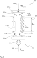
- Fig. 3 illustrates an exploded view of the suspension assembly 3a under static conditions (i.e. where the acceleration of the vehicle is zero).
- the corner force 16a may be equal to the corner weight W corner (i.e. the portion of the TVW supported by suspension assembly 3a).
- the other suspension assemblies may also support equal or approximately equal corner weights such that the sum of all the corner weights may be equal to the TVW.
- the W corner is supported by damper force 20a F D and spring force 20b F S .
- the damping-element 11a and spring-element 10a also simultaneously apply forces 21a and 21b on the wheel assembly that are equal in magnitude to 20a and 20b respectively.
- the road reaction force 22 (F road ) applied by the road surface is equal to and resists the sum of forces 21a and 21b plus the weight of the unsprung mass. Under these conditions, the spring-element is compressed by a force 20b (which is equal to 21b ) resulting in a compressed length 19 (Lc) of the spring-element.
- Equation 1 is sometimes referred to as Hooke's Law.
- the equilibrium static forces shown in Fig. 3 may be disturbed by, for example, acceleration of the vehicle and/or the wheel assembly in one or more directions.
- the equilibrium may also be disturbed if the wheel 23a becomes airborne, e.g. while traversing a pothole.
- ⁇ F M US ⁇ a US
- ⁇ F the net force on the wheel assembly (i.e. the sum of the unbalanced forces)
- Mus the mass of the unsprung mass
- a US the acceleration of the unsprung mass.
- Fig. 4 illustrates a condition of the suspension assembly 3a where the force applied by the ground is absent or effectively absent, for example, as a result of the wheel 23a becoming airborne.
- the wheel 23a becomes airborne, there may be three forces that act on the unsprung mass (Mus): (1) the spring-element force F S , 41b, (2) the damping-element force F D 41a, and (3) the weight of the wheel assembly W WA 41c. If these forces are not in balance, the wheel assembly shown in the embodiment of Fig. 4 may begin to accelerate, relative to the vehicle body (not shown).
- the force applied by the damping-element F D to the wheel assembly 5a may initially (i.e. when the wheel assembly becomes airborne) be directed away from the vehicle body (i.e. downward) because of the pre-charge pressure.
- the force applied by the damping-element may reverse direction and become a resisting force to this motion.
- This resisting force may be proportional to the product of the damping coefficient of the damping-element and the velocity of the wheel assembly relative to the vehicle body. If the damping-element shown in Fig.
- the force F D may be, for example, a resisting force, an active-compression force, or an active-extension force.
- the force may be applied, for example, from the instant that the wheel 23a becomes airborne, after that point in time, or even prior to the wheel becoming airborne as commanded by one or more controllers of the active suspension actuator.
- the magnitude and/or the timing of the force applied by the actuator may be commanded by a controller based on a prediction of the position of the wheel 23a relative to a pothole at the given speed of the vehicle.
- This prediction may be determined at least partly based on information from various sensors, for example, forward looking sensors such as LiDAR, radar, acoustic transducers and/or cameras.
- the prediction may be at least partially based on localization algorithms and/or map data from, for example, a digital remote or local (i.e. stored onboard the vehicle) map, GPS, terrain based localization data, data collected a leading wheel assembly of the vehicle to be used by a controller controlling, for example, a suspension actuator of a trailing wheel assembly, etc.
- the spring-element 10a When the vehicle is supported by, for example, a road surface or another surface, the spring-element 10a may be compressed sufficiently to support the corner weight of the vehicle, either unaided or in conjunction with the precharge force applied by the damping element. As soon as the wheel becomes airborne, F S , applied by the spring-element and the weight of the wheel assembly 5a, may cause the wheel assembly to accelerate downward. Concurrently, the damper element may apply a retarding force on the wheel assembly.
- the damper force, F D may be a function of the product of the velocity of the wheel assembly relative to the vehicle body and the damping coefficient of the damper element.
- the damping coefficient may be a constant, while in the case of a semi-active damper, the damping coefficient may be a variable quantity, in an operating range determined by a controller.
- the damping-element is an active suspension actuator, it may be used to apply a force on the wheel assembly 5a that may at least partially or fully counter the force applied by the spring-element at any given position of the wheel assembly relative to the vehicle body. If the force capacity of the actuator is sufficient, the suspension actuator may be used to hold the wheel assembly in-place relative to the vehicle body or to even move it closer to the vehicle body (i.e. compress the suspension assembly).
- the wheel assembly may accelerate away from the vehicle body at a rate that is proportional to the unbalanced force though this rate of acceleration may be less that it would be in the absence of the force applied by the damping-element.
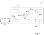
- Fig. 5 illustrates the top view of a vehicle 1 approaching a pothole 41 that is L P meters long in the direction of travel of the vehicle.
- the vehicle may have four wheels: front left wheel 23a, front right wheel 23b, rear right wheel 23c, and rear left wheel 23d.
- Axis 45a connects the center of the contact patch of the front right wheel and the center of the contact patch of diagonally opposed rear left wheel.
- Axis 45b connects the center of the contact patch of the left front tire and the center of the contact patch of the diagonally opposed right rear tire.
- Intersection point 44 is the intersection of axis 45a and axis 45b and point 43 is the top view of the center-of-gravity of the vehicle 1.
- the center-of-gravity 43 is located in front of intersection point 44.
- the center of gravity may be located in other positions relative to point 44 as determined by the mass distribution of the vehicle, the occupants, and the cargo carried by the vehicle, as the disclosure is not so limited.
- wheel 23a may enter the pothole 41 while wheels 23b, 23c, and 23d remain on a road surface.
- wheel 23d may enter the pothole 41 while wheels 23b, 23c, and 23a remain on a road surface.
- the front left wheel 23a and rear left wheel may enter the pothole sequentially as the vehicle travels past the pothole.
- the road-reaction forces on all four tires may be affected.
- the reaction to the TVW, acting on the center of gravity 43 may be borne by one or more of the other three wheels.
- the TVW of the vehicle acting on the center of gravity 43 may induce a moment about axis 45a equal to the weight of the vehicle multiplied by the moment arm 43a.
- a compressive force may be applied to suspension assembly 3d (shown in Fig. 1 ), for example by using a suspension actuator, to reduce or cancel the effect of the force applied by spring element 10d.
- the compressive force applied by the suspension actuator may oppose an extension force applied by the associated spring which will reduce a net load applied to the wheel by the combined forces applied to the wheel by the spring and suspension actuator of the suspension assembly 3d.
- the wheel at the opposing corner may be partially unloaded or fully unloaded. In either case, by reducing a force applied to the wheel assembly at the corner diametrically opposite a corner where a wheel is traversing a pothole, the unbalanced moment applied to the vehicle may be reduced which may reduce the movement of the wheel into the pothole as the wheel traverses the pothole.
- suspension assembly 3b and/or suspension assembly 3c one or more suspension actuators that may be included in suspension assemblies 3b and 3c may be used to maintain the ride height of the vehicle by increasing the magnitude of the extension force interposed between the corresponding wheel assemblies and the vehicle body (sprung mass) to accommodate the portion of the TVW that has been offloaded from the other suspension assemblies.
- suspension actuators may be used to raise the ride height or lower the ride height depending on the magnitude of the extension forces applied by the suspension actuators of the noted suspension assemblies.
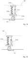
- Figs. 6-9 illustrate various degrees of extension and compression of the suspension assembly of Fig. 2 .
- no forces are applied to the spring element by the rest of the assembly (shown as a ghost view). Under these conditions, the spring-element may assume its free length L F 50.
- Fig. 7 the suspension assembly is shown with only static forces present (i.e. no acceleration) where the spring element is at its static length Ls 51.
- the spring element 10a and the pre-charge force applied by the damper element 11a support the front left corner weight of the vehicle.
- the spring element 8 and 9 show the spring element in an extended state and a compressed state respectively.
- the spring element may be extended by the application of an extension force or compressed by the application of a compression force. Such forces may result from dynamic forces acting on the vehicle body and/or due to forces applied by an active suspension actuator.
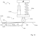
- Fig. 10 illustrates an operating condition where wheel 23a, of suspension assembly 3a, may become airborne (i.e. unsupported by the road surface, the ground or any other surface) while traversing, for example, a pothole or other discontinuity in a road surface 61a.
- the wheel may descend into, for example, a pothole by following trajectories such as, for example, 63a, 63b, 63c, 63d.
- the trajectory followed may depend on, for example, the net force on the wheel assembly (including its weight) and the mass of the wheel assembly.
- the extent to which the wheel descends into the pothole will also depend on the speed of the vehicle and the length of the discontinuity along the direction of travel which may determine the length of the period during which the wheel remains airborne.
- the extent to which the wheel penetrates into the pothole may be limited or eliminated by a locking mechanism such as, for example, the locking system described below.
- the beginning-of-pothole road surface elevation 61a is shown to be equal to the end-of-pothole road surface elevation of road surface 61b.
- the end-of-pothole road surface elevation may be higher (road surface 61c ) or lower (road surface 61d ) than the beginning-of-pothole road surface elevation 61a.
- the mismatch distance between the wheel 23a contact patch position at the end of the pothole (shown as a ghost view) 69b, 69c, and 69d may, at least, partly be a function of the end-of-pothole road surface elevation 61b, 61c, and 61d.
- a pothole may have a floor 65 that is at a lower elevation than both the beginning-of-pothole elevation and the end-of-pothole road surface elevation.
- a pothole may also include near-wall 64 and/or an end-wall 63, see Fig. 10 .
- the embodiment of a suspension system in Fig. 10 traversing a pothole may be operated under exemplary, non-limiting conditions detailed in Table I below: Table I: Exemplary operating conditions Vehicle Mass (M S ) 2,500 kg Unsprung Mass (M US ) 50 kg Spring Rate 25 N/mm Pothole Length (L P ) 0.8 m Vehicle Speed 40 mph Vehicle Size 1.9m x 4.8m MOI 850 kg m 2 where MOI is the moment of inertia of the sprung mass about axis 45a shown in Fig. 5 .
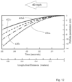
- Fig. 12 shows the trajectory of wheel 23a of Fig. 10 , from the point when it becomes airborne, as function of the compression-force applied by the damping element 11a.
- Table II shows the compression-force for each trajectory in Fig. 11 .
- Table II Relationship between end pothole penetration and restraining force of the suspension actuator Trajectory Compression Force (N) End Pothole Penetration (cm) 62a 0 -12 62b 2000 -9 62c 3000 -7 62d 4000 -5
- N Trajectory Compression Force
- cm End Pothole Penetration
- Fig. 13 illustrates a condition where the there is sufficient intrusion into the pothole such that the wheel strikes the end-wall of the pothole. Striking the end-wall may cause damage to, for example, the wheel, tire and/or one or more suspension components.
- the distance 70 represents how far the wheel has dropped below the top of the end-wall (or the end-of-pothole road surface elevation). The distance X may be equal to the sum of the amount of extension of spring element and a degree to which the corner of the vehicle dips towards the pothole due to the unbalanced moment applied to the vehicle when the wheel becomes airborne.
- the vehicle may rotate about axis 55a in Fig. 5 as a result of the weight of the vehicle effectively acting on the center of gravity 53 and or an unbalanced force applied by spring element 11c. It is noted that the rotation about axis 55a may be greater if the wheel 23a is prevented from accelerating, or if the magnitude of the acceleration is diminished by applying a compression force with the active suspension actuator.
- the attachment device 5a may drop by an amount Y 71.
- the distance X depends partly on the length of time the wheel remains airborne which may depend on, for example, the length of the pothole "d", and the velocity of the vehicle.
- the mass of the wheel assembly and the forces applied by the spring element and the damper element may also affect the distance X. It is noted that the longer the pothole (length d) and the slower the speed of the vehicle, the further the wheel may drop into the pothole and the more severe the collision with the end-wall of the pothole.
- Fig. 14 illustrates an operating condition where the active suspension actuator is used to apply an extension force to extend the suspension assembly so that wheel 23a may travel along the floor of the pothole instead of becoming airborne.
- the elevation 90 of the vehicle may be maintained by the suspension assembly despite the presence of the pothole.
- the wheel 23a may strike the end-wall of pothole 41.
- Fig. 16 depicts an embodiment of an active suspension actuator 99a.
- Housing 100a includes a piston 101a, piston rod 16a, fluid filled compression volume 102a, and fluid filled extension volume 103a.
- the hydraulic circuit of Fig. 16 includes pressurized fluid reservoir 104a in fluid communication with the compression volume and fluid reservoir 105a in fluid communication with the extension volume. In some embodiments, these reservoirs are at least partially filled with, for example, air or other compressible medium.
- One port of a bi-directional hydraulic pump/motor 106a is in fluid communication with the compression volume 102a and a second port is in fluid communication with the extension volume 103a.
- the bi-directional hydraulic pump/motor may be a hydraulic motor that may be operated as a hydraulic pump or a hydraulic pump that may be operated as a hydraulic motor.
- valve assembly 107a may be used to control fluid flow out of and/or into the extension volume.
- valve assembly may include a two-position controlled valve 108a that in a first position allows free, or effectively free, bidirectional fluid flow to and from the extension volume, while in the second position it hydraulically locks the extension volume preventing fluid from leaving the extension volume and the active suspension actuator from undergoing extension.
- check valve 109a may be used to allow unidirectional, unrestricted or effectively unrestricted flow into the extension volume.
- the check valve 109a may be configured to prevent cavitation in the extension volume in the event of rapid compression of the suspension actuator. Such rapid compression may occur, for example, when the wheel makes contact with the road surface after being airborne for a period while traversing a pothole.
- a bypass control system 110a may be used to allow fluid exchange between the extension volume and the compression volume that bypasses the hydraulic pump/motor such that fluid flows between the extension volume and the compression volume without passing through the hydraulic pump/motor.
- the bypass control system may include one or more valves that may include one or more controlled valves.
- the hydraulic pump/motor may be used to actively control the motion of piston 101a.
- a flow restriction 111a may be interposed between the reservoir 105a and the hydraulic circuit. The restriction may act as a low pass filter that restricts the flow of fluid into and out of the reservoir at higher frequencies.
- Fig. 17 shows a block diagram of an embodiment of an exemplary control system 120 for controlling one or more damping element(s) 121 of a suspension assembly of a vehicle (not shown).
- the damping element may be, for example, a semi-active damper or an active suspension actuator.
- the controller 122 may receive information from one or more sources of information including, for example: (i) a network 123, such as a wireless network, (ii) a GPS receiver 124, (iii) localization algorithm 125, (iv) a leading wheel assembly sensor 126, (v) electronic data storage device such as computer memory or a disk drive, (vi) one or more preview sensor(s) 128 (e.g., LiDAR, radar, ultrasonic transducer, video camera) and vehicle sensor(s) 128a that measure one or more vehicle state parameters.
- the controller may also exchange information with one or more secondary controller(s) 129 in the vehicle.
- the controller may use data from one or more sources to determine, for example, the position of a pothole relative to the vehicle, the size of the pothole, the depth of the pothole, and speed of the vehicle.
- the controller may also collect information about the likelihood of avoiding the pothole. The controller may then determine a strategy for traversing.
- the controller may adjust the operation of one or more damping elements. For example, based on the information collected, the controller may elect to traverse a pothole while the wheel is airborne or traverse a pothole by entering it and traveling along the floor of the pothole.
- the controller 122 may adjust the damping coefficient of one or more semi-active damping elements or suspension actuator in various suspension subassemblies. Alternatively or additionally, the controller may elect to activate one or more hydraulic lock mechanisms.
- the controller may activate an active suspension actuator to extend the wheel so it travels along the floor of the pothole. Additionally the controller may increase the compression force when the wheel reaches the end-wall of the pothole to facilitate the extraction of the wheel from the pothole.
- the controller may directly, or by communicating with at least one other controller, alter the operation of at least one other suspension assembly.
- the controller controlling the operation of a left front wheel of a vehicle may identify a pothole, determine its relative position, its size, and the speed of the vehicle. The controller may further elect to traverse the pothole while the wheel is airborne. The controller may determine that the left front wheel may strike the end-wall of the pothole with a certain mismatch.
- the controller may directly or by communicating with at least one additional controller, operate at least one additional controller to raise at least a portion of the vehicle to reduce the projected mismatch between the left front wheel and the end-of-pothole road surface elevation.
- the controller may cause the right front and left rear of the vehicle to be raised by an amount that is equal to or greater than the mismatch amount. Additionally or alternatively the controller may cause the actuator controller of the right rear suspension assembly to apply a compressive force on the spring element or to lock the right rear wheel assembly in place relative to the vehicle body while the right front wheel is airborne. It is noted that the vehicle may be an autonomous or driven vehicle.
- a vehicle may include a suspension assembly associated with each of four corners of the vehicle, such as the vehicle illustrated in Fig. 1 .
- Each suspension assembly may support a portion of the TVW by applying a net force on the vehicle.
- Each suspension assembly may include an active suspension actuator that may be used to modify the net force being applied by each suspension assembly.
- a controller may be used to alter the operation of an active suspension actuator in one or more of the other suspension assemblies to change the net force being applied by one or more of those other suspension assemblies.
- the actuator net force applied by suspension assembly 3b and/or suspension assembly 3c located at adjacent corners to the first corner may be increased.
- the forces applied by suspension assembly 3c and/or 3d may be increased before or after the first wheel 23a becomes airborne.
- a controller may also alter the operation of an active suspension actuator in the first suspension assembly associated with the first corner (e.g. 3a ).
- the associated actuator may be used to, for example, apply a compressive force on the associated spring element (e.g. 1a .) to reduce or eliminate the penetration of the first wheel into the pothole.
- the actuator in the suspension assembly at the corner opposite the first corner may also be used to apply a compressive force on the associated spring element to mitigate or eliminate a roll moment induced by the spring element associated with the spring assembly at the fourth corner (e.g. spring element 3d ).
- a controller may be understood to refer to one or more processors operatively coupled with associated memory which may be a non-transitory computer readable medium.
- the memory may include computer readable instructions that when executed by the one or more processors operate the suspension systems, sensors, and other components described herein to perform any of the disclosed methods in any appropriate combination.
Landscapes
- Engineering & Computer Science (AREA)
- Mechanical Engineering (AREA)
- Vehicle Body Suspensions (AREA)
Applications Claiming Priority (3)
| Application Number | Priority Date | Filing Date | Title |
|---|---|---|---|
| US201862747811P | 2018-10-19 | 2018-10-19 | |
| PCT/US2019/057006 WO2020081980A1 (en) | 2018-10-19 | 2019-10-18 | Method and apparatus for responding to road surface discontinuities |
| EP19872724.0A EP3867088B1 (de) | 2018-10-19 | 2019-10-18 | Verfahren zur steuerung einer aktiven radaufhängung |
Related Parent Applications (1)
| Application Number | Title | Priority Date | Filing Date |
|---|---|---|---|
| EP19872724.0A Division EP3867088B1 (de) | 2018-10-19 | 2019-10-18 | Verfahren zur steuerung einer aktiven radaufhängung |
Publications (2)
| Publication Number | Publication Date |
|---|---|
| EP4497614A2 true EP4497614A2 (de) | 2025-01-29 |
| EP4497614A3 EP4497614A3 (de) | 2025-07-30 |
Family
ID=70284124
Family Applications (2)
| Application Number | Title | Priority Date | Filing Date |
|---|---|---|---|
| EP24195845.3A Pending EP4497614A3 (de) | 2018-10-19 | 2019-10-18 | Verfahren und vorrichtung zur reaktion auf strassenoberflächendiskontinuitäten |
| EP19872724.0A Active EP3867088B1 (de) | 2018-10-19 | 2019-10-18 | Verfahren zur steuerung einer aktiven radaufhängung |
Family Applications After (1)
| Application Number | Title | Priority Date | Filing Date |
|---|---|---|---|
| EP19872724.0A Active EP3867088B1 (de) | 2018-10-19 | 2019-10-18 | Verfahren zur steuerung einer aktiven radaufhängung |
Country Status (4)
| Country | Link |
|---|---|
| US (2) | US11724555B2 (de) |
| EP (2) | EP4497614A3 (de) |
| JP (2) | JP2022504463A (de) |
| WO (1) | WO2020081980A1 (de) |
Families Citing this family (14)
| Publication number | Priority date | Publication date | Assignee | Title |
|---|---|---|---|---|
| US10901432B2 (en) | 2017-09-13 | 2021-01-26 | ClearMotion, Inc. | Road surface-based vehicle control |
| EP4497614A3 (de) | 2018-10-19 | 2025-07-30 | Clearmotion, Inc. | Verfahren und vorrichtung zur reaktion auf strassenoberflächendiskontinuitäten |
| US11801726B2 (en) | 2018-11-01 | 2023-10-31 | ClearMotion, Inc. | Vehicle control based on localization and road data |
| EP3942382B1 (de) | 2019-03-19 | 2026-02-25 | ClearMotion, Inc. | Fahrzeuglokalisierungssystem, verfahren und steuerungen |
| GB2597460B (en) * | 2020-07-21 | 2023-03-29 | Jaguar Land Rover Ltd | Vehicle active suspension control system and method |
| US12474487B2 (en) | 2020-09-17 | 2025-11-18 | ClearMotion, Inc. | Methods and systems for terrain-based localization of a vehicle |
| WO2022093847A1 (en) | 2020-10-27 | 2022-05-05 | Clearmotion,Inc. | Systems and methods for vehicle control using terrain-based localization |
| US11932072B2 (en) * | 2021-03-08 | 2024-03-19 | DRiV Automotive Inc. | Suspension control system and method with event detection based on unsprung mass acceleration data and pre-emptive road data |
| JP7178440B2 (ja) * | 2021-03-22 | 2022-11-25 | 本田技研工業株式会社 | 車両 |
| CN113370734B (zh) * | 2021-06-26 | 2022-02-11 | 燕山大学 | 基于车前地形的主动悬挂惯性调控方法和控制系统 |
| CN115139722A (zh) * | 2022-09-06 | 2022-10-04 | 万向钱潮股份公司 | 车辆运行调整方法、装置、行驶车、电子设备及存储介质 |
| CN120225409A (zh) * | 2022-10-18 | 2025-06-27 | 动态清晰公司 | 用于控制车辆与路面之间相互作用的系统和方法 |
| US20240181831A1 (en) * | 2022-12-05 | 2024-06-06 | Fca Us Llc | Suspension based active force damping for a vehicle |
| WO2026064265A1 (en) * | 2024-09-19 | 2026-03-26 | Advanced Suspension Technology Llc | Active suspension system |
Family Cites Families (60)
| Publication number | Priority date | Publication date | Assignee | Title |
|---|---|---|---|---|
| JP2001191778A (ja) * | 2000-01-11 | 2001-07-17 | Yamaha Motor Co Ltd | 四輪車用懸架装置 |
| US7641181B2 (en) * | 2003-01-24 | 2010-01-05 | Liquid Spring Technologies, Inc. | Distributed power suspension system |
| JP2004322956A (ja) * | 2003-04-28 | 2004-11-18 | Tcm Corp | コンテナキャリアのサスペンション |
| JP2005300294A (ja) * | 2004-04-09 | 2005-10-27 | Denso Corp | 道路形状検出装置および道路形状検出方法 |
| JP2006027522A (ja) * | 2004-07-20 | 2006-02-02 | Tcm Corp | コンテナキャリア |
| US7334801B2 (en) * | 2005-01-28 | 2008-02-26 | Hohmann Michael F | Automated vehicle suspension system |
| DE102006039353A1 (de) * | 2006-08-22 | 2008-03-06 | Daimler Ag | Vorrichtung und Verfahren zur Beeinflussung der Federkraftcharakteristik eines aktiven Fahrwerks eines Kraftfahrzeugs |
| US8285447B2 (en) | 2007-03-20 | 2012-10-09 | Enpulz, L.L.C. | Look ahead vehicle suspension system |
| DE102007046040A1 (de) | 2007-09-26 | 2009-04-30 | Benjamin Struss | Aktive Kraftfahrzeugradaufhängungsvorrichtung |
| KR20110026433A (ko) | 2008-06-25 | 2011-03-15 | 톰톰 인터내셔날 비.브이. | 주차시설 찾기를 탐지하는 내비게이션 장치 및 방법 |
| DE102008032545A1 (de) | 2008-07-10 | 2010-01-14 | Daimler Ag | Beeinflussungsvorrichtung zur Beeinflussung eines Stellers eines aktiven Stabilisators |
| DE102008034908A1 (de) | 2008-07-26 | 2009-03-12 | Daimler Ag | Verfahren zur Stabilisierung eines Fahrzeuges bei Aquaplaning |
| JP5463263B2 (ja) * | 2009-11-30 | 2014-04-09 | 日立オートモティブシステムズ株式会社 | 車両用サスペンション制御装置 |
| DE102010033729B4 (de) | 2010-08-07 | 2014-05-08 | Audi Ag | Verfahren und Vorrichtung zum Bestimmen der Position eines Fahrzeugs auf einer Fahrbahn sowie Kraftwagen mit einer solchen Vorrichtung |
| JP2014531357A (ja) * | 2011-09-06 | 2014-11-27 | ジャガー ランド ローバー リミテッドJaguar Land Rover Limited | サスペンション制御装置 |
| CN103826887A (zh) * | 2011-09-27 | 2014-05-28 | 爱信精机株式会社 | 悬架系统 |
| WO2013111500A1 (ja) * | 2012-01-26 | 2013-08-01 | 日産自動車株式会社 | 車両の制御装置 |
| US9738132B2 (en) * | 2012-06-25 | 2017-08-22 | Ford Global Technologies, Llc | Ride performance optimization in an active suspension system |
| DE102012015492B4 (de) | 2012-08-04 | 2016-05-12 | Audi Ag | Verfahren und Vorrichtung zum Betreiben eines Fahrwerks |
| DE102012024086B4 (de) | 2012-12-07 | 2016-05-19 | Audi Ag | Verfahren zum Betreiben eines Kraftfahrzeugs |
| US8788146B1 (en) * | 2013-01-08 | 2014-07-22 | Ford Global Technologies, Llc | Adaptive active suspension system with road preview |
| US9702349B2 (en) * | 2013-03-15 | 2017-07-11 | ClearMotion, Inc. | Active vehicle suspension system |
| DE102014204519A1 (de) | 2013-04-08 | 2014-10-09 | Ford Global Technologies, Llc | Vorrichtung und Verfahren zur proaktiven Steuerung eines Schwingungsdämpfungssystems eines Fahrzeugs |
| US9409459B2 (en) * | 2013-07-19 | 2016-08-09 | Papé Machinery, Inc. | 4-way leveling |
| TWI507307B (zh) * | 2013-08-23 | 2015-11-11 | Nat Univ Tsing Hua | 路面粗糙度輪廓之即時建立裝置及其用於主動式車輛懸吊系統控制之方法 |
| JP2015147486A (ja) * | 2014-02-06 | 2015-08-20 | 小林 正和 | サスペンション制御システム及び車両 |
| CN106414121B (zh) * | 2014-05-22 | 2019-11-22 | 威伯科有限公司 | 用于对空气悬挂式机动车辆进行水平调节的方法 |
| JP6510796B2 (ja) * | 2014-11-07 | 2019-05-08 | Kyb株式会社 | サスペンション装置およびサスペンション制御装置 |
| DE102014223475B4 (de) | 2014-11-18 | 2022-04-21 | Zf Friedrichshafen Ag | Verfahren zum Betreiben eines aktiven Fahrwerksystems eines Kraftfahrzeuges |
| US9669677B2 (en) * | 2015-05-28 | 2017-06-06 | Ford Global Technologies, Llc | Vehicle active suspension system and method of control |
| CN108139456B (zh) | 2015-08-20 | 2022-03-04 | 泽安驾驶公司 | 加速度计辅助导航的方法 |
| US10293653B2 (en) * | 2015-09-29 | 2019-05-21 | Ford Global Technologies, Llc | Obstacle avoidance system with active suspensions |
| JP6956722B2 (ja) * | 2015-12-24 | 2021-11-02 | クリアモーション,インコーポレイテッド | 統合多重アクチュエータ電子油圧ユニット |
| US10828954B2 (en) | 2016-07-13 | 2020-11-10 | Ford Global Technologies, Llc | Ride performance optimization systems and devices, and related methods |
| US20180079272A1 (en) | 2016-09-20 | 2018-03-22 | Apple Inc. | Motion minimization systems and methods |
| WO2018148689A1 (en) * | 2017-02-12 | 2018-08-16 | ClearMotion, Inc. | Hydraulic actuator a frequency dependent relative pressure ratio |
| US10486485B1 (en) | 2017-04-19 | 2019-11-26 | Zoox, Inc. | Perception based suspension control |
| WO2018234055A1 (en) | 2017-06-20 | 2018-12-27 | Nira Dynamics Ab | Road conditition monitoring |
| EP3682417B1 (de) | 2017-09-10 | 2024-01-10 | Tactile Mobility Ltd. | Verfahren und vorrichtung zur gewichtsermittlung eines fahrzeugs |
| US10901432B2 (en) | 2017-09-13 | 2021-01-26 | ClearMotion, Inc. | Road surface-based vehicle control |
| US11392127B2 (en) | 2018-10-15 | 2022-07-19 | Zoox, Inc. | Trajectory initialization |
| EP4497614A3 (de) | 2018-10-19 | 2025-07-30 | Clearmotion, Inc. | Verfahren und vorrichtung zur reaktion auf strassenoberflächendiskontinuitäten |
| JP2022505326A (ja) * | 2018-10-19 | 2022-01-14 | クリアモーション,インコーポレイテッド | サスペンションシステムを動作させるための方法及び装置 |
| US11801726B2 (en) | 2018-11-01 | 2023-10-31 | ClearMotion, Inc. | Vehicle control based on localization and road data |
| US11110922B2 (en) | 2018-11-05 | 2021-09-07 | Zoox, Inc. | Vehicle trajectory modification for following |
| US12530970B2 (en) | 2018-12-26 | 2026-01-20 | Zoox, Inc. | Collision avoidance system |
| EP3942382B1 (de) | 2019-03-19 | 2026-02-25 | ClearMotion, Inc. | Fahrzeuglokalisierungssystem, verfahren und steuerungen |
| US20220203801A1 (en) * | 2019-05-22 | 2022-06-30 | Mario Rolando NAVARRETE | Land vehicle |
| WO2021091909A1 (en) | 2019-11-04 | 2021-05-14 | ClearMotion, Inc. | Vehicle system control based on road feature detection and classification |
| CN114761758A (zh) | 2019-11-04 | 2022-07-15 | 动态清晰公司 | 多车道道路表征和跟踪算法 |
| WO2021138431A1 (en) | 2019-12-30 | 2021-07-08 | ClearMotion, Inc. | Proactive control of vehicle systems |
| US12474487B2 (en) | 2020-09-17 | 2025-11-18 | ClearMotion, Inc. | Methods and systems for terrain-based localization of a vehicle |
| WO2022093847A1 (en) | 2020-10-27 | 2022-05-05 | Clearmotion,Inc. | Systems and methods for vehicle control using terrain-based localization |
| US20220324421A1 (en) | 2020-12-23 | 2022-10-13 | ClearMotion, Inc. | Systems and methods for terrain-based insights for advanced driver assistance systems |
| WO2022139933A1 (en) | 2020-12-23 | 2022-06-30 | ClearMotion, Inc. | Vehicle localization systems and methods |
| WO2022140657A1 (en) | 2020-12-23 | 2022-06-30 | Clearmotion,Inc. | Systems and methods for vehicle control using terrain-based localization |
| US11754471B1 (en) * | 2021-04-30 | 2023-09-12 | Zoox, Inc. | Techniques for testing a deflection of a structural section of a vehicle |
| US11879518B2 (en) * | 2022-01-05 | 2024-01-23 | Ford Global Technologies, Llc | Suspension system with improved articulation |
| CN117301784A (zh) * | 2022-06-24 | 2023-12-29 | 长城汽车股份有限公司 | 一种车身高度控制的方法、装置、存储介质及车辆 |
| US11753024B1 (en) * | 2022-07-15 | 2023-09-12 | Ghost Autonomy Inc. | Anticipatory vehicle headlight actuation |
-
2019
- 2019-10-18 EP EP24195845.3A patent/EP4497614A3/de active Pending
- 2019-10-18 WO PCT/US2019/057006 patent/WO2020081980A1/en not_active Ceased
- 2019-10-18 JP JP2021519133A patent/JP2022504463A/ja active Pending
- 2019-10-18 EP EP19872724.0A patent/EP3867088B1/de active Active
- 2019-10-18 US US17/285,174 patent/US11724555B2/en active Active
-
2023
- 2023-06-28 US US18/343,130 patent/US12447791B2/en active Active
-
2025
- 2025-09-04 JP JP2025146801A patent/JP2025183278A/ja active Pending
Also Published As
| Publication number | Publication date |
|---|---|
| JP2025183278A (ja) | 2025-12-16 |
| EP4497614A3 (de) | 2025-07-30 |
| EP3867088B1 (de) | 2024-08-28 |
| US11724555B2 (en) | 2023-08-15 |
| US12447791B2 (en) | 2025-10-21 |
| EP3867088A1 (de) | 2021-08-25 |
| WO2020081980A1 (en) | 2020-04-23 |
| EP3867088A4 (de) | 2022-07-20 |
| US20210394573A1 (en) | 2021-12-23 |
| JP2022504463A (ja) | 2022-01-13 |
| US20240100900A1 (en) | 2024-03-28 |
Similar Documents
| Publication | Publication Date | Title |
|---|---|---|
| US12447791B2 (en) | Method and apparatus for responding to road surface discontinuities | |
| DE10327593B4 (de) | System und Verfahren zum Bestimmen der Lage eines Kraftfahrzeuges | |
| US11541797B2 (en) | Systems and methods for minimizing motion sickness in vehicles | |
| DE112018007347B4 (de) | Aufhängungssteuereinrichtung | |
| US3124368A (en) | Electronic controlled vehicle suspension system | |
| US9321320B2 (en) | Ride performance optimization in an active suspension system | |
| EP0318713B1 (de) | System zur Regelung einer Fahrzeugaufhängung | |
| US9738132B2 (en) | Ride performance optimization in an active suspension system | |
| DE69131595T2 (de) | Verfahren und gerät zur dynamischen niveauregulierung | |
| EP2910468B1 (de) | Aktiver Fahrwerksdämpfer | |
| US5765115A (en) | Pneumatic tilt stabilization suspension system | |
| CN108698464A (zh) | 用于控制主动悬架系统的阻尼器的系统和方法 | |
| SE532590C2 (sv) | Fjädringsanordning samt förfarande vid fjädring och/eller dämpning för fordon | |
| DE102021113136A1 (de) | Dämpfungssteuervorrichtung und dämpfungssteuerverfahren | |
| WO2009055841A1 (en) | Stability control for a vehicle | |
| JP2022072373A (ja) | 車両の制御方法及び制御装置 | |
| DE102021116116B4 (de) | Dämpfungssteuervorrichtung und Dämpfungssteuerverfahren für Fahrzeuge | |
| US9950585B2 (en) | Method for providing a manipulated variable | |
| WO2021138431A1 (en) | Proactive control of vehicle systems | |
| JP2011020638A (ja) | 車両振動抑制装置 | |
| JP4648055B2 (ja) | 車両における可変減衰力ダンパーの制御装置 | |
| DE102017111107B4 (de) | Verfahren und Vorrichtung zum Anpassen eines Fahrwerkes bei einem Kraftfahrzeug | |
| JP3052995B2 (ja) | サスペンション制御装置 | |
| DE102015208336A1 (de) | Verfahren zum Steuern einer Einfederbewegung einer Radaufhängung | |
| US20250229590A1 (en) | Suspension damping force control system and method |
Legal Events
| Date | Code | Title | Description |
|---|---|---|---|
| PUAI | Public reference made under article 153(3) epc to a published international application that has entered the european phase |
Free format text: ORIGINAL CODE: 0009012 |
|
| STAA | Information on the status of an ep patent application or granted ep patent |
Free format text: STATUS: THE APPLICATION HAS BEEN PUBLISHED |
|
| AC | Divisional application: reference to earlier application |
Ref document number: 3867088 Country of ref document: EP Kind code of ref document: P |
|
| AK | Designated contracting states |
Kind code of ref document: A2 Designated state(s): AL AT BE BG CH CY CZ DE DK EE ES FI FR GB GR HR HU IE IS IT LI LT LU LV MC MK MT NL NO PL PT RO RS SE SI SK SM TR |
|
| REG | Reference to a national code |
Ref country code: DE Ref legal event code: R079 Free format text: PREVIOUS MAIN CLASS: B60G0017016500 Ipc: B60G0017020000 |
|
| PUAL | Search report despatched |
Free format text: ORIGINAL CODE: 0009013 |
|
| AK | Designated contracting states |
Kind code of ref document: A3 Designated state(s): AL AT BE BG CH CY CZ DE DK EE ES FI FR GB GR HR HU IE IS IT LI LT LU LV MC MK MT NL NO PL PT RO RS SE SI SK SM TR |
|
| RIC1 | Information provided on ipc code assigned before grant |
Ipc: B60G 17/033 20060101ALI20250625BHEP Ipc: B60G 17/04 20060101ALI20250625BHEP Ipc: B60G 17/018 20060101ALI20250625BHEP Ipc: B60G 17/019 20060101ALI20250625BHEP Ipc: B60G 17/0195 20060101ALI20250625BHEP Ipc: B60G 17/08 20060101ALI20250625BHEP Ipc: B60G 17/0165 20060101ALI20250625BHEP Ipc: B60G 17/02 20060101AFI20250625BHEP Ipc: B60G 17/027 20060101ALI20250625BHEP |
|
| RAP3 | Party data changed (applicant data changed or rights of an application transferred) |
Owner name: CLEARMOTION, INC. |
|
| STAA | Information on the status of an ep patent application or granted ep patent |
Free format text: STATUS: REQUEST FOR EXAMINATION WAS MADE |
|
| 17P | Request for examination filed |
Effective date: 20260129 |