EP4497719A1 - Système de fonctionnement à distance - Google Patents
Système de fonctionnement à distance Download PDFInfo
- Publication number
- EP4497719A1 EP4497719A1 EP23774363.8A EP23774363A EP4497719A1 EP 4497719 A1 EP4497719 A1 EP 4497719A1 EP 23774363 A EP23774363 A EP 23774363A EP 4497719 A1 EP4497719 A1 EP 4497719A1
- Authority
- EP
- European Patent Office
- Prior art keywords
- movement
- moving object
- mode
- remote
- controller
- Prior art date
- Legal status (The legal status is an assumption and is not a legal conclusion. Google has not performed a legal analysis and makes no representation as to the accuracy of the status listed.)
- Pending
Links
Images





Classifications
-
- B—PERFORMING OPERATIONS; TRANSPORTING
- B66—HOISTING; LIFTING; HAULING
- B66C—CRANES; LOAD-ENGAGING ELEMENTS OR DEVICES FOR CRANES, CAPSTANS, WINCHES, OR TACKLES
- B66C13/00—Other constructional features or details
- B66C13/18—Control systems or devices
- B66C13/40—Applications of devices for transmitting control pulses; Applications of remote control devices
-
- B—PERFORMING OPERATIONS; TRANSPORTING
- B66—HOISTING; LIFTING; HAULING
- B66C—CRANES; LOAD-ENGAGING ELEMENTS OR DEVICES FOR CRANES, CAPSTANS, WINCHES, OR TACKLES
- B66C13/00—Other constructional features or details
- B66C13/18—Control systems or devices
- B66C13/46—Position indicators for suspended loads or for crane elements
Definitions
- the present invention relates to a technique for remotely controlling the movement of a moving object by wire or wireless.
- overhead cranes are used to transport heavy objects.
- the overhead crane transports the suspended load by moving the hoist, trolley, and other lifting devices for suspending the suspended load horizontally along the traveling and transverse rails provided in the facilities.
- the operation of the crane may be operated from the control room, but it is usually controlled remotely from the ground by an operator using a controller.
- Patent Document 1 discloses a technique for providing a display device indicating the direction of movement of the crane. Further, Patent Document 2 discloses a pre-movement notice that the crane starts moving after several seconds have elapsed after displaying the movement direction.
- the pre-movement notice can improve the safety of the crane, it also reduces the responsiveness and workability because the crane does not move until a predetermined time has elapsed after the direction of movement is displayed. For example, if the suspended load swings when the crane is stopped, the swing can be absorbed by moving the crane by slight movement to forward as a trailing notch and backward as a reverse notch, but when a pre-movement notice is applied, such a quick response may be hindered. In addition, even in fine adjustment of the position when stopping the crane, if a pre-movement notice is displayed every when the crane is moved, it will take unnecessary time for fine adjustment.
- an object of the present invention is to enable both safety, and responsiveness or workability when remotely controlling a moving object.
- the present invention provides a remote-control system for remote-control of a moving object by wire or wirelessly, comprising:
- a plurality of operation modes can be switched according to the operation of the controller.
- the plurality of operation modes differs in the presence or absence of a pre-movement notice before movement and the start conditions of movement.
- a pre-movement notice a pattern of starting movement after making a pre-movement notice, a pattern starting movement without pre-movement notice, and the like are conceivable.
- the movement start conditions a pattern in which movement is started immediately by an indication of the direction of movement, a pattern in which movement starts after a pre-movement notice is performed for a certain period, and a pattern in which movement is started by performing some operation after the pre-movement notice is performed.
- two or more arbitrary operation modes determined by these combinations are prepared, and they can be switched.
- the moving object can be such as overhead cranes and other cranes, nursing care cranes, automated guided moving objects (AGVs), drones, and the like.
- AGVs automated guided moving objects
- the display unit may be provided visibly from the operator, and one or both the display unit installed on the moving object itself and the display unit installed in the building or other space where the moving object is used can be used.
- the display content may represent the direction of movement of the moving object as an arrow or the like, or may be expressed in a direction such as east, west, south, north, etc. This display may be performed only for the pre-movement notice, or may be performed while moving. When performing while moving, the display mode such as color, brightness, and flashing may be changed between the pre-movement notice and the display during movement.
- the switching of the plurality of operation modes may be performed by the operation of the controller, the setting switch of the controller, or the like, or may be automatically switched according to predetermined conditions related to the movement of the crane.
- the plurality of operation modes may include a first pre-movement notice mode in which displaying the movement direction of the moving object on the display unit according to the operation of the controller, passing a predetermined time, then moving the moving object.
- the movement direction is displayed in advance before moving, it is possible to avoid the moving object from moving in the wrong direction, and safety can be improved.
- the moving object since there is a grace period after the time the direction is given to the time when the moving object starts moving, the moving object can be stopped if the operator makes a mistake, ensuring a high level of safety.
- the operation since there is no need to perform any operation further after the direction indication is given, the operation is simple.
- the predetermined time from the display on the display unit to the moving of the moving object can be set arbitrarily, preferably set to several seconds as the time required to confirm the pre-movement notice.
- the predetermined time may be fixed or adjustable.
- a plurality of operation modes may be provided, such as a first short pre-movement notice mode in which the predetermined time is set a short time and a first long pre-movement notice mode in which the predetermined time is set a long time.
- the plurality of operation modes may include a second pre-movement notice mode in which displaying the movement direction of the moving object on the display unit according to the operation of the controller, receiving an operation instruction, then moving the moving object.
- the pre-movement notice is performed according to operation of moving direction, a high level of safety can be ensured in the same level as the first pre-movement notice mode.
- the moving object can be moved at any time after the pre-movement notice, the moving object can be moved quickly and work efficiency can be improved.
- safety can be further improved.
- the operation instruction may be performed by operating the operation unit of the controller.
- the operation unit may be buttons, sticks, and the like.
- the operation instruction includes, for example, pressing or releasing a button. However, it is not limited to these.
- the operation instruction may be, for example, press the button indicating the direction again, or press it deeply. In this way, it is easy to avoid operation errors because the same button indicating the direction is used for the operation instruction.
- an operation unit for operation instruction may be provided separately from the button indicating the direction. For example, a pre-movement notice may be displayed when the direction is indicated while the operation instruction button is pressed, and then movement may start when the operation instruction button is released. Conversely, when the direction is indicated, a pre-movement notice is displayed, and then movement may be started when the operation instruction button is pressed.
- the plurality of operation modes may include an immediate movement mode in which moving the moving object immediately according to the operation of the controller.
- the immediate movement mode since the immediate movement mode does not perform the pre-movement notice, the responsiveness and workability of the moving object can be improved.
- the immediate movement modes are useful when trailing notching, reverse notching, etc., especially when responsiveness is required.
- control device may display the movement direction of the moving object on the display unit even in the immediate movement mode.
- the direction of movement is displayed at the same time as the start of movement or after the start of movement.
- Such a display has the effect of notifying the operator of the error of the operation and notifying the people around the suspended load of its movement, which can improve safety in the immediate movement mode.
- a pre-movement notice mode when high safety is required, a pre-movement notice mode can be used, and when responsiveness and workability are required, an immediate movement mode can be used, so that safety, responsiveness, and workability can be achieved according to the situation.
- the above-described pre-movement notice mode may be one or both the first pre-movement notice mode and the second pre-movement notice mode described above.
- control device may switch between,
- the advantage of the first pre-movement notice mode is, since the moving object moves automatically without any operation, that it is difficult to make an error in the operation at the start of the movement.
- the advantage of the second pre-movement notice mode is that the moving object can be moved at any timing.
- control device may switch between,
- the time after displaying the movement direction of the moving object to the actual start of movement of the moving object can be varied depending on the environment or the operator of the moving object, which ensures safety and workability suitable for the situation.
- the first and second predetermined times may be fixed in advance or may be arbitrarily set by the operator. Further, in the first pre-movement notice mode, more operation modes may be provided with different times until the start of movement.
- control device may have a switching unit to switch the plurality of modes separately from the operation unit that operates the moving object in the controller.
- the switching unit for mode switching can be provided in various aspects.
- an switching unit may be such as a switch, button, lever, or the like used for switching. In this way, the operating mode can be switched relatively easily.
- the switching unit may use a dip switch, a slide switch, a jumper pin, a jumper wire, or the like provided inside or outside the controller. In this way, it is possible to suppress the possibility that the operation mode is accidentally switched during operation.
- a controller separate from the controller for operating the moving object may be used, and for example, a mobile terminal such as a smartphone may be used for switching operation modes or operating the moving object. Furthermore, when a mobile terminal capable of switching a screen such as a smartphone is used as a controller, the screen for operating the moving object and the screen for switching operation modes may be separated.
- an operation unit is provided assuming that the operation mode is switched with the left hand, that is, the operation mode may be switched with the hand opposite to the operation of the moving object.
- the operation mode may be switched by an operation such as shaking the controller itself or grasping it strongly.
- control device may switch from one operation mode to another operation mode when a predetermined condition is satisfied.
- a predetermined condition means a condition other than the operation of the controller. According to the above aspect, since the operation mode is automatically switched without switching the operation mode, the work efficiency is improved. There is also an advantage of avoiding forgetting to switch operating modes.
- the predetermined condition may be that there is no remote-control operation for a predetermined time after when the moving object finishes moving and stops.
- the operation mode is preferably set to an operation mode suitable for the start of the next new operation. According to the above aspect, there is an advantage that the operation mode can be automatically switched without any operation by the operator.
- the remote-control system my switch the operation mode, when the predetermined conditions are satisfied, to a pre-movement notice mode in which displaying the movement direction of the moving object on the display unit according to the operation of the controller, then moving the moving object when a start condition is satisfied.
- the operation mode is switched manually each time, it is assumed that the operator who was operating in the immediate mode will forget to switch to the pre-movement notice mode after completing the operation in the immediate mode. In this case, if it is automatically switched to the pre-movement notice mode under the condition of there is no operation at a predetermined time after the stop of the moving object, the operation mode will be switched to the pre-movement notice mode by the next operation of the moving object, and safety is ensured.
- the predetermined condition may be that an remote-control operation has been performed within a predetermined time after stop the movement of the moving object.
- Such situations include a scene immediately after the crane transports the suspended load to the destination, a scene where the operator found the direction instruction is incorrect at the beginning of the transportation of the suspended load, and a situation where the movement is stopped temporarily after the movement is started, and the surrounding safety is checked and the movement is continued. According to the above embodiment, there is an advantage that the operation mode can be switched according to these scenes without an operation of the operator.
- the remote-control system may switch the operation mode, when the predetermined conditions are satisfied, to an immediate movement mode in which moving the moving object immediately according to the operation of the controller.
- the operation mode is switched to the immediate movement mode. It is especially useful when the next operation should be done immediately, for example, like the trailing notch.
- control device may switch to other operation mode of the plurality of modes even while operating in any operation mode of the plurality of operating modes.
- the operation mode is switched to the immediate movement mode after the pre-movement notice is displayed in the pre-movement notice mode, the moving object can be moved promptly without waiting for a predetermined time to elapse. Therefore, while ensuring safety, responsiveness and workability can be improved.
- the conditions under which switching to the immediate movement mode may be limited. For example, a switchable time shorter than a predetermined time from the display to movement to the movement may be set, and after the pre-movement notice is made in the pre-movement notice mode, switching to the immediate movement mode may be prohibited unless the switchable time has elapsed. By doing so, it is possible to secure a minimum time to check the pre-movement notice.
- the operation for switching from the pre-movement notice mode to the immediate movement mode may be a complex operation that requires time.
- an operation of the controller to determine the movement direction of the moving object may also be an operation to start the movement of the moving object.
- the controller for overhead cranes has buttons according to the direction of movement from north, south, east, and west, and when one of the buttons is pressed, the moving object starts moving. That is, the instruction in the direction of movement is at the same time an instruction to start the movement of the moving object. With such a controller, there is a high possibility that an accident will occur if the direction of movement is wrong. Therefore, the usefulness of the present invention is particularly high.
- the present invention is not limited to such a type of controller, but can also be applied to a type of controller in which an instruction in the direction of movement and an instruction to start moving a moving object are separated.
- a type of controller that presses a button corresponding to the north, south, east, and west to indicate the direction of movement, and then presses a separately provided movement start button, etc.
- the direction of movement can be indicated by various methods such as by rotating a part of the controller, directing the controller itself in the direction of movement, and providing a handle or stick for instructing the direction of movement.
- the display of the direction of movement may be started.
- the instruction to start movement may be effective after a predetermined time has elapsed after the display starts.
- control device may principally perform a first pre-movement notice mode in which displaying the movement direction of the moving object on the display unit according to the operation of the controller, passing a predetermined time, then moving the moving object.
- control device may principally perform a second pre-movement notice mode in which displaying the movement direction of the moving object on the display unit according to the operation of the controller, receiving an operation instruction, then moving the moving object.
- control device may principally perform an immediate movement mode in which moving the moving object immediately according to the operation of the controller.
- responsiveness and workability can be improved because the moving object can be moved quickly.
- other operating modes such as the pre-movement notice mode can be used together as necessary, safety can be improved.
- Such an embodiment is useful even if an operation error is made, when it is unlikely to lead to a serious accident, for example, a moving object carrying a lightweight load, a moving object having a slow speed, a moving object operating in a place where there are no obstacles that can collide with the surrounding body.
- control device may switch the operation modes performed in principle among the plurality of operation modes.
- the default operating mode can be switched according to the operation situation, so that it can be operated efficiently while ensuring safety, responsiveness, and workability.
- the display unit may be installed and movable together with the moving object.
- the usefulness of the display according to the embodiment is high.
- the display unit may be fixed apart from the moving object, to any part in the space where the moving object moves.
- the display unit may be installed on the wall of the building, or may be supported in the space using a support column or the like.
- the display unit fixed in the space in this way is easy to see by the persons other than the operator of the moving object, and has the advantage of improving safety for these persons.
- it is preferable that the display unit fixed in the space is of a size that is easy to see from a distance.
- the display unit may use either one of the one can be moved with the moving object or the one fixed in the space, or may be used in combination.
- a plurality of the display units may be installed corresponding to the movable direction of the moving object; and the control device may make a display unit installed at a position corresponding to the direction of movement according to the operation of the controller react.
- the reaction of the display unit refers to displaying or flashing only on a specific display unit.
- the plurality of display units may be installed on each direction of walls of the building. If it is possible to move in 8 directions, the display can be installed in the same 8 directions.
- the operator when operating the moving object carrying a heavy object, the operator usually stands behind or diagonally behind the moving object, that is, the moving object stands on the opposite side of the movement direction and operates while visually observing the moving object.
- the frontal indicator visible at the end of the moving object should respond.
- the front indicator does not respond, there is a possibility that the direction of movement is incorrectly indicated.
- the above embodiment has the advantage that the appropriateness of the indicated direction of movement can be easily determined when considering the operation method of a normal moving object. Even if the contents of the display unit cannot be seen, safety can be further improved in that it can be judged only by the presence or absence of a reaction.
- a display unit other than the position corresponding to the direction of movement may be reacted. Further, the direction of movement may be displayed on all displays.
- the indicator can be used in various aspects.
- the present invention is applicable to various moving objects, and it is useful when the moving object is an overhead crane.
- the present invention does not necessarily have all of the above-described features, and may optionally omit or combine some of them.
- the present invention can also be configured in an embodiment other than a remote-control system.
- a remote-control method for remote-control of a moving object by wire or wirelessly comprising as steps that the computer performs:
- it may be configured as a computer program for causing a computer to perform such a remote-control method. Further, a computer readable recording medium that records the computer program.
- Embodiments of the present invention will be described in the following order with reference to a crane system for remotely operating an overhead crane that transports heavy objects in a factory or warehouse.
- Fig. 1 is an explanatory diagram showing the configuration of the crane system 100.
- An overhead crane is a device that transports heavy loads by moving on a traveling rail installed in a factory according to the operator's operation.
- the overhead crane is provided with a hoist 120 as a moving object corresponding to a lifting device for transporting a suspended load.
- the hoist 120 can lift/down the suspended load by winding and lowering the wire 121 to which a hook 122 for hooking the suspended load is attached to the tip.
- Operations such as winding up/down the wire 121 in the hoist 120 and moving the hoist 120 can be operated by the controller 130 connected by the cable 131.
- the controller 130 connected by the cable 131.
- an enlarged view of the controller 130 is shown.
- the controller 130 includes pushbuttons 132 for turning on / off the power, pushbuttons 133 for winding up/down the wire 121, and four directional pushbuttons 134 for moving in four directions, east, west, north, and south.
- a pre-movement notice mode that displays a pre-movement notice before moving the hoist 120 and an immediate movement mode that moves without the pre-movement notice.
- the mode switching button 135 is provided slightly to the left of the center of the controller 130. In this way, the push buttons 132, 133, and 134 for operating the crane can be operated with the right hand, while the mode switching button 135 can be operated with the left hand. According to the structure that makes these operations by different hands in this way, it is possible to suppress the mistake of accidentally switching modes during crane operation. Further, by providing a mode switching button 135 separate from the one for operating the crane, the operator has the advantage of being able to operate the crane without being aware of mode switching.
- the operation mode may be switched using a dip switch, a slide switch, a jumper pin, a jumper wire, or the like provided inside or outside the controller. In this way, it is possible to suppress the possibility that the operation mode is accidentally switched during operation.
- the pre-movement notice mode in the present embodiment can be an operation mode in which a pre-movement notice is displayed before the hoist 120 starts movement, and then the movement starts after a predetermined time has elapsed. Further, in a pre-movement notice mode, the movement starts after the pre-movement notice and a predetermined operation instruction is performed.
- an operation instruction button 137 for operation instruction may be provided.
- a pre-movement notice may be displayed when the direction button 134 is pressed while pressing the operation instruction button 137, and movement may be started when the operation instruction button 137 is released.
- a pre-movement notice is displayed, and when the operation instruction button 137 is pressed, movement may be started.
- the operation instruction button 137 is provided on the upper right side of the controller 130. By doing this, the finger can be smoothly moved to the operation instruction button 137 after pressing the direction button 134 for direction indication, and the operation efficiency is improved. Further, while the push buttons 132, 133, and 134 for operating the crane and the mode switching button 135 are provided on the left side, the operation instruction button 137 is provided on the right side.
- the positional relationship between the operation instruction button 137 and the mode switching button 135 may be interchanged. It may be installed in other locations.
- the controller 130 is not limited to the one shown in Fig.1 .
- the controller itself may be rotated about the central axis of the cylindrical housing to indicate the movement direction of the hoist 120.
- the controller 130 may use a wireless one instead of a wired one connected by a cable 131.
- the hoist 120 has a display unit 123 mounted downward.
- a liquid crystal display was used in this embodiment, but an organic EL, an LED, or other display may be used.
- the display unit 123 displays the movement direction of the hoist 120 and other useful information during the operation of the crane to the operator or the like.
- a camera to capture the display contents of the display unit 123 may be further attached to the hoist 120.
- a camera to capture the display unit 123 it is possible to judge abnormalities in the display content and display state of the display unit 123 from the captured image, and it is possible to prevent failure of the display unit 123 or respond quickly to the failure.
- a display device 150 is also provided on the wall of the facility where the overhead crane is installed. In the figure, only those provided on the north face are shown, but the display unit 150 is installed in each direction of east, west, north, and south. In the present embodiment, since the controller 130 can indicate four directions, east, west, north, and south, the display unit 150 is provided correspondingly thereto. If the direction of movement can be indicated in 8 directions, the display unit 150 may be installed in 8 directions.
- a receiver 151 is installed to the display unit 150, and a predetermined display is performed by receiving a wireless display instruction. Instead of wireless, display instructions may be received by wire.
- One of the display unit 123 and the display unit 150 may be omitted.
- the running rails 101 and 102 are laid parallel and horizontally in the vicinity of the ceiling.
- saddles 111 and 112 are attached so that they can move along the arrow a by a motor power.
- a crane girder 110 is fixed to the saddles 111 and 112.
- the crane girder 110 is provided in a direction that is horizontal and perpendicular to the running rails 101 and 102.
- the crane girder 110 can also move as one.
- the hoist 120 is attached to the crane girder 110 so that it can be moved in the direction of the arrow b along the crane girder 110 by a motor.
- the hoist 120 can arbitrarily move the space between the traveling rails 101 and 102.
- a mechanism for detecting the position of the hoist 120 is provided.
- a marker 103 for detecting a position is drawn on the running rail 102. Optically reading the marker 103 by the sensor 113 fixed to the saddle 112 makes it possible to detect the amount of movement of the saddle 112, and thus the position of the saddle 112 in the direction a.
- a marker 114 for position detection is depicted on the crane girder 110.
- optically reading the marker 114 by the sensor 127 fixed to the hoist 120 makes it possible to detect the amount of movement of the hoist 120, and thus the position of the hoist 120 in the direction b.
- the detected position coordinates can be stored as a crane operation log and used for various purposes such as analysis of operation results, failure prediction, and so on.
- the display on the display unit 123 and the display unit 150 is controlled by a control device 140 installed on the display unit 123.
- the installation location of the control device 140 is optional, and may be fixed to a facility, an overhead crane, or the like, other than attaching to the hoist 120.
- the exchange of signals between the control device 140, the display unit 123, and the display unit 150 can be performed wirelessly or wired.
- the control device 140 is configured as a microcomputer internally having CPU and memory. In this embodiment, each function shown in the figure is realized by a computer program. Some or all of these functions may be configured by hardware.
- the transmission/reception unit 141 exchanges signals between the control device 140, the controller 130, the display units 123, 150, and the drive mechanism of hoist 120.
- the information may be transmitted to a server or the like.
- the position detection unit 145 specifies the position coordinates of the hoist 120 based on the detection results of the sensors 113 and 127.
- the mode switching unit 142 controls switching between the pre-movement notice mode and the immediate movement mode.
- the movement control unit 143 controls the movement of the hoist 120 and operations such as winding up/down of the hook.
- the display control unit 144 controls the display contents of the display units 123 and 150.
- the control device 140 may be provided with various other functions.
- Fig. 2 is an explanatory diagram showing an example of the display of the crane system. An example case where the operator operates the controller 130 to move the crane to the east side is shown. The crane can be moved along the direction a and b, and when moving to the east side, it will move along the direction b.
- an east-facing arrow indicating the direction of movement is displayed on the display unit 123 installed in the hoist 120.
- the display unit 150E in the east corresponding to the direction of movement, flashes.
- the display units 150N and 150W except for the east direction, do not respond.
- the display unit in the south direction does not respond eighter.
- the display units that does not react may display characters such as north, west, south, etc., but may not blink, or may not display anything. Characters such as east, north, west, south, etc. may be drawn on the surface of each display unit 150E, 150N, 150W, etc., and only the reacting display unit may be flashed.
- the operator usually operates the crane by standing at the rear of the suspended load.
- the operator operates the crane while standing in the west side of the suspended load and looking at the display unit 150E it.
- the display unit 150E on the east side reacts, the operator can easily confirm that the operation is correct.
- the display unit other than the east side reacts and the display unit 150E in the east side does not react, so that the operator can easily notice that the operation is wrong.
- the pre-movement notice mode is an operation mode in which a pre-movement notice is displayed according to instructing the direction of movement of the crane, and the movement starts after a predetermined time has elapsed.
- the immediate movement mode is an operation mode in which the movement starts without waiting for the above-described pre-movement notice and a predetermined time lapse.
- immediate movement mode is the default and can be switched to the pre-movement notice mode when the mode switching button 135 of the controller 130 is pressed (hereinafter referred to as "immediate movement default mode control process") will be described.
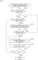
- Fig. 3 is a flowchart of the immediate movement default mode control process. It is a process executed by the control device 140 according to the operation of the controller.
- the control device 140 waits until the movement instruction is given (step S10).
- a movement instruction is given, by pressing the direction button 134 representing the direction of movement or the like (step S10), the control device 140 determines whether the pre-movement notice mode is set (step S11).
- the mode switching button 135 of the controller 130 is pressed, it is determined that the pre-movement notice mode is set, otherwise it is determined that the immediate movement mode is set. That is, if the operation is performed as usual without pressing the mode switching button 135, it operates in the immediate movement mode, and when the operator desires to display a pre-movement notice, the operator instruct the movement while pressing the mode switching button 135.
- the control device 140 displays a pre-movement notice of the direction of movement (step S12).
- the pre-movement notice is performed by displaying an arrow on the display unit 123 as shown in Fig. 2 and making a reaction in the display unit 150 corresponding to the direction of movement.
- This predetermined time can be arbitrarily set as a time for the operator to confirm the pre-movement notice, and can be about 2 to 3 seconds. This predetermined time may be adjustable.
- the control device 140 displays the direction of movement on the display units 123 and 150 (step S14) and moves the crane (step S15). The movement of the crane is repeated until a stop is indicated by the controller 130 (step S16), that is, until the button in the direction of movement is released or an emergency stop is indicated.
- the display when moving the crane (step S14) and the pre-movement notice (step S12) may be the same, or the display mode such as color, display size, and flashing may be changed. If the display mode is changed, there is an advantage that it calls attention to the fact that it is moving.
- step S11 When it is determined not in the pre-movement notice mode (step S11), that is, when it is determined in the immediate movement mode, the display and the movement in steps S14 to S16 are performed, skipping steps S12 and S13.
- responsiveness and workability can be ensured by performing normal operation in the immediate movement mode, and safety can be ensured by switching to the pre-movement notice mode as necessary when transporting a heavy object or the like.
- Fig. 4 is a flowchart of the immediate movement default mode control process as a modification.
- the control device 140 waits until a movement instruction is given (step S20). And when a movement instruction is given (step S20), the control device 140 determines whether it is in a pre-movement notice mode (step S21). These processes are the same as those described in Fig.3 .
- step S21 When it is determined in the pre-movement notice mode is (step S21), the control device 140 displays a notice of the direction of movement (step S22). Then, it is determined that a predetermined time has elapsed (step S23). If the predetermined time has not elapsed, the process returns to the judgment in step S21.
- the operation mode is immediately switched to the immediate movement mode by releasing the mode switching button 135 even before the predetermined time has elapsed.
- control device 140 displays the direction of movement and moves the crane until a stop is instructed (steps S24 to S26). The same applies when the immediate movement mode is from the beginning (step S21).
- a limit may be set on the cancellation of the pre-movement notice mode. For example, in step S22 of Fig. 4 , a waiting time shorter than the predetermined time of step S23 may be set, and only after the waiting time has elapsed, the process may proceed to step S23. In this way, a pre-movement notice is displayed during at least the waiting time, so a minimum level of safety can be ensured.
- pre-movement notice default mode control process An example of control in which the pre-movement notice mode is default and is switched to the immediate movement mode when the mode switching button 135 of the controller 130 is pressed (hereinafter referred to as "pre-movement notice default mode control process") will be described.
- FIG. 5 is a flowchart of the pre-movement notice default mode control process.
- the control device 140 waits until a movement instruction is given (step S30).
- a movement instruction is given (step S30)
- the control device 140 determines whether the pre-movement notice mode has been canceled (step S31). In this process, if the mode switching button 135 of the controller 130 is pressed, it is determined that the pre-movement notice mode is canceled, and if not, it is determined that it is a pre-movement notice mode. That is, if the operation is performed as usual without pressing the mode switching button 135, it operates in the pre-movement notice mode, and when the operator wants to cancel the pre-movement notice, the operator presses the mode switching button 135 and instructs a movement.
- the control device 140 displays a pre-movement notice of the direction of movement (step S32). Then, determine whether a predetermined time has elapsed (step S33). If the predetermined time has not elapsed, the process returns to the judgment in step S31. Therefore, the pre-movement notice mode can be canceled at any time by pressing the mode switching button 135 before a predetermined time has elapsed.
- step S13 of Fig. 3 may be applied, and the pre-movement notice mode may not be canceled.
- control device 140 displays the direction of movement and moves the crane until a stop is instructed (steps S34 to S36). These processes are the same as those described in Fig.3 .
- the pre-movement notice mode since the normal operation is performed in the pre-movement notice mode, the safety of the crane can be ensured. On the other hand, since the pre-movement notice mode can be canceled as necessary and switch to the immediate movement mode, it is possible to ensure responsiveness and workability.
- Figs. 3 and 4 show an example in which the immediate movement mode is the default
- Fig. 5 shows an example in which the pre-movement notice mode is the default.
- one of the control processes may be selected and applied, but furthermore, as shown in the following modifications, it may be possible to shift which one is the default.
- Fig. 6 is a flowchart of the movement control process.
- the upper left of the figure shows the controller 130A of the modification.
- the controller 130A is provided with a shift switch 136.
- the shift switch 136 may be rotated like an arrow r, and can switch between the immediate movement default mode and the pre-movement notice default mode by rotating left to right.
- the control device 140 waits until a movement instruction is given (step S40).
- a movement instruction is given (step S40)
- the control device 140 determines which one of the immediate movement mode or the pre-movement notice mode is to be set as default operation mode according to the state of the shift switch 136 (step S41).
- step S42 the immediate movement default mode control process is executed (step S42).
- the control process are as described in Figs. 3 and 4 .
- the pre-movement notice default mode control process is executed (step S43).
- the control process is as described in Fig.5 .
- the configuration of the crane system of the second embodiment is the same as that of the first embodiment described in Figs.1 and 2 .
- an example that can be switched between two operation modes, a pre-movement notice mode and an immediate movement mode was described.
- an example switching among a plurality of operation modes not limited to these two is shown.
- FIG. 7 is an explanatory diagram showing the flow of each operation mode.
- three operation modes of immediate movement mode, first pre-movement notice mode, and second pre-movement notice mode are used. Some operation modes may be omitted, or more operation modes may be used.
- a pre-movement notice is displayed when the movement direction is indicated. Then, after a predetermined time has elapsed, the crane moves automatically.
- the predetermined time can be arbitrarily determined, and can be divided into the first short pre-movement notice mode in which the crane moves after the first predetermined time has elapsed, and the first long pre-movement notice mode in which the crane moves after the second predetermined time longer than the first predetermined time has elapsed.
- the direction button 134 may be pressed in two stages, and when pressed lightly it becomes a direction indication, and when pressed deeper, it becomes an operation instruction.
- the direction button 134 is pressed while the operation instruction button 137 is pressed, it becomes a direction instruction, and when the operation instruction button 137 that has been pressed is released, it may become an operation instruction. Pressing the direction button 134 without pressing the operation instruction button 137 may result in a direction indication, and thereafter, pressing the operation instruction button 137 may result in an operation instruction.
- the operation instruction can take various other aspects. Note that any one of the above-described operation instruction methods shown in the figure may be employed, or may be selected from a plurality of operation instruction methods.
- FIG. 8 is an explanatory diagram showing the switching pattern of the operation mode. There are a total of six possible switching patterns.
- Pattern 1 is a switching between the immediate movement mode and the first short pre-movement notice mode. As described in the first embodiment, switching between the two can satisfy safety and responsiveness requirements depending on the situation.
- Pattern 2 is a switching between a first short pre-movement notice mode in which the time from the pre-movement notice to the start of movement is short, and a long first long pre-movement notice mode.
- a first short pre-movement notice mode in which the time from the pre-movement notice to the start of movement is short
- a long first long pre-movement notice mode For example, in the case of transporting a heavy load, it is preferable to start moving after carefully confirming safety after a pre-movement notice is displayed, so it is preferable to have a long time until the start of movement.
- the shorter the time until the start of movement the higher the workability.
- pattern 2 it is possible to change the time until the start of movement depending on the scene.
- the two operation modes can be switched according to various conditions, such as switching according to the type of suspending load and switching according to the skill level of the operator.
- Pattern 3 is a switching between the first long pre-movement notice mode and the second pre-movement notice mode.
- the first-length pre-movement notice mode has the advantage that movement can be avoided without giving an operation instruction, so that the complexity of operation can be avoided.
- the second pre-movement notice mode has the advantage that the movement can be started at any timing by the operation instruction. According to pattern 3, these advantages can be used differently depending on the situation. For example, the first long pre-movement notice mode is usually used, and the second pre-movement notice mode may be used when moving with empty cargo or when operating by a skilled operator.
- Pattern 4 is a switch between the second pre-movement notice mode and the immediate movement mode. As in the first embodiment, switching between the two can satisfy safety and responsiveness requirements depending on the situation.
- Pattern 5 is a switching between the first short pre-movement notice mode and the second pre-movement notice mode. Switching between the two has the same advantages as Pattern 3.
- Pattern 6 is a switch between the immediate movement mode and the first long pre-movement notice mode. As in the first embodiment, switching between the two can satisfy safety and responsiveness requirements depending on the situation.
- immediate movement mode control process A control process when the crane is operated in the immediate movement mode (hereinafter referred to as "immediate movement mode control process") will be described.
- Fig. 9 is a flowchart of the immediate movement mode control process.
- the control device 140 waits until the movement instruction is given (step S50).
- a movement instruction is given (step S50)
- the control device 140 displays the direction of movement on the display units 123 and 150 (step S51) and moves the crane (step S52). This display is not a pre-movement notice before the move, but is performed during the movement, and can be omitted.
- the movement of the crane is repeated until the controller 130 instructs it to stop (step S53).
- first pre-movement notice mode control process A control process when the crane is in operation in the first pre-movement notice mode (hereinafter referred to as "first pre-movement notice mode control process") will be described.
- FIG. 10 is a flowchart of the first pre-movement notice mode control process.
- the control device 140 waits until a movement instruction is given (step S60). When a movement instruction is given (step S60), the control device 140 displays a movement direction in advance (step S61). Then, determine whether a predetermined time has elapsed (step S62). If the predetermined time has not elapsed, the pre-movement notice is continued by returning to step S61.
- control device 140 displays the movement direction and moves the crane until a stop is instructed (steps S63 to S65).
- the predetermined time in step S62 is a preset time. Only one may be set, or multiple settings may be possible. When a plurality of settings is made, the operation mode set for a short predetermined time becomes the first short pre-movement notice mode, and the operation mode set for a long predetermined time becomes the first long pre-movement notice mode.
- second pre-movement notice mode control process A control process when the crane is in operation in the second pre-movement notice mode (hereinafter referred to as "second pre-movement notice mode control process") will be described.
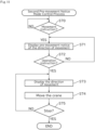
- FIG. 11 is a flowchart of the second pre-movement notice mode control process.
- the control device 140 waits until a movement instruction is given (step S70). When a movement instruction is given (step S70), the control device 140 displays a movement direction in advance (step S71). Then, it is determined whether there is an operation instruction (step S72). When there is no operation instruction, the procedure returns to step S71 and the pre-movement notice continues.
- control device 140 displays the movement direction and moves the crane until a stop is instructed (steps S73 to S75).
- Fig. 12 is a flowchart of the operation control process.
- This process is for controlling the operation of the crane by allowing switching of a plurality of operation modes.
- the control device 140 determines the operation mode to be executed from a plurality of operation modes (step S80). If it is not specified by the operator, the operating mode set as default will be executed. If the operator selects one of the operation modes or instruct switching the operation mode to a certain operation mode, the specified operation mode is executed.
- Switching of the operation mode can be performed by operating the mode switching button 135. For example, each time the mode switching button 135 is pressed, the immediate movement mode, the first pre-movement notice mode, and the second pre-movement notice mode may be switched sequentially. Instead, as a mode switching button, three push buttons corresponding to the immediate movement mode, the first pre-movement notice mode, and the second pre-movement notice mode may be provided, and one of them may be pressed to directly switch to the corresponding operation mode. It may be switchable by the shift switch 136 shown in Fig. 6 .
- the control device 140 then executes a control process according to the determined mode (step S81).
- the control process in each operation mode is as described in Figs. 9 to 11 .
- the determination of the operation mode may be performed only at the time when the process is started, or may be performed during control in each operation mode. In this case, during the control process in each operation mode, the presence or absence of an operation mode switching instruction is always detected, and when there is an operation mode switching instruction in the middle, it may be returned to the determination in step S80.
- the operation mode can be switched according to the instruction of the operator, and the operation of the crane can be controlled according to each operation mode.
- Switching of the operation mode may be performed according to the operation of the operator or may be performed automatically.
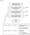
- FIG. 13 is a flowchart of the mode switching judgment process.
- the control device 140 automatically switches the operation mode.
- control device 140 inputs the operating state of the crane (step S90). Then, the control device 140 automatically determines whether to switch the operation mode according to the operating state of the crane (step 91), and instructs switching the operation mode determined in step 91 (step 92).
- the mode switching determination process of Fig. 13 may be performed only at the time when the process is started, or may be performed during control in each operation mode. In this case, during the control process in each operation mode, the mode switching determination process may be appropriately executed, and the operation mode switching determination may be performed in the middle.
- the operation mode can be switched according to the following two cases.
- Case 1 when a predetermined time has elapsed after the crane is stopped, the switch to the pre-movement notice mode is performed. Switching to another operation mode may be performed.
- the operation mode is preferably set to a pre-movement notice mode, which is highly safe, as an operation mode suitable for the start of the next new operation.
- the operating state in steps S90 and S91 means information necessary for performing these determinations. For example, whether the crane is moving, the elapsed time after stopping movement, and the like. At the same time, whether the crane has been winding up or down may be used.
- predetermined time in Case 1 and the predetermined time in Case 2 need not be the same, and a value suitable for each judgment may be arbitrarily set.
- the present invention is applicable to various types of cranes, not limited to overhead cranes. It can also be applied to moving objects other than cranes.
- these modes may be simply switched each time the mode switching button 135 is pressed, without setting any of the pre-movement notice mode, immediate movement mode, or the like as default.
- the present invention can be applied to remote-control of the movement of moving objects by wire or wireless.
Landscapes
- Engineering & Computer Science (AREA)
- Automation & Control Theory (AREA)
- Mechanical Engineering (AREA)
- Control And Safety Of Cranes (AREA)
Applications Claiming Priority (2)
| Application Number | Priority Date | Filing Date | Title |
|---|---|---|---|
| PCT/JP2022/013034 WO2023181096A1 (fr) | 2022-03-22 | 2022-03-22 | Système de fonctionnement à distance |
| PCT/JP2023/006339 WO2023181764A1 (fr) | 2022-03-22 | 2023-02-22 | Système de fonctionnement à distance |
Publications (2)
| Publication Number | Publication Date |
|---|---|
| EP4497719A1 true EP4497719A1 (fr) | 2025-01-29 |
| EP4497719A4 EP4497719A4 (fr) | 2026-04-08 |
Family
ID=88100191
Family Applications (1)
| Application Number | Title | Priority Date | Filing Date |
|---|---|---|---|
| EP23774363.8A Pending EP4497719A4 (fr) | 2022-03-22 | 2023-02-22 | Système de fonctionnement à distance |
Country Status (4)
| Country | Link |
|---|---|
| US (1) | US20250011141A1 (fr) |
| EP (1) | EP4497719A4 (fr) |
| JP (1) | JP7761313B2 (fr) |
| WO (2) | WO2023181096A1 (fr) |
Family Cites Families (6)
| Publication number | Priority date | Publication date | Assignee | Title |
|---|---|---|---|---|
| JP3458780B2 (ja) | 1999-07-30 | 2003-10-20 | コベルコ建機株式会社 | クレーンの表示装置 |
| JP2010254417A (ja) | 2009-04-23 | 2010-11-11 | Gogo:Kk | 方向表示装置、移動体操作システムおよび移動体の操作方法 |
| KR20120084473A (ko) * | 2011-01-20 | 2012-07-30 | (주)고려중기계 | 원터치 조작이 가능한 호이스트 크레인 |
| US10221047B2 (en) * | 2012-01-31 | 2019-03-05 | Gogoh Co., Ltd. | Display device of equipment and equipment provided with display device |
| JP3184806U (ja) * | 2013-05-07 | 2013-07-18 | 坤溢企業股▲ふん▼有限公司 | 天井クレーンの移動方向表示安全装置 |
| JP7732657B2 (ja) | 2020-09-04 | 2025-09-02 | 株式会社五合 | 制御システム、及び移動装置 |
-
2022
- 2022-03-22 WO PCT/JP2022/013034 patent/WO2023181096A1/fr not_active Ceased
-
2023
- 2023-02-22 WO PCT/JP2023/006339 patent/WO2023181764A1/fr not_active Ceased
- 2023-02-22 EP EP23774363.8A patent/EP4497719A4/fr active Pending
- 2023-02-22 JP JP2024509863A patent/JP7761313B2/ja active Active
-
2024
- 2024-09-19 US US18/890,494 patent/US20250011141A1/en active Pending
Also Published As
| Publication number | Publication date |
|---|---|
| WO2023181096A1 (fr) | 2023-09-28 |
| US20250011141A1 (en) | 2025-01-09 |
| EP4497719A4 (fr) | 2026-04-08 |
| WO2023181764A1 (fr) | 2023-09-28 |
| JPWO2023181764A1 (fr) | 2023-09-28 |
| JP7761313B2 (ja) | 2025-10-28 |
Similar Documents
| Publication | Publication Date | Title |
|---|---|---|
| US10495880B2 (en) | Controlling of lifting device | |
| US11802025B2 (en) | Remote control workstation | |
| US11339035B2 (en) | Controlling of lifting device | |
| JP2009227366A (ja) | 移動台車システム | |
| US20250011141A1 (en) | Remote control system | |
| JP2009301271A (ja) | 安全制御方法および安全制御システム | |
| JP2011051784A (ja) | 移動棚システム | |
| JP7300300B2 (ja) | クレーンの吊具の位置合わせ方法、及びクレーンシステム | |
| JP7732657B2 (ja) | 制御システム、及び移動装置 | |
| JP2010149989A (ja) | エレベータ | |
| CN112850496B (zh) | 遥控与自动跟踪相结合的塔式起重机智能安全控制方法 | |
| JP2002274611A (ja) | スタッカクレーンシステム | |
| KR200191025Y1 (ko) | 타워크레인의 화상감시장치 | |
| KR20230091337A (ko) | 다중 동작 변환모듈이 구비된 지게차 | |
| JP2002211715A (ja) | 荷搬送設備 | |
| JP2007320702A (ja) | エレベータの保守作業制御システム | |
| JP7840192B2 (ja) | クレーン制御システム | |
| JP7298313B2 (ja) | 通信方法、通信システム及び送信機 | |
| US20260048966A1 (en) | Crane system | |
| JPH0595979U (ja) | 移動式クレ−ンの遠隔操作装置 | |
| JPH03288704A (ja) | スタッカクレーンの制御装置 | |
| RU149775U1 (ru) | Система управления грузоподъёмной машиной (варианты) | |
| CN111061211A (zh) | 用于工程机械的监控系统及其控制方法 | |
| US20240208777A1 (en) | Crane operation support device and crane | |
| JP7172416B2 (ja) | 物流機器システム |
Legal Events
| Date | Code | Title | Description |
|---|---|---|---|
| STAA | Information on the status of an ep patent application or granted ep patent |
Free format text: STATUS: THE INTERNATIONAL PUBLICATION HAS BEEN MADE |
|
| PUAI | Public reference made under article 153(3) epc to a published international application that has entered the european phase |
Free format text: ORIGINAL CODE: 0009012 |
|
| STAA | Information on the status of an ep patent application or granted ep patent |
Free format text: STATUS: REQUEST FOR EXAMINATION WAS MADE |
|
| 17P | Request for examination filed |
Effective date: 20241015 |
|
| AK | Designated contracting states |
Kind code of ref document: A1 Designated state(s): AL AT BE BG CH CY CZ DE DK EE ES FI FR GB GR HR HU IE IS IT LI LT LU LV MC ME MK MT NL NO PL PT RO RS SE SI SK SM TR |
|
| DAV | Request for validation of the european patent (deleted) | ||
| DAX | Request for extension of the european patent (deleted) | ||
| A4 | Supplementary search report drawn up and despatched |
Effective date: 20260309 |
|
| RIC1 | Information provided on ipc code assigned before grant |
Ipc: B66C 13/46 20060101AFI20260303BHEP Ipc: B66C 13/40 20060101ALI20260303BHEP |