EP4497865A1 - Wäschetrocknungsgestell - Google Patents
Wäschetrocknungsgestell Download PDFInfo
- Publication number
- EP4497865A1 EP4497865A1 EP23774063.4A EP23774063A EP4497865A1 EP 4497865 A1 EP4497865 A1 EP 4497865A1 EP 23774063 A EP23774063 A EP 23774063A EP 4497865 A1 EP4497865 A1 EP 4497865A1
- Authority
- EP
- European Patent Office
- Prior art keywords
- clothes drying
- drying rack
- rack according
- chassis
- rods
- Prior art date
- Legal status (The legal status is an assumption and is not a legal conclusion. Google has not performed a legal analysis and makes no representation as to the accuracy of the status listed.)
- Pending
Links
Images




Classifications
-
- D—TEXTILES; PAPER
- D06—TREATMENT OF TEXTILES OR THE LIKE; LAUNDERING; FLEXIBLE MATERIALS NOT OTHERWISE PROVIDED FOR
- D06F—LAUNDERING, DRYING, IRONING, PRESSING OR FOLDING TEXTILE ARTICLES
- D06F57/00—Supporting means, other than simple clothes-lines, for linen or garments to be dried or aired
- D06F57/08—Folding stands
Definitions
- the present invention relates to a clothes drying rack, in which the rods where the clothes are hung are movable in relation to the chassis of the clothes drying rack, so that the separation between the rods can be changed at the user's discretion.
- clothes drying racks are well known for drying personal or household clothing for use in domestic environments. These clothes drying racks consist of rods or strings where the clothes to be dried are hung, which can be metallic, plastic, or made of other materials.
- a type of clothes drying rack is a folding type, which includes a chassis formed by bars that define frames and legs. In these frames, rods are extended longitudinally or transversely, usually metallic, on which the clothes to be dried are hung.
- foldable clothes drying racks have the advantage that when not in use, they take up very little space, being substantially flat, so they can be easily stored, which is especially practical for use in a household setting.
- clothes drying racks in general have the drawback that the rods where the clothes are hung are fixed, meaning they cannot be moved in relation to the chassis, so their spacing is also fixed and cannot be adjusted to the type of clothing being hung.
- the spacing between the rods can be reduced, while for larger household items, such as bed sheets, it is advisable that the spacing between the rods be greater.
- an objective of the clothes drying rack according to the present invention is to allow the rods where the clothes are hung to be easily placed in a desired position, regulating the separation between them as desired.
- the clothes drying rack according to the present invention is defined in claim 1, and comprises a chassis and a plurality of rods, the rods being movable with respect to the chassis.
- the rods can be placed in any suitable position relative to the chassis, according to the user's needs, allowing for the adjustment of the spacing between the rods.
- the clothes drying rack according to the present invention comprises a retention element.
- the retaining element is a ring located at the ends of the rods, which facilitates the movement of the rods relative to the chassis, and retains the rods by fitting into a plurality of housings of the chassis. These housings allow the rods to be held in a predetermined position, preventing the accidental displacement of the rods.
- these housings are evenly spaced along the chassis.
- said chassis defines frames and legs.
- the chassis defines a central frame, for example, rectangular or square, and two side frames, for example, U-shaped, with the side frames hinged to the central frame.
- These rods are preferably metallic, although they could be made of any suitable material.
- each retaining element comprises a movable arm that is movable between a release position and a retaining position.
- the movable arm advantageously comprises a protrusion.
- the retaining element is a threaded shaft movable between a release position and a retaining position
- the threaded shaft comprises a handle for rotating said threaded shaft from its release position to its retaining position, or vice versa.
- each rod comprises a ring at its ends, and the movable arm is connected through a pivot point to said ring.
- the protrusion is arranged at the end of the movable arm farthest from the pivot point, and said ring comprises a hole for housing said protrusion.
- chassis comprises complementary cavities with the hole of each ring.
- the retaining element can also include a fixed arm.
- the retaining element can be an engraving of the chassis.
- the retaining element is a plurality of curved tilting plates, which are movable between a retaining position, where it is placed on the chassis, and a release position, where it is separated from the chassis. To tilt all the curved plates together, they are joined together by a connecting bar.
- the retaining element is a protrusion that is inserted into a cavity of the chassis in its retaining position
- the protrusion is arranged on a ring disposed at the ends of the rods.
- the figures show a foldable clothes drying rack, but this is shown only by way of non-limiting example, as the clothes drying rack according to the present invention can also be a non-foldable clothes drying rack.
- the clothes drying rack according to the present invention comprises a chassis (1) and rods (2) that are movable with respect to said chassis (1).
- the chassis (1) is formed by bars that define a central frame (11) and two side frames (12), with the side frames (12) being hinged to the central frame (11).
- the chassis (1) also defines legs (13), which are also foldable, according to the depicted embodiment.
- the rods (2) extend transversely or longitudinally in said frames (11, 12), and include rings (3) at their ends, which surround the bars forming the frames (11, 12).
- the rods (2) can slide easily and guided along the bars that make up the frames (11, 12), allowing the rods (2) to be placed in any desired position.
- the chassis (1) in particular, in the frames (11, 12), comprises retaining elements, in this embodiment housings (4), to house the rings (3) of the ends of the rods (2).
- housings (4) are preferably distributed equidistantly in said frames (11, 12).
- the user can place at least some rods (2) in correspondence with the housings (4), with the upper interior part of the rings (3) housed in said housings (4).
- housings (4) in addition to determining rod (2) positions, allow retaining the rods (2) in place, preventing accidental displacement of said rods (2).
- the operation of the drying rack according to the present invention is very simple, as the user can simply move the rods (2) so that the spacing between them adapts to their needs. Specifically, you can place them with a minimal separation between them when you do not want to use them, as shown on the left side of figure 2 , they can be placed in correspondence with the housings (4), or in any intermediate position.
- the rods (2) extend transversely or longitudinally in said frames (11, 12), and include rings (30) at their ends, which surround the bars that make up the frames (11, 12).
- the rods (2) can slide easily and guided along the bars that make up the frames (11, 12), allowing the rods (2) to be placed in any desired position.
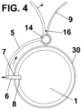
- Each of these rings (30) comprises a retaining element which, according to a second embodiment, includes a movable arm (5) provided with a protrusion (6). This movable arm (5) can be placed in a release position and a retaining position.
- the rods (2) can move freely along the frames (11, 12), while in the retaining position the rods (2) remain held in the desired position, unable to move along the rods (2).
- This retention is achieved by inserting the protrusion (6) into a hole (7) in the ring (30) and into a cavity (8) in the corresponding frame (11, 12).
- the movement from the release position to the retaining position, or vice versa, is achieved because the movable arm (5) is preferably articulated with respect to the ring (30) through a pivot point (14) attached to the ring (30), and the protrusion (6) is also preferably located at the end of the movable arm (5) farthest from the pivot point (14).
- this retaining element may also include a fixed arm (9) to facilitate the manipulation of the movable arm (5), with a spring (16) arranged between the movable arm (5) and the fixed arm (9).
- chassis (1) in particular, in the frames (11, 12), may include housings, not shown in figures 3 to 5 , but identical to those for the embodiments of figures 1 and 2 , to house the ends of the rods (2). These housings may be preferably distributed equidistantly in said frames (11, 12).
- the chassis (1) may include an additional engraving (15) with a ring engraving (30), for retaining the rods.
- This engraving (15) also serves as the retaining element.
- the operation of the drying rack according to the present invention is very simple, as the user can simply move the rods (2) so that the spacing between them adapts to their needs. Specifically, you can place them with a minimum spacing between them when they are not being used, they can be placed corresponding to the housings, if present, corresponding to the cavities (8) of the frames (11, 12), or in any intermediate position.
- the position of the hole (7) coincides with the cavity (8), and the user moves the movable arm (5) from the release position to the retaining position, inserting the protrusion (6) of the movable arm (5) into the inside of the cavity (8) and the hole (7), retaining the end of the rod (2) in this position.
- the moving arm (5) In order to allow the rod (2) to move, the moving arm (5) must be placed in the release position, performing the opposite movement.
- FIG. 5 A third embodiment of the retaining element is shown in figure 5 , wherein the retaining element is a threaded shaft (17) that is movable between a release position and a retaining position, and said threaded shaft (17) comprises a knob (18) for rotating said threaded shaft (17) from its release position to its retaining position, or vice versa.
- the retaining element is a threaded shaft (17) that is movable between a release position and a retaining position
- said threaded shaft (17) comprises a knob (18) for rotating said threaded shaft (17) from its release position to its retaining position, or vice versa.
- a fourth embodiment of the retaining element in which the retaining element consists of a plurality of tilting curved plates (19) that can be moved between a retaining position, where it is placed on the chassis (1), and a release position, where it is separated from the chassis (1). To tilt all the curved plates together, they are joined together by a connecting bar (20).
- a fifth embodiment of the retaining element in which the retaining element is a protrusion that is inserted into a cavity of the chassis in its retaining position, the protrusion (21) being located on a ring (30) arranged at the ends of the rods (2).
Landscapes
- Engineering & Computer Science (AREA)
- Textile Engineering (AREA)
- Holders For Apparel And Elements Relating To Apparel (AREA)
- Drying Of Solid Materials (AREA)
Applications Claiming Priority (3)
| Application Number | Priority Date | Filing Date | Title |
|---|---|---|---|
| ES202230458U ES1289330Y (es) | 2022-03-21 | 2022-03-21 | Tendedero |
| ES202231065U ES1293694Y (es) | 2022-06-23 | 2022-06-23 | Tendedero |
| PCT/ES2023/070171 WO2023180606A1 (es) | 2022-03-21 | 2023-03-17 | Tendedero |
Publications (2)
| Publication Number | Publication Date |
|---|---|
| EP4497865A1 true EP4497865A1 (de) | 2025-01-29 |
| EP4497865A4 EP4497865A4 (de) | 2026-04-01 |
Family
ID=88100114
Family Applications (1)
| Application Number | Title | Priority Date | Filing Date |
|---|---|---|---|
| EP23774063.4A Pending EP4497865A4 (de) | 2022-03-21 | 2023-03-17 | Wäschetrocknungsgestell |
Country Status (2)
| Country | Link |
|---|---|
| EP (1) | EP4497865A4 (de) |
| WO (1) | WO2023180606A1 (de) |
Family Cites Families (9)
| Publication number | Priority date | Publication date | Assignee | Title |
|---|---|---|---|---|
| SG92786A1 (en) * | 2001-03-16 | 2002-11-19 | Yong Tai Loong Pte Ltd | A laundry rack |
| ITPD20080001U1 (it) * | 2008-01-08 | 2009-07-09 | Gimi S P A | "stendibiancheria perfezionato" |
| JP2012017068A (ja) * | 2010-07-09 | 2012-01-26 | Aisin Seiki Co Ltd | 結合構造体 |
| KR101280139B1 (ko) * | 2011-11-30 | 2013-06-28 | 상 호 최 | 걸이봉 사이의 간격조절이 가능한 세탁물건조대 |
| KR20140095372A (ko) * | 2013-01-24 | 2014-08-01 | (주)에이치에스엘 | 빨래 건조대 |
| ITPD20130076A1 (it) * | 2013-03-26 | 2014-09-27 | Carpenteria Orazio Srl | Stenditoio telescopico per i panni |
| KR20160008932A (ko) * | 2014-07-15 | 2016-01-25 | 이시진 | 이동식 2단 접이형 레일 빨래 건조대 |
| KR101704976B1 (ko) * | 2016-06-24 | 2017-02-08 | 진향순 | 접이식 빨래건조대 |
| KR102413608B1 (ko) * | 2020-02-04 | 2022-06-28 | 이안제 | 조립식 빨래 건조대용 파이프 이음구조 |
-
2023
- 2023-03-17 EP EP23774063.4A patent/EP4497865A4/de active Pending
- 2023-03-17 WO PCT/ES2023/070171 patent/WO2023180606A1/es not_active Ceased
Also Published As
| Publication number | Publication date |
|---|---|
| WO2023180606A1 (es) | 2023-09-28 |
| EP4497865A4 (de) | 2026-04-01 |
Similar Documents
| Publication | Publication Date | Title |
|---|---|---|
| US4061395A (en) | Portable drawer assembly | |
| US6488160B2 (en) | Folding collapsible clothes rack | |
| US3874572A (en) | Collapsible hanger | |
| US2845317A (en) | Bracket for collapsible stand | |
| US1209679A (en) | Interlocking frame for stands and the like. | |
| EP4497865A1 (de) | Wäschetrocknungsgestell | |
| US672143A (en) | Telescopic traveling-bag. | |
| US1576629A (en) | Combined hall tree and drapery rack | |
| US2750242A (en) | Adjustable extension table apron | |
| KR20160131219A (ko) | 걸침날개부의 좌우 폭조절과 각도조절이 가능하여 보관 및 사용이 용이한 옷 거치대 | |
| US20070075204A1 (en) | Portable holder for hand-held appliances | |
| CN107287856B (zh) | 联排衣架 | |
| KR20190002111U (ko) | 옷걸이 | |
| KR20180136173A (ko) | 접이식 옷걸이 | |
| US4049948A (en) | Oven having an electric heating element with a hinged support | |
| KR101305050B1 (ko) | 분리식 세탁물 건조대 | |
| US993519A (en) | Curtain-stretcher. | |
| US2954150A (en) | Expandable garment hanger | |
| US343307A (en) | Extension-table | |
| US49779A (en) | John o | |
| US1095814A (en) | Umbrella-stand. | |
| US783853A (en) | Rack. | |
| US20150176898A1 (en) | Framed drying rack | |
| ES1293694U (es) | Tendedero | |
| CN101107394B (zh) | 具有合成树脂制部件的家用熨衣板 |
Legal Events
| Date | Code | Title | Description |
|---|---|---|---|
| STAA | Information on the status of an ep patent application or granted ep patent |
Free format text: STATUS: THE INTERNATIONAL PUBLICATION HAS BEEN MADE |
|
| PUAI | Public reference made under article 153(3) epc to a published international application that has entered the european phase |
Free format text: ORIGINAL CODE: 0009012 |
|
| STAA | Information on the status of an ep patent application or granted ep patent |
Free format text: STATUS: REQUEST FOR EXAMINATION WAS MADE |
|
| 17P | Request for examination filed |
Effective date: 20241016 |
|
| AK | Designated contracting states |
Kind code of ref document: A1 Designated state(s): AL AT BE BG CH CY CZ DE DK EE ES FI FR GB GR HR HU IE IS IT LI LT LU LV MC ME MK MT NL NO PL PT RO RS SE SI SK SM TR |
|
| DAV | Request for validation of the european patent (deleted) | ||
| DAX | Request for extension of the european patent (deleted) | ||
| A4 | Supplementary search report drawn up and despatched |
Effective date: 20260302 |
|
| RIC1 | Information provided on ipc code assigned before grant |
Ipc: D06F 57/06 20060101AFI20260224BHEP Ipc: D06F 57/08 20060101ALI20260224BHEP |