EP4497888A1 - Structure de renforcement pour former un plancher ou une dalle de plafond en béton triangulaire - Google Patents
Structure de renforcement pour former un plancher ou une dalle de plafond en béton triangulaire Download PDFInfo
- Publication number
- EP4497888A1 EP4497888A1 EP24190658.5A EP24190658A EP4497888A1 EP 4497888 A1 EP4497888 A1 EP 4497888A1 EP 24190658 A EP24190658 A EP 24190658A EP 4497888 A1 EP4497888 A1 EP 4497888A1
- Authority
- EP
- European Patent Office
- Prior art keywords
- concrete
- reinforcement structure
- mould
- triangular
- circumferential beam
- Prior art date
- Legal status (The legal status is an assumption and is not a legal conclusion. Google has not performed a legal analysis and makes no representation as to the accuracy of the status listed.)
- Withdrawn
Links
Images





Classifications
-
- E—FIXED CONSTRUCTIONS
- E04—BUILDING
- E04C—STRUCTURAL ELEMENTS; BUILDING MATERIALS
- E04C5/00—Reinforcing elements, e.g. for concrete; Auxiliary elements therefor
- E04C5/01—Reinforcing elements of metal, e.g. with non-structural coatings
- E04C5/06—Reinforcing elements of metal, e.g. with non-structural coatings of high bending resistance, i.e. of essentially three-dimensional [3D] extent, e.g. lattice girders
- E04C5/0645—Shear reinforcements, e.g. shearheads for floor slabs
-
- E—FIXED CONSTRUCTIONS
- E04—BUILDING
- E04C—STRUCTURAL ELEMENTS; BUILDING MATERIALS
- E04C5/00—Reinforcing elements, e.g. for concrete; Auxiliary elements therefor
- E04C5/01—Reinforcing elements of metal, e.g. with non-structural coatings
- E04C5/06—Reinforcing elements of metal, e.g. with non-structural coatings of high bending resistance, i.e. of essentially three-dimensional [3D] extent, e.g. lattice girders
-
- E—FIXED CONSTRUCTIONS
- E04—BUILDING
- E04B—GENERAL BUILDING CONSTRUCTIONS; WALLS, e.g. PARTITIONS; ROOFS; FLOORS; CEILINGS; INSULATION OR OTHER PROTECTION OF BUILDINGS
- E04B5/00—Floors; Floor construction with regard to insulation; Connections specially adapted therefor
- E04B5/16—Load-carrying floor structures wholly or partly cast or similarly formed in situ
- E04B5/17—Floor structures partly formed in situ
- E04B5/23—Floor structures partly formed in situ with stiffening ribs or other beam-like formations wholly or partly prefabricated
- E04B5/29—Floor structures partly formed in situ with stiffening ribs or other beam-like formations wholly or partly prefabricated the prefabricated parts of the beams consisting wholly of metal
-
- E—FIXED CONSTRUCTIONS
- E04—BUILDING
- E04B—GENERAL BUILDING CONSTRUCTIONS; WALLS, e.g. PARTITIONS; ROOFS; FLOORS; CEILINGS; INSULATION OR OTHER PROTECTION OF BUILDINGS
- E04B5/00—Floors; Floor construction with regard to insulation; Connections specially adapted therefor
- E04B5/43—Floor structures of extraordinary design; Features relating to the elastic stability; Floor structures specially designed for resting on columns only, e.g. mushroom floors
-
- E—FIXED CONSTRUCTIONS
- E04—BUILDING
- E04C—STRUCTURAL ELEMENTS; BUILDING MATERIALS
- E04C2/00—Building elements of relatively thin form for the construction of parts of buildings, e.g. sheet materials, slabs, or panels
- E04C2/02—Building elements of relatively thin form for the construction of parts of buildings, e.g. sheet materials, slabs, or panels characterised by specified materials
- E04C2/04—Building elements of relatively thin form for the construction of parts of buildings, e.g. sheet materials, slabs, or panels characterised by specified materials of concrete or other stone-like material; of asbestos cement; of cement and other mineral fibres
- E04C2/06—Building elements of relatively thin form for the construction of parts of buildings, e.g. sheet materials, slabs, or panels characterised by specified materials of concrete or other stone-like material; of asbestos cement; of cement and other mineral fibres reinforced
-
- E—FIXED CONSTRUCTIONS
- E04—BUILDING
- E04C—STRUCTURAL ELEMENTS; BUILDING MATERIALS
- E04C3/00—Structural elongated elements designed for load-supporting
- E04C3/02—Joists; Girders, trusses, or trusslike structures, e.g. prefabricated; Lintels; Transoms; Braces
- E04C3/29—Joists; Girders, trusses, or trusslike structures, e.g. prefabricated; Lintels; Transoms; Braces built-up from parts of different material, i.e. composite structures
- E04C3/293—Joists; Girders, trusses, or trusslike structures, e.g. prefabricated; Lintels; Transoms; Braces built-up from parts of different material, i.e. composite structures the materials being steel and concrete
Definitions
- the present disclosure in some embodiments thereof, relates to a reinforcement structure and, more specifically to a reinforcement structure for forming a triangle shape concrete floor or ceiling slab, but not exclusively, to a particular triangle shape.
- Reinforced prefabrication concrete floor structures are a type of construction technology that may involve the manufacture of concrete flooring or ceiling elements offsite in a controlled factory environment, before being transported to a building site for installation.
- reinforced prefabrication concrete floor structures may be the use of pre-stressed concrete that allows for greater structural efficiency and increased load-bearing capacity.
- Other advancements may include the use of lightweight aggregate concrete and the incorporation of various types of reinforcement such as steel fibers, in order to enhance the structural integrity and durability of the flooring or ceiling elements.
- Further advancements may include the use of advanced manufacturing techniques such as three dimensional (3D) printing and robotic fabrication, in order to improve the precision and consistency of prefabricated flooring or ceiling elements.
- 3D three dimensional
- Pre-stressed and post-stressed concrete are both techniques used to reinforce concrete elements and improve their load-bearing capacity. Both techniques involve the use of high-strength steel cables or bars that are embedded in the concrete.
- pre-stressed concrete the cables or bars included in a reinforcement structure are stressed before or after the concrete is poured and allowed to cure. The cables or bars are anchored to the ends of the concrete element, and when the concrete is poured, the concrete element is forced into compression around the cables or bars by being tensed or held taut. This compression increases the strength of the concrete, making it more resistant to bending and cracking.
- Pre-stressed concrete may be used in the construction of bridges, parking structures, and buildings with long spans.
- the cables or bars are tensed or held taut after the concrete has been poured and allowed to partially cure. Once the concrete has reached the appropriate strength, the cables or bars included in a reinforcement structure are anchored to the ends of the concrete element and then tensed or held taut, to apply thereby, a compressive force to the partially cured concrete to form a compressed concrete slab.
- the technique of post-stressed concrete may be used in the construction of floors, roofs, and other horizontal surfaces.
- a reinforcement structure for forming a concrete slab comprising a triangular circumferential beam.
- Multiple central ribs where each of the central ribs are attached between two sides of the three sides of the triangular circumferential beam.
- Multiple reinforcing bars included in the triangular circumferential beam where each of the reinforcing bars are tensionally attached between two corners of the triangular circumferential beam.
- Multiple conduits may house the multiple reinforcing bars and a mould that houses a reinforcement cage.
- the reinforcement cage may surround at least the triangular circumferential beam and multiple reinforcing bars.
- One or more reinforcement meshes placed on top of the reinforcement cage and on the bottom of the mould. After pouring concrete into the mould and allowing a setting of the concrete, a tensile force may be applied to multiple reinforcing bars between two corners of the triangular circumferential beam responsive to the setting, forms the concrete slab as a compressed concrete slab.
- a casting pattern of the mould may enable the routing, and attachment of multiple conduits in the concrete slab and the connection between at least one of another adjacent concrete slab or another building element.
- the mould may be constructed from steel, carbon fibre, aluminum, and fiberglass.
- the mould may be further attached to a moveable platform to enable a level casting of concrete into the mould.
- the moveable platform may be located in a factory, at a construction site or a mobile factory. The utilization of the mobile factory may enable the fabrication of the reinforcement structure.
- the multiple conduits may house and route electrical cables, water lines, and gas lines to various locations on or in the reinforcement structure.
- the multiple conduits may be connectable to other respective conduits included in a vertical column that attaches to the reinforcement structure. The tensile force may be applied prior to the concrete setting, thereby forming the concrete slab as a pre-stressed concrete slab.
- the reinforcement structure may further include multiple fasteners disposed about each of the sides of the triangular circumferential beam to enable mechanical attachment of one side of the triangular circumferential beam to another corresponding side of another adjacent triangular circumferential beam.
- One or more cantilever beams may be attached perpendicular to one or more plate sections, the vertical column, and a side between each corner of the triangular circumferential beam to enable a balcony or a canopy on the exterior of a building structure.
- An eye attached to one or more plate sections may be included to enable the lifting by a hook and placing of the reinforcement structure adjacent to another structural member or another adjacent triangular circumferential beam.
- the eye may be attachable to the one or more plate sections prior to pouring and setting of concrete or post pouring and setting of concrete.
- the triangular circumferential beam may be a right triangle, an isosceles right triangle, 30 degrees (°)-60°-90° triangle, oblique triangle, or irregular triangular shape.
- a method of manufacturing a reinforcement structure for forming a concrete slab by constructing a triangular circumferential beam. Multiple central ribs are attached between two sides of the three sides of the triangular circumferential beam. Multiple reinforcing bars are tensionally attached between two corners of the triangular circumferential beam.
- a bottom reinforcement mesh may be attached into a mould.
- the reinforcement structure may be placed into the mould, the mould may include a reinforcement cage that surrounds and attaches to at least the triangular circumferential beam and the multiple reinforcing bars.
- a top reinforcement mesh may be attached on top of the reinforcement cage.
- Concrete may be poured into the mould and allowing the setting of the concrete.
- a tensile force may be applied to the multiple reinforcing bars between two corners of the triangular circumferential beam responsive to the setting of the concrete to form the concrete slab as a compressed concrete slab, where the applying of the tensile force is enabled by the housing. The tensile force may be applied prior to the concrete setting, thereby forming the concrete slab as a pre-stressed concrete slab.
- a casting pattern of the mould may enable the routing and attachment of the multiple conduits in the concrete slab and the connection between one or more adjacent concrete slabs or another building element.
- the mould may be constructed from steel, carbon fibre, aluminum, or fiberglass.
- the mould may further be attached to a moveable platform to enable a level casting of concrete into the mould located in a factory, at a construction site or a mobile factory.
- the utilization of the mobile factory may enable the fabrication of the reinforcement structure, the multiple conduits, and the one or more reinforcement meshes to be attached to the mould prior to pouring of concrete.
- the triangular shape of the concrete flooring or ceiling elements utilizing a reinforcement structure described herein allows for more flexibility in the design of concrete flooring or ceiling elements, allowing for the creation of unique and creative architectural forms.
- prefabrication offsite of the concrete flooring or ceiling elements allows for more accurate measurements and cuts, reducing the amount of material waste during construction of the concrete flooring or ceiling elements.
- the triangular shape of the flooring or ceiling elements can improve thermal insulation, reduce energy consumption and costs.
- a triangular shaped concrete floor element can improve thermal insulation by utilizing the principles of geometry and insulation materials.
- the shape of a triangular floor element can create a larger surface area per volume of material used compared to a traditional rectangular shape. The increased surface area allows for more space to incorporate insulation materials, which can significantly reduce heat transfer through a floor.
- the triangular shape can be designed with an inward slope towards the building interior. This inward slope can help to create a thermal break, reducing the amount of heat that may be transferred between the interior and exterior of the building.
- the insulation material used in the floor element can also play a crucial role in thermal insulation.
- EPS expanded polystyrene
- XPS extruded polystyrene
- the triangular shape of the flooring or ceiling elements allows for greater adaptability to different types of foundations and ground conditions, making it suitable for a wide range of building sites. Attaching the floor structure on-site allows for more customization and adaptability to the existing structure or site condition.
- the modular design of the triangular shaped concrete floor elements can also incorporate the necessary conduits for electricity, gas, and water lines to connect together and between floors. These conduits can be integrated into the pre-fabricated triangular elements, providing a seamless connection between floors and improving the efficiency of the building's infrastructure.
- Vertical pillars can be constructed between each triangular floor element, which also incorporate the conduits for the building's utilities. These pillars provide a stable and secure connection between the floors, ensuring that the conduits remain intact and functional.
- the triangular shape may provide more surface area per volume of material used, allowing for more space to accommodate the conduits. This can reduce the need for additional space or infrastructure, saving construction costs and improving the overall efficiency of the building.
- the modular design of the triangular shaped floor elements allows for easy modification or replacement of the conduits in the future. The modular design can be particularly useful for buildings that require changes to their infrastructure due to evolving needs or technological advancements.
- two prefabricated triangular flooring or ceiling elements that are reattachable together to form a rectangle may be smaller and lighter than rectangular concrete slabs providing the same floor area, as a prefabricated triangular flooring element can be lifted by a crane on site and transported more easily, reducing the need for heavier lifting requirements and transportation costs.
- the use of prefabrication allows for the concrete flooring or ceiling elements to be manufactured offsite in a controlled factory environment, reducing the time and labor required for installation on the building site. Since prefabrication reduces labor and site time, it can be cost-effective and also reduces the risk of errors on the site.
- the use of sustainable materials and techniques in the production of prefabricated concrete flooring can reduce the environmental impact of construction, making the structure more eco-friendly.
- the triangular shape of the flooring or ceiling elements allows for a more efficient distribution of load compared to other shapes such as squares or rectangles.
- the triangular shape distribute loads along their sides evenly and efficiently, reducing the overall weight and size of the structure while still maintaining its strength and stability.
- the forces are distributed along its three sides, creating a more stable and balanced structure.
- the more stable and balanced structure allows for a reduction in the amount of material required to support a given load, resulting in a lighter and more efficient structure.
- the angles of the triangle also help to resist bending and compressive forces, which may be common in flooring structures.
- a square or rectangular shape distributes the load mainly through two parallel sides, creating a structure that may be less stable and requires more material to support the same load. Additionally, the corners of squares and rectangles may be weak points that may be susceptible to bending and compressive forces, which can cause the structure to fail under heavy loads.
- a three-cornered moveable platform attached to a mould may allow for simpler leveling, even weight distribution, and more efficient pouring of concrete, making it a practical and time-saving choice by ensuring that the mould is properly supported, allowing concrete to be poured evenly and at the desired level, thereby, ensuring the structural integrity and safety of a concrete slab.
- Further utilization of hydraulic jacks movably attached to the moveable platform also enable the correct repositioning and relevelling of a reinforcement structure and the other construction elements attached to the reinforcement structure during the pouring of concrete into the mould.
- the correct repositioning and relevelling of the reinforcement structure may also be as a result of subsequent re-location of the moveable platform between projects on a particular floor level and lifts of the platform/ mould to other floor levels after the pouring of concrete into the mould.
- the present disclosure in some embodiments thereof, relates to a reinforcement structure and, more specifically to a reinforcement structure for forming a triangle shape concrete floor or ceiling slab, but not exclusively, to a particular triangle shape.
- triangular shape of post-stressed concrete slabs by utilization of a reinforcement structure to form a post-stressed concrete slab allows for greater adaptability to different types of foundations and ground conditions, making it suitable for a wide range of building sites. Attaching the floor or ceiling structure on-site allows for more customization and adaptability to the existing structure or site condition.
- the modular design of post-stressed concrete slab can also incorporate the necessary conduits for electricity, gas, and water lines to connect together and between floors. Conduits can be integrated into the pre-fabricated post-stressed concrete slab, to provide a seamless connection between floors and improving the efficiency of an infrastructure for a building.
- Columns can be constructed between each post-stressed concrete slab, which also incorporate the necessary conduits for the utilities of a building. Columns provide a stable and secure connection between the floors, ensuring that conduits remain intact and functional.
- the triangular shape of post-stressed concrete slabs may provide more surface area per volume of material used, allowing for more space to accommodate the conduits. More space to accommodate conduits can reduce the need for additional space or infrastructure, saving construction costs and improving the overall efficiency of the building.
- the modular design of the triangular shaped floor or ceiling elements may allow for easy modification or replacement of conduits in the future. The modular design can be particularly useful for buildings that require changes to their infrastructure due to evolving needs or technological advancements.
- each block in the flowchart or block diagrams may represent a module, segment, or portion of instructions, which comprises one or more executable instructions for implementing the specified logical function(s).
- the functions noted in the block may occur out of the order noted in the figures.
- two blocks shown in succession may, in fact, be executed substantially concurrently, or the blocks may sometimes be executed in the reverse order, depending upon the functionality involved.
- FIG. 1A shows a plan view of a reinforcement structure 1 for forming a concrete slab, in accordance with some embodiments.
- reinforcement structure 1 is triangular with three corners resting on three vertical support pillars or columns 5.
- the hypotenuse of triangular reinforcement structure 1 includes a circumferential beam B1.
- Triangular reinforcement structure 1 includes a circumferential beam B2 which is bent and/or formed at ninety degrees (90°) to form the other two sides of triangular reinforcement structure 1.
- Circumferential beam B1 at two ends attaches to circumferential beam B2 to form two respective corners C1 and C2 that include two respective anchor plates 22.
- Central ribs B3, in a cross format connects horizontally between the hypotenuse and one side of circumferential beam B2 opposite corner C2. Similarly, another central rib B3 located above the cross format connects between the hypotenuse and one side of circumferential beam B2 opposite corner C2. Central ribs B3, in the cross format connects vertically between the hypotenuse and the other side opposite of corner C1 of circumferential beam B2. Similarly, another central rib B3 located to the right of the cross format connects between the hypotenuse and one side of circumferential beam B2 opposite corner C1.
- Reinforcing bars 2 are attached between the two corners C1 and C2 along the hypotenuse of triangular reinforcement structure 1 formed by circumferential beam B1. Further, another set of reinforcing bars 2 attach at the two corners C1 and C2 to two respective anchor plates not shown but similar to anchor plates 22.
- the two anchor plates are also attached to the respective two ends of where circumferential beam B1 is attached to circumferential beam B2.
- a plate 19 is included and attached to circumferential beam B2 at the ninety degree corner. Plate 19 in turn attaches to column 5.
- the two anchor plates further attach to two respective plates (not shown) similar to plate 19. The two plates enable the two corners C1 and C2 of a formed concrete slab to attach to the two respective columns 5.
- the path of the other set of reinforcing bars 2 start at one corner C1, where one end of reinforcing bars 2 are attached to an anchor plate (not shown).
- the path of reinforcing bars 2 then proceeds through one side of circumferential beam B2 around the ninety degree (90°) angle of circumferential beam B2.
- the path of reinforcing bars 2 then proceeds along the other side of circumferential beam B2.
- the other end of reinforcing bars 2 attaches to another anchor plate (not shown) of the other corner C2.
- Circumferential beams B1 and B2 may be implemented as enclosed box sections in steel, aluminum or carbon fibre.
- Circumferential beams B1 and B2 may be implemented in an open U box section.
- reinforcing bars 2 may be housed in multiple conduits so that when concrete is poured and partially sets around the conduits, the reinforcing bars are tensionally moveable between two corners C1 and C2 of the triangular circumferential beam formed by circumferential beams B2 and B1, where reinforcing bars 2 attach to the anchor plates (not shown) and anchor plates 22 respectively.
- Triangular reinforcement structure 1 is shown as a right angled triangle but may also be an isosceles right triangle, 30 degrees (°)-60°-90° triangle or an oblique triangle.
- apertures 12 may be utilized to enable two triangular reinforcement structures 1 to be attached together. Attaching together includes two hypotenuses of circumferential beams B1 to be joined together or the two other sides of circumferential beams B2 to be joined together. Apertures 12 may also be utilized to enable conduits to pass through into an area of a formed concrete slab to receive electrical cables, water lines, and gas lines from other formed concrete slabs and other concrete structures that include similar conduits.
- Reinforcing bars 2 that are stressed following pouring and partial curing of the concrete are an example of the formation of a post-stressed concrete slab. Whereas, reinforcing bars 2 that are stressed prior to pouring and curing of the concrete are an example of the formation of a pre-stressed concrete slab.
- FIG. 1B shows a cross sectional view AA of reinforcement structure 1 shown in FIG. 1A as a formed concrete slab, in accordance with some embodiments.
- concrete 13 is shown (white portions) and circumferential beams B1, B2 and central ribs B3 attached between two sides of the three sides of the circumferential beams B1 and B2 of reinforcement structure 1.
- corner C2 are concrete 13 and plate 26 that includes reinforcing bars 2 and anchor plates 22 (both not shown).
- a similar arrangement is made at corner C 1.
- At the ninety degrees (90°) corner is included concrete 13 and plate 19 that in turn attaches to column 5 (not shown).
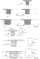
- FIG. 2A shows a further detailed plan view of corners C1 or C2 of reinforcement structure 1, in accordance with some embodiments.
- the plan view shows circumferential beam B2 attached to circumferential beam B1 and specific corners C and D of column 5.
- plates 26 attached therein include the means to attach to column 5.
- anchor plate 22 attaches to both plates 26 and circumferential beams B2 and B1, and similar arrangement is provided at corner C1.
- U bolts 25 attach to the horizontal portion of plates 26 that attach to circumferential beams B2 and B1 to form corners C1 and C2.
- Anchor plate 24 attaches to circumferential beam B2 at corner C2 and similar arrangement is provided at corner C1.
- pocket formers 23b and wedges at anchor plate 24, multiple reinforcement bars 2 are attached to anchor plate 24 by multiple respective pocket formers 23b and wedges.
- Pocket formers 23b and wedges at corners C1 and C2 enable a tensile force to be applied and fixed across circumferential beam B2.
- the tensile force being applied by connection of a hydraulic jack to reinforcement bars 2 and its operation applied to reinforcement bars 2 that go through pocket formers 23b.
- pocket formers 23a and wedges are provided at corners C1 and C2 enable a tensile force to be applied and fixed across circumferential beam B1.
- the tensile force being applied again by connection of a hydraulic jack to reinforcement bars 2 and its operation applied to reinforcement bars 2 that go through pocket formers 23a.
- the tensile force applied therefore, places the cross sectional area of reinforcement structure 1 filled with concrete 13 that has set to be held in compression around the perimeter of reinforcement structure 1 to form a post-stressed concrete slab.
- FIG. 2B shows further details of a side view of corners C1 or C2 of reinforcement structure 1, in accordance with some embodiments.
- the side view includes corner D of column 5 and circumferential beam B1 perpendicular to column 5.
- the horizontal portion of plate 26 that attaches to circumferential beams B1 to form corners C1 and C2 is shown attached to column 5.
- Prefabricated membrane 27 is shown on top of circumferential beam B1.
- FIG. 2C shows further details of a side view of corners C1 or C2 of reinforcement structure 1, in accordance with some embodiments.
- the side view includes corner C of column 5 and circumferential beam B2 perpendicular to column 5.
- the horizontal portion of plate 26 that attaches to circumferential beams B2 to form corners C1 and C2 is shown attached to column 5. Included and attached to in the horizontal portion of plate 26 are U bolts 25 that attach to the horizontal portion of plates 26 that attach to circumferential beams B2 and B1 to form corners C1 and C2.
- U bolts 25 are utilized to enable a crane to lift reinforcement structure 1 or a concrete formed slab using reinforcement structure 1 into position above columns 5.
- bolt holes in the horizontal portion of plates 26 enable fastening reinforcement structure 1 or a concrete formed slab to column 5.
- anchor plates 22, 24 and 26 enables attachment of a triangular circumferential concrete beam perpendicular to column 5, attachment to another triangular circumferential beam, attachment to a walls of a building, and attachment to the shell of a building.
- FIG. 2D and FIG. 2E show further details of end views view of two circumferential beams B1, B2 and a central rib B3 of reinforcement structure 1, in accordance with some embodiments.
- Drawing (a) and drawing (i) shows central rib B3 filled with concrete 13 and the metal elements 21 of central rib B3 respectively.
- Metal elements 21 in central rib B3 includes a U shaped metal wall enclosure 21a and a top potion 21b which in the fabrication of reinforcement structure 1 is placed and attached underneath membrane 27.
- Membrane 27 may include an upper metal plate 21d atop an upper mesh 3 and a layer of concrete 13.
- Membrane 27 may be pre-fabricated or formed in the fabrication of reinforcement structure 1.
- Reinforcement bars 21c may also be included in central rib B3.
- anchor plate 24 attaches to circumferential beam B2 at corner C2 (not shown) and a similar arrangement is provided at corner C1 (not shown).
- Multiple reinforcement bars 2 are attached to anchor plate 24 by multiple respective pocket formers 23b and wedges held in place by concrete 13. Pocket formers 23b and wedges at corners C1 and C2 enable a tensile force to be applied and fixed across circumferential beam B2. The tensile force being applied by connection of a hydraulic jack to reinforcement bars 2 and its operation applied to reinforcement bars 2 that go through pocket formers 23b.
- pocket formers 23a and wedges held in place by concrete 13 are provided at corners C1 and C2 enable a tensile force to be applied and fixed across circumferential beam B1.
- the tensile force being applied again by connection of a hydraulic jack to reinforcement bars 2 and its operation applied to reinforcement bars 2 that go through pocket formers 23a.
- Drawings (c) and (e) show set concrete 13 at the ends of circumferential beams B2 and B1 respectively that do not have pocket formers and wedges attached.
- FIG. 3A shows further details of further reinforcement elements attached to reinforcement structure 1 prior to pouring of concrete, in accordance with some embodiments.
- the reinforcement elements are three rebar cages or tied columns that surround the hypotenuse side formed by circumferential beam B1 and two rebar cages that surround the sides formed by circumferential beam B2.
- Each rebar cage is made up of longitudinal bars 42 that are normally distributed with equal spacing to form the outside of a rectangular column.
- Transverse reinforcing bars 43 are placed around and attached to longitudinal bars 42, with the longitudinal bars 42 and transverse reinforcing bars 43 being held together with ties, clamps, or, in special cases, with welds.
- a rebar cage may include guides for centering the rebar cage to encompass circumferential beams B1 and B2.
- the three rebar cages are attached to each other at the three corners of reinforcement structure 1 so that a triangular shaped concrete slab may be subsequently formed.
- Central ribs B3 may or may not also be surrounded with similar rebar cages if required.
- Multiple reinforcement bars 2 are shown by three dashed/ dotted line in the hypotenuse formed by circumferential beam B1 and in the two sides formed by circumferential beam B2
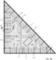
- FIG. 3B and 3C shows yet further reinforcement elements attached to reinforcement structure 1 and a cross section BB of circumferential beam B2 respectively, in accordance with some embodiments.
- FIG. 3B is the same as FIG. 3A in that it includes circumferential beams B1 and B2, transverse reinforcing bars 43, longitudinal bars 42, central ribs B3 and reinforcement bars 2.
- the further re-enforcement elements include two triangular reinforcement meshes 3 placed and attached (not shown) on top and bottom of the three rectangular rebar cages or tied columns that surround the hypotenuse side formed by circumferential beam B1 and the two rebar cages that surround the sides formed by circumferential beam B2.
- Cross sectional view BB is of one of the sides formed by circumferential beam B2.
- Cross sectional view BB shows two triangular reinforcement meshes 3 placed and attached on top and bottom of the rebar cage or tied column that surrounds circumferential beam B2.
- the rectangular rebar cage or tied column includes transverse reinforcing bars 43 around and attached (not shown) to longitudinal bars 42.
- Circumferential beams B2 is shown implemented as an open U box section. In the open U box section case, reinforcing bars 2 may be housed in multiple conduits 2a so that when concrete 13 is poured and partially sets around conduits 2a, reinforcing bars 2 are tensionally moveable between the two corners C1 and C2.
- Circumferential beams B2 implemented as a closed rectangular box section may eliminate the need for conduits 2a since reinforcing bars 2 are now no longer covered directly by concrete 13 when poured into mould 45 in the formation of triangular concrete slab.
- Mould 45 may be constructed from steel, wood, carbon fibre, aluminum, and fiberglass.
- conduits 44 may be used to house, protect and enable the run electric cables, gas and water lines to equipment housing 38 that may be attached or recessed into the underside for a formed triangular concrete slab prior to pouring of concrete.
- Equipment housing 38 for example may be for a sprinkler system, an air conditioning unit that requires electricity supply and gas suction and blow lines or may be lighting junction box.
- apertures 12 may also be utilized to enable conduits 44 to pass through into an area of another adjacent formed triangular concrete slab and other concrete structures that include similar conduits 44.
- a casting pattern of mould 45 may further enable the routing and attachment of conduits 44 in the triangular concrete slab and the connection of conduits 44 in another adjacent triangular concrete slab another building element such as a rebar cage.
- the re-bar cage for example may be utilized to form a concrete vertical column attachable perpendicular to a triangular concrete slab.
- the concrete vertical column may include guides for centering the rebar cage around conduits 44, enable the routing of conduits 44 by a casting pattern enabled in the in the vertical column by the use of Styrofoam guides/ spacers 47 for example.
- the casting pattern enabled in the vertical column further to enable the connection between the conduits 44 of the vertical column to connect to the conduits of a triangular concrete slab.
- FIG. 3D shows a perspective view of a moveable platform 32, in accordance with some embodiments.
- Moveable platform 32 includes a triangular frame which is adapted to hold mould 45 (not shown) and three legs L1, L2 and L3 moveably attached perpendicular to each corner of the triangular frame. The other ends of each the three legs L1, L2, and L3 are attached to casters or wheels W1, W2, and W3 respectively. Wheels W1, W2, and W3 enable horizontal positioning of the triangular frame back and forth, left and right in the XY plane that is parallel to a floor or other surface.
- Three legs L1, L2, and L3 further include a height adjustments H1, H2, and H3 of the triangular frame relative to a floor or other surface in the vertical Z direction.
- Height adjustments of H1, H2, and H3 of the triangular frame with the use of jacks may further enable the positioning and attachment of a pre-stressed or post-stressed triangular concrete slab to form a flooring or ceiling element.
- the location of pouring of concrete 13 into mould 45 may be in a factory, at a construction site or a mobile factory.
- the mobile factory may enable the fabrication of reinforcement structure 1, conduits 44, and the attachment of reinforcement mesh 3 to the bottom of mould 45 and the attachment of a second mesh 3 to the top of reinforcement structure 1 placed in mould 45 prior to pouring of concrete 13.
- hydraulic Jacks may be connected/anchored at the corners of the screeds of mould 45 and further at the bottom of the corners to raise the screeds and reinforcement structure 1 placed in mould 45 prior to pouring of concrete 13.
- reinforcement structure 1 is attached to a constructions element that includes longitudinal bars 42, transverse reinforcing bars 43, and triangular reinforcement meshes 3 placed and attached on top and in the bottom of mould 45.
- Utilization of the hydraulic jacks enable the correct repositioning and relevelling of reinforcement structure 1 and the construction element during the pouring of concrete 13 into mould 45.
- the correct repositioning and relevelling of reinforcement structure 1 may also be as a result of subsequent re-location of moveable platform 32 between projects on a particular floor level and lifts to other floor levels after the pouring of concrete.
- unevenness of a platform structure attached to a mould may be more likely to cause the mould to tilt or shift, which can result in concrete being poured unevenly.
- the concrete being poured unevenly can lead to structural problems in a finished product, reducing its integrity and potentially compromising its safety.
- an uneven platform can cause cracks and weaknesses in a building foundation or bridge support for example, leading to catastrophic failure.
- a level platform is essential to ensure that the concrete sets evenly and at the desired level. If the platform is not level, the concrete may settle or slump in one area, causing a depression or low spot in the finished product. Precise leveling may be particularly crucial when pouring large or complex structures.
- a three-cornered platform such as moveable platform 32, may be easier to level than a four-cornered platform due to weight distribution of moveable platform 32.
- moveable platform 32 each of the three corners has an equal share of the weight that may make it easier to find a balance point that will keep mould 45 attached to moveable platform 32 level.
- a four-cornered platform to form a rectangular concrete slab for example, has four points of weight distribution that may make it more challenging to find the exact balance point, especially if a floor or other surface of a building site or factory floor is uneven and/ or not level.
- a three-cornered platform such as moveable platform 32
- height adjustments H1, H2, and H3 can be made to just two of the three corners to level the triangular frame.
- the height adjustments H1, H2, and H3 of just two of the corners to level the triangular frame therefore, may make the leveling process quicker and more efficient, allowing for faster completion of a concrete pouring process and reducing the overall time required to form a concrete slab.
- adjusting the height of each corner of a four-cornered platform separately may be a time-consuming and labor-intensive task, especially when dealing with a large or complex structure.
- the triangular shape of a three-cornered platform such as moveable platform 32, may allow for simpler leveling, even weight distribution, and more efficient pouring of concrete 13, making it a practical and time-saving choice by ensuring that the mould 45 is properly supported, allowing concrete 13 to be poured evenly and at the desired level, thereby, ensuring the structural integrity and safety of a concrete slab.
- Further utilization of the hydraulic jacks in moveable platform 32 also enable the correct repositioning and relevelling of reinforcement structure 1 and the other construction elements attached to reinforcement structure 1 during the pouring of concrete 13 into mould 45.
- the correct repositioning and relevelling of reinforcement structure 1 may also be as a result of subsequent re-location of moveable platform 32 between projects on a particular floor level and lifts of platform 32/ mould 45 to other floor levels after the pouring of concrete into mould 45.
- FIG. 4 shows a perspective view of a rebar cage 40, in accordance with some embodiments.
- Rebar cage is made up of longitudinal bars 42 that are normally distributed with equal spacing to form the outside of a rectangular column.
- Transverse reinforcing bars 43 are placed around and attached to longitudinal bars 42, with the longitudinal bars 42 and transverse reinforcing bars 43 being held together with ties, clamps, or, in special cases, with welds.
- Other components of a rebar cage may include guides for centering the rebar cage to encompass conduits 44.
- Rebar cage 40 is shown rectangular in length and rectangular in cross section but also may be cylindrical in length and circular or elliptical in cross section.
- Rebar cage 40 rectangular in length and rectangular in cross section may be utilized as described above with respect to the two rebar cages that surround the sides formed by circumferential beam B1 and B2, conduits 2a, reinforcing bars 2, and conduits 44.
- Conduits 44 may house electrical cables, water lines, and gas lines that are connectable to other respective conduits 44 included in column 5 that attaches to reinforcement structure 1.
- a poured concrete version of column 5 therefore, may be implemented using the features of rebar cage 40 that may be rectangular in length in cross section, or cylindrical in length and circular or elliptical in cross section.
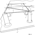
- FIG. 5 shows a perspective view of a concrete floor using multiple reinforcement structures 1, in accordance with some embodiments.
- Multiple poured concrete versions of column 5 that are cylindrical in length and circular or elliptical in cross section, may have their baes mounted on a concrete foundation 50 or on top of another concrete floor to form a multistory building for example.
- Two triangular floor slabs 10 with their hypotenuses adjacent and attached to each to form a rectangular floor surface that are placed and attached to four columns 5.
- Two of the four columns 5 diagonally opposite each attach to two respective corners C1 and C2 of the two triangular floor slabs 10 that form the rectangle.
- One of the same two of the four columns 5 also attach to a right angled corner of another adjacent triangular floor slabs 10 above the rectangle.
- a column 5 may attach in total to two ninety degree corners of two triangular floor slabs 10, two corners C1 of another two triangular floor slabs 10, and two corners C2 of yet another two triangular floor slabs 10.
- an even number of triangular floor slabs 10 may be connected together and further attached to triangular floor slabs 10 that run across the side of the multistory building to form a cantilever balcony for example.
- reinforcement structure 1 is constructed that includes circumferential beams B1 and B2, central ribs B3, and reinforcement bars 2 to produce a triangular circumferential beam or reinforcement structure 1.
- Circumferential beams B1 and B2 may be formed implemented in an open U box section or as enclosed box sections. Both open U box and enclosed box sections may be implemented in steel, stainless steel, aluminum, or carbon fibre.
- Corner C1 may be formed by welding or adhesively bonding one end of circumferential beam B1 to one of end of circumferential beam B2.
- the ninety degree (90°) angle corner of circumferential beam B2 may fabricated and welded or adhesively bonded together.
- Corner C2 may be formed by welding or adhesively bonding the other end of circumferential beam B1 to the other end of circumferential beam B2.
- plates 26 attach to the point of attachment by welding or adhesively bonding.
- the point of attachment may further include the means to attach pates 26 or 19 to column 5.
- anchor plate 22 attaches to both plates 26 and circumferential beams B2 and B1 and a similar arrangement is provided at corner C1.
- U bolts 25 attach to the horizontal portion of plates 26 that attach to circumferential beams B2 and B1 to form corners C1 and C2.
- U bolts 25 are utilized to enable a crane to lift reinforcement structure 1 or a concrete formed slab 10 using reinforcement structure 1 into position above columns 5.
- the lifting by the crane of reinforcement structure 1 or a concrete formed slab 10 is half of that would have to be lifted for a rectangular slab formed by use of two formed concrete slabs 10 joined together.
- Anchor plate 24 attaches to circumferential beam B2 at corner C2 and similar arrangement is provided at corner C1.
- multiple reinforcement bars 2 are attached to anchor plate 24 by multiple respective pocket formers 23b and wedges.
- Pocket formers 23b and wedges at corners C1 and C2 enable a tensile force to be applied and fixed across circumferential beam B2.
- the tensile force being applied by connection of a hydraulic jack to reinforcement bars 2 and its operation applied to reinforcement bars 2 that go through pocket formers 23b.
- pocket formers 23a and wedges are provided at corners C1 and C2 enable a tensile force to be applied and fixed across circumferential beam B1.
- anchor plates 22, 24 and 26 enables attachment of a triangular circumferential concrete beam perpendicular to column 5, attachment to another triangular circumferential beam, attachment to a walls of a building, and attachment to the shell of a building.
- central ribs B3, in a cross format connects horizontally between the hypotenuse and one side of circumferential beam B2 opposite corner C2.
- another central rib B3 located above the cross format connects by welding or adhesively bonding between the hypotenuse and one side of circumferential beam B2 opposite corner C2.
- central ribs B3, in the cross format connects vertically between the hypotenuse and the other side opposite of corner C1 of circumferential beam B2.
- another central rib B3 located to the right of the cross format connects between the hypotenuse and one side of circumferential beam B2 opposite corner C1.
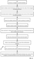
- Step 605 begins the process of the manufacture of a concrete slab 10 that includes the features of reinforcement structure 1 described above, to tensionally attach multiple reinforcing bars 2 between two corners C1 and C2 of reinforcement structure 1.
- the placing of the features of reinforcement structure 1 and the pouring of concrete 13 into mould 45 are performed offsite prior to transportation of the concrete slab 10 to a construction site.
- the placing (step 613) of the features of reinforcement structure 1 and the pouring (step 617) of concrete 13 into mould 45 may be performed in a factory, at a construction site or a mobile factory.
- the mobile factory may enable the fabrication of reinforcement structure 1, conduits 44, and the attachment of reinforcement mesh 3 to the bottom of mould 45 and the attachment of a second mesh 3 to the top of reinforcement structure 1 placed in mould 45 prior to pouring of concrete 13.
- Reinforcing bars 2 that are tensionally stressed following pouring and partial curing of concrete 13 are an example of the formation of a post-stressed concrete slab 10. Whereas, reinforcing bars 2 that are tensionally stressed prior to pouring and curing of concrete 13 are an example of the formation of a pre-stressed concrete slab 10.
- the tensile force applied to pocket formers 23b and 24a and the wedges used to maintain the tensile force around reinforcement structure 1 may be different for the formation of a pre-stressed concrete slab 10 or the formation of a post-stressed concrete slab 10 (step 619).
- Mould 45 may be constructed from steel, wood, carbon fibre, aluminum, and fiberglass.
- a casting pattern of mould 45 may further enable the routing and attachment of conduits 44 in the triangular concrete slab and the connection of conduits 44 in another adjacent triangular concrete slab another building element such as rebar cage 40.
- Re-bar cage 40 for example may be utilized to form a concrete vertical column attachable perpendicular to a triangular concrete slab.
- the concrete vertical column may include guides for centering rebar cage 40 around conduits 44, enable the routing of conduits 44 by a casting pattern enabled in the in the vertical column by the use of Styrofoam guides/ spacers 47 for example.
- the casting pattern in the vertical column enables the connection between the conduits 44 of the vertical column to connect to the conduits of a triangular concrete slab.
- reinforcing bars 2 may be housed in multiple conduits so that when concrete 13 is poured and partially sets around the conduits (step 617).
- the reinforcing bars are tensionally moveable between two corners C1 and C2 of the triangular circumferential beam formed by circumferential beams B2 and B1, where reinforcing bars 2 attach to the anchor plates 24 and anchor plates 22 respectively.
- one triangular reinforcement mesh 3 is placed in the bottom of mould 45.
- one of three rebar cages are constructed to surround the hypotenuse side formed by circumferential beam B1 and two rebar cages constructed to surround the sides formed by circumferential beam B2 to form a reinforcement structure.
- Each rebar cage is made up of longitudinal bars 42 that are normally distributed with equal spacing to form the outside of a rectangular column.
- Transverse reinforcing bars 43 are placed around and attached to longitudinal bars 42, with the longitudinal bars 42 and transverse reinforcing bars 43 being held together with ties, clamps, or, in special cases, with welds.
- Other components of a rebar cage may include guides for centering the rebar cage to encompass circumferential beams B1 and B2.
- the three rebar cages are attached to each other at the three corners of reinforcement structure 1 so that a triangular shaped concrete slab 10 may be subsequently formed.
- Central ribs B3 may or may not also be surrounded with similar rebar cages if required.
- conduits 44 may be used to house, protect and enable the run electric cables, gas and water lines to equipment housing 38 that may be attached or recessed into the underside for a formed triangular concrete slab prior to pouring of concrete 13 (step 617).
- Equipment housing 38 for example may be for an air conditioning unit that requires electricity supply and gas suction and blow lines or may be a lighting junction box.
- apertures 12 may also be utilized to enable conduits 44 to pass through into an area of another adjacent formed triangular concrete slab and other concrete structures that include similar conduits 44.
- the reinforcement structure fabricated at step 611 is placed into mould 45 on top of mesh placed into the bottom of mould 45 at step 609.
- a top reinforcement mesh 3 is attached on top of the reinforcement structure.
- concrete 13 is poured onto top mesh 3 and mould 45 to completely surround the reinforcement structure and concrete 13 is allowed to set.
- pocket formers 23b and wedges at corners C1 and C2 enable a tensile force to be applied and fixed across circumferential beam B2 encased with set concrete 13.
- the tensile force being applied by connection of a hydraulic jack to reinforcement bars 2 and its operation applied to reinforcement bars 2 that go through pocket formers 23b.
- pocket formers 23a and wedges are provided at corners C1 and C2 to enable a tensile force to be applied and fixed across circumferential beam B1 encased with set concrete 13.
- the tensile force being applied again by connection of a hydraulic jack to reinforcement bars 2 and its operation applied to reinforcement bars 2 that go through pocket formers 23a.
- the tensile stresses applied therefore, place the cross sectional area of reinforcement structure 1 filled with set concrete 13 to be held in compression around the perimeter of reinforcement structure 1.
- post-stressed concrete slab 10 (step 619) by utilization reinforcement structure 1, allows for greater adaptability to different types of foundations and ground conditions, making it suitable for a wide range of building sites. Attaching the floor structure on-site allows for more customization and adaptability to the existing structure or site condition.
- the modular design of post-stressed concrete slab 10 can also incorporate the necessary conduits 44 for electricity, gas, and water lines to connect together and between floors. Conduits 44 can be integrated into the pre-fabricated post-stressed concrete slab 10 to provide a seamless connection between floors and improving the efficiency of an infrastructure for a building.
- Columns 5 can be constructed between each post-stressed concrete slab 10, which also incorporate the necessary conduits 44 for the utilities of a building.
- the number and arrangement of columns 5 may play a crucial role in the stability of a building structure.
- Using two triangular shaped post-stressed concrete slab 10 on four columns 5 to form a rectangular floor surface may be generally better than a rectangular slab on the same four vertical columns. Because triangular shaped post-stressed concrete slabs 10 may have a more even distribution of weight across their support columns, which improves their stability. Whereas a rectangular slab supported by four vertical columns 5 concentrates the weight of the rectangular slab on the corners where the columns meet the rectangular slab, creating uneven pressure on columns 5, which can cause them to bow or bend over time.
- triangular shaped post-stressed concrete slabs 10 may distribute the weight more evenly across their support columns 5.
- the triangular shape of post-stressed concrete slabs 10, allows for a larger base of support, which helps to evenly distribute the weight across all four columns 5.
- the larger base of support creates a more stable floor surface that is less likely to experience bowing, bending, cracking, or breaking.
- using a triangular shaped post-stressed concrete slab 10 on three vertical columns 5 can provide even greater stability, especially in situations where one or more of the support columns 5 are shorter than the others. When using four vertical columns to support a rectangular slab, if one of the columns 5 is shorter than the others, it can cause the entire floor surface to wobble or become unstable.
- Pre-stressed concrete means cables or bars cables or bars that are placed and moveably attached around a perimeter of a re-enforcement structure that are stressed prior to pouring and curing of the concrete in a mould that houses the cables or bars of the re-enforcement structure.
- post-stressed concrete means cables or bars placed and moveably attached around a perimeter of a re-enforcement structure, and that are stressed following pouring and partial curing of the concrete in a mould that houses the cables or bars of the re-enforcement structure to form thereby a compressed concrete slab.
- composition or method may include additional ingredients and/or steps, but only if the additional ingredients and/or steps do not materially alter the basic and novel characteristics of the claimed composition or method.
- a compound or “at least one compound” may include a plurality of compounds, including mixtures thereof.
Landscapes
- Engineering & Computer Science (AREA)
- Architecture (AREA)
- Civil Engineering (AREA)
- Structural Engineering (AREA)
- Physics & Mathematics (AREA)
- Electromagnetism (AREA)
- Chemical & Material Sciences (AREA)
- Composite Materials (AREA)
- Rod-Shaped Construction Members (AREA)
- Reinforcement Elements For Buildings (AREA)
Applications Claiming Priority (1)
| Application Number | Priority Date | Filing Date | Title |
|---|---|---|---|
| IL304705A IL304705A (en) | 2023-07-24 | 2023-07-24 | Reinforcement structure for forming a triangular concrete floor or ceiling |
Publications (1)
| Publication Number | Publication Date |
|---|---|
| EP4497888A1 true EP4497888A1 (fr) | 2025-01-29 |
Family
ID=91969220
Family Applications (1)
| Application Number | Title | Priority Date | Filing Date |
|---|---|---|---|
| EP24190658.5A Withdrawn EP4497888A1 (fr) | 2023-07-24 | 2024-07-24 | Structure de renforcement pour former un plancher ou une dalle de plafond en béton triangulaire |
Country Status (4)
| Country | Link |
|---|---|
| US (1) | US20250034872A1 (fr) |
| EP (1) | EP4497888A1 (fr) |
| IL (1) | IL304705A (fr) |
| TW (1) | TW202513944A (fr) |
Citations (3)
| Publication number | Priority date | Publication date | Assignee | Title |
|---|---|---|---|---|
| US3195277A (en) * | 1957-06-27 | 1965-07-20 | Ceco Corp | Prestressed concrete slab construction |
| US5785904A (en) * | 1993-12-20 | 1998-07-28 | R.A.R. Consultants Ltd. | Method of securing and architectural finish element to a surface |
| US20210025164A1 (en) * | 2019-07-28 | 2021-01-28 | Shahabeddin Zaregarizi | Pre-stressed intersecting modular truss and concrete decking floor system |
Family Cites Families (8)
| Publication number | Priority date | Publication date | Assignee | Title |
|---|---|---|---|---|
| US1444806A (en) * | 1922-03-10 | 1923-02-13 | Soty Joseph | Floor construction for reenforced concrete |
| US3951085A (en) * | 1973-08-06 | 1976-04-20 | Johnson Don E | Floating structure arrangement |
| US4432175A (en) * | 1981-02-17 | 1984-02-21 | Smith Rodney I | Post-tensioned concrete slab |
| FR2603130B1 (fr) * | 1986-08-21 | 1988-11-10 | Framatome Sa | Radier pour enceinte de confinement de reacteur nucleaire |
| US5230191A (en) * | 1991-05-28 | 1993-07-27 | Paul Mayrand | Precast insulated concrete panel for prefabricated building structure |
| US5671573A (en) * | 1996-04-22 | 1997-09-30 | Board Of Regents, University Of Nebraska-Lincoln | Prestressed concrete joist |
| FI131659B1 (fi) * | 2020-06-12 | 2025-08-28 | Instmsto Cm Rakentajat Oy | Kaiderakenne ja kaiderakenteen käsittävä parveke |
| US12565769B2 (en) * | 2023-04-27 | 2026-03-03 | NJIP Holding Company LLC | Structural module, system, and method |
-
2023
- 2023-07-24 IL IL304705A patent/IL304705A/en unknown
-
2024
- 2024-07-24 EP EP24190658.5A patent/EP4497888A1/fr not_active Withdrawn
- 2024-07-24 US US18/782,053 patent/US20250034872A1/en active Pending
- 2024-07-24 TW TW113127618A patent/TW202513944A/zh unknown
Patent Citations (3)
| Publication number | Priority date | Publication date | Assignee | Title |
|---|---|---|---|---|
| US3195277A (en) * | 1957-06-27 | 1965-07-20 | Ceco Corp | Prestressed concrete slab construction |
| US5785904A (en) * | 1993-12-20 | 1998-07-28 | R.A.R. Consultants Ltd. | Method of securing and architectural finish element to a surface |
| US20210025164A1 (en) * | 2019-07-28 | 2021-01-28 | Shahabeddin Zaregarizi | Pre-stressed intersecting modular truss and concrete decking floor system |
Also Published As
| Publication number | Publication date |
|---|---|
| TW202513944A (zh) | 2025-04-01 |
| IL304705A (en) | 2025-02-01 |
| US20250034872A1 (en) | 2025-01-30 |
Similar Documents
| Publication | Publication Date | Title |
|---|---|---|
| US8161691B2 (en) | Precast composite structural floor system | |
| US9340975B2 (en) | Method of casting in-situ ferrocement ribbed slab with spliced rack and suspended formwork | |
| EP1007799B1 (fr) | Panneau de construction à utiliser dans la construction de bâtiments | |
| CN103797197A (zh) | 预铸整体式墙与楼板的建筑结构 | |
| CN102449247A (zh) | 半预制楼板及使用该半预制楼板的板材的构筑方法 | |
| CN115613751A (zh) | 一种芯模与楼盖底板整体预制的模块化空心楼盖 | |
| US20090301011A1 (en) | Reinforced concrete ceiling and process for the manufacture thereof | |
| CN110905112A (zh) | 一种预制型钢混凝土叠合板及施工工艺 | |
| CN210369292U (zh) | 装配式建筑现浇叠合模壳一体化结构 | |
| CN104870724B (zh) | 自承载均质双轴混凝土层的系统和方法 | |
| CN111926912B (zh) | 适用于装配式建筑的整体预制阳台、连接节点及制造方法 | |
| CN212613003U (zh) | 一种适用于装配式建筑的整体预制阳台、连接节点 | |
| KR102332143B1 (ko) | 물류 구조물 시공을 위한 pc 슬래브와 pc 거더의 결합 시공 구조 | |
| JP7554660B2 (ja) | 基礎梁の構築方法 | |
| US20250034872A1 (en) | Reinforcement structure for forming a triangular concrete floor or ceiling slab | |
| CN102216540B (zh) | 预应力板元件 | |
| CN113957993A (zh) | 一种装配体系以及其施工方法 | |
| KR200178874Y1 (ko) | 조립식 pc콘크리트 벽체판넬 | |
| CN216305080U (zh) | 多钢筋桁架混凝土翼缘组合预应力混凝土叠合板 | |
| CN112282164B (zh) | 一种轻质叠合楼板结构及其施工方法 | |
| CN101454519A (zh) | 面状的混凝土支承结构和用于制造该混凝土支承结构的方法 | |
| JP3358047B2 (ja) | 大型床版の製造方法及び構造体の鉄筋コンクリート造の傾斜床の施工方法 | |
| CN203475599U (zh) | 耐震、预制的钢管剪力墙混合结构建筑物 | |
| RU2713826C2 (ru) | Способ изготовления сборно-монолитных железобетонных опирающихся по контуру плит перекрытий с круглыми пустотами с применением неизвлекаемых картонно-полиэтиленовых пустотообразователей | |
| CN219343709U (zh) | 一种立体空间网架叠合板 |
Legal Events
| Date | Code | Title | Description |
|---|---|---|---|
| PUAI | Public reference made under article 153(3) epc to a published international application that has entered the european phase |
Free format text: ORIGINAL CODE: 0009012 |
|
| STAA | Information on the status of an ep patent application or granted ep patent |
Free format text: STATUS: REQUEST FOR EXAMINATION WAS MADE |
|
| 17P | Request for examination filed |
Effective date: 20240724 |
|
| AK | Designated contracting states |
Kind code of ref document: A1 Designated state(s): AL AT BE BG CH CY CZ DE DK EE ES FI FR GB GR HR HU IE IS IT LI LT LU LV MC ME MK MT NL NO PL PT RO RS SE SI SK SM TR |
|
| STAA | Information on the status of an ep patent application or granted ep patent |
Free format text: STATUS: THE APPLICATION IS DEEMED TO BE WITHDRAWN |
|
| 18D | Application deemed to be withdrawn |
Effective date: 20250730 |