EP4497899A1 - Schliessblech - Google Patents
Schliessblech Download PDFInfo
- Publication number
- EP4497899A1 EP4497899A1 EP24181100.9A EP24181100A EP4497899A1 EP 4497899 A1 EP4497899 A1 EP 4497899A1 EP 24181100 A EP24181100 A EP 24181100A EP 4497899 A1 EP4497899 A1 EP 4497899A1
- Authority
- EP
- European Patent Office
- Prior art keywords
- striker
- retaining element
- seat
- receiving body
- locks according
- Prior art date
- Legal status (The legal status is an assumption and is not a legal conclusion. Google has not performed a legal analysis and makes no representation as to the accuracy of the status listed.)
- Granted
Links
Images


Classifications
-
- E—FIXED CONSTRUCTIONS
- E05—LOCKS; KEYS; WINDOW OR DOOR FITTINGS; SAFES
- E05B—LOCKS; ACCESSORIES THEREFOR; HANDCUFFS
- E05B9/00—Lock casings or latch-mechanism casings ; Fastening locks or fasteners or parts thereof to the wing
- E05B9/08—Fastening locks or fasteners or parts thereof, e.g. the casings of latch-bolt locks or cylinder locks to the wing
- E05B9/082—Fastening locks or fasteners or parts thereof, e.g. the casings of latch-bolt locks or cylinder locks to the wing with concealed screws
-
- E—FIXED CONSTRUCTIONS
- E05—LOCKS; KEYS; WINDOW OR DOOR FITTINGS; SAFES
- E05B—LOCKS; ACCESSORIES THEREFOR; HANDCUFFS
- E05B17/00—Accessories in connection with locks
- E05B17/0041—Damping means
-
- E—FIXED CONSTRUCTIONS
- E05—LOCKS; KEYS; WINDOW OR DOOR FITTINGS; SAFES
- E05B—LOCKS; ACCESSORIES THEREFOR; HANDCUFFS
- E05B15/00—Other details of locks; Parts for engagement by bolts of fastening devices
- E05B15/02—Striking-plates; Keepers; Bolt staples; Escutcheons
- E05B15/0205—Striking-plates, keepers, staples
-
- E—FIXED CONSTRUCTIONS
- E05—LOCKS; KEYS; WINDOW OR DOOR FITTINGS; SAFES
- E05B—LOCKS; ACCESSORIES THEREFOR; HANDCUFFS
- E05B47/00—Operating or controlling locks or other fastening devices by electric or magnetic means
- E05B47/0046—Electric or magnetic means in the striker or on the frame; Operating or controlling the striker plate
-
- E—FIXED CONSTRUCTIONS
- E05—LOCKS; KEYS; WINDOW OR DOOR FITTINGS; SAFES
- E05C—BOLTS OR FASTENING DEVICES FOR WINGS, SPECIALLY FOR DOORS OR WINDOWS
- E05C19/00—Other devices specially designed for securing wings, e.g. with suction cups
- E05C19/16—Devices holding the wing by magnetic or electromagnetic attraction
- E05C19/163—Devices holding the wing by magnetic or electromagnetic attraction a movable bolt being held in the striker by a permanent magnet
Definitions
- the present invention relates to a striker for locks.
- the striker according to the invention falls within the technical field of the production and marketing of strikers, in particular magnetic type strikers, for locks intended for closing fixtures, such as doors and windows, made of a variety of materials, e.g., aluminium, aluminium-wood, wood and PVC.
- the striker according to the invention finds particular and advantageous use when installed on hollow-type frame profiles, such as frames made of an aluminium alloy.
- strikers is known in the technical reference field for making locks intended for closing and/or opening fixtures, in particular doors and windows, installed in many types of buildings, such as offices, hotels, commercial shops, houses, flats and still others.
- the strikers of known type for locks typically comprise a body insertable into a housing seat previously obtained on a fixture, in particular on the frame profile of a door or window.
- the body typically comprises multiple openings, in particular holes, adapted to receive fixing means, in particular threaded, such as screws or the like, for fixing the striker to the profile of the frame.
- the body further comprises a plurality of compartments, adapted to receive opening/closing members, in particular a member called a latch in the technical jargon of the field (e.g., of the magnetic or mechanical type), and sliders movable by the aforesaid fixing means to secure the striker in the seat of the frame.
- opening/closing members in particular a member called a latch in the technical jargon of the field (e.g., of the magnetic or mechanical type)
- sliders movable by the aforesaid fixing means to secure the striker in the seat of the frame.
- the main drawback lies in the fact that the strikers of known type for locks are difficult to assemble and disassemble from a seat of a door or window frame, e.g., in order to carry out maintenance and/or adjustment and/or inspection operations of the door or window itself.
- such fixing means and the movable sliders risk falling inside the hollow profile of the frame, without the possibility of recovering them.
- a further drawback lies in the fact that the strikers of known type for locks are aesthetically unattractive.
- such strikers have fixing means (i.e., screws or the like) visible to an operator, in particular such fixing means are disposed, in use, at the front face of the striker itself. This makes the door or window as a whole aesthetically unattractive. Therefore, the strikers of known type require covering elements intended to cover the aforesaid fixing means. This leads to an increase in the number of components required to complete the striker and thus greater construction and logistical complexity.
- the technical task of the present invention is to propose a striker for locks which allows to overcome, at least in part, the above-mentioned drawbacks of the prior art.
- an object of the present invention is to provide a striker for locks which is simple and reliable to assemble and disassemble on a frame profile of a door or window, even by a non-specialist operator.
- a further object of the present invention is to provide a striker for locks particularly suitable for frames with a hollow profile, such as aluminium alloy frames.
- Another object of the present invention is to propose a striker for locks capable of allowing a reliable installation while allowing aesthetic effects to be achieved.
- the striker 10 finds particular application in the technical field of manufacturing and marketing locks, in particular of the magnetic type, intended to be mounted in a profile, in particular internally hollow, of a door or window frame. More specifically, such a profile is in particular made of an aluminium alloy, e.g., by means of an extrusion or drawing process or the like.
- the striker according to the invention can also be used on profiles made of wood or PVC, without thereby falling outside the scope of protection.
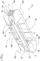
- the striker 10 for locks comprises a receiving body 20.
- the receiving body 20 extends along a longitudinal extension direction, between a first end 21a and a second end 21b.
- the receiving body 20 has a cavity 20" formed on a front face 20a adapted to receive a closure member, commonly referred to as a "latch” in the technical jargon of the field and preferably of the magnetic type (not illustrated in the attached figures), along an insertion direction Z.
- the receiving body 20 also has a lateral surface 20b.
- the cavity 20" is defined by two lateral walls disposed facing each other and extending substantially parallel to the extension direction of the body 20, and by two head walls facing each other and extending substantially orthogonal to the two lateral walls.
- the two lateral walls and the two head walls are connected to each other.
- the cavity 20" is also defined by a bottom wall 29a (introduced and described in more detail below) mechanically connected to the two lateral walls and to the two head walls.
- the striker 10 further comprises a retaining element 30 positioned in a seat 22 of the receiving body 20.
- the seat 22 is preferably obtained at the first end 20a or preferably at the second end 20b of the receiving body 20.
- the seat 22 has a substantially compartmentalised, i.e., substantially partially closed, shape. That is, as illustrated in figure 4 , the seat 22 essentially defines a guiding corridor which delimits, at least partially, the direction along which the retaining element 30 can move.
- the retaining element 30 is movable between an extracted position, corresponding to an engagement configuration in which the striker 10 is secured in a seat of a frame (not illustrated in the attached figures), and a retracted position, corresponding to a release configuration in which the striker 10 is extractable from the seat itself.
- the retaining element 30 comprises at least one slider slidably disposed in the seat 22 of the receiving body 20, and movable between the engagement configuration and the release configuration along a direction of movement Y that is transverse, preferably orthogonal, to the insertion direction Z.
- the receiving body 20 extends along a longitudinal extension direction that is substantially parallel to the direction of movement Y.
- the cavity 20" and the seat 22 of the receiving body 20 are disposed substantially aligned with each other, in particular they are intercepted by the direction of movement Y at the respective centreline.
- the retaining element 30 preferably comprises two sliders, in particular a first slider and a second slider.
- the first slider is preferably substantially the same as the second slider.
- the first slider and second the slider are interchangeable in the respective locations 22.
- each slider is slidingly disposed in a respective seat 22 obtained in the receiving body 20 and movable between the engagement configuration and the release configuration along a respective direction of movement Y that is transverse, preferably orthogonal, to the insertion direction Z.
- the sliders are disposed on opposite sides of the receiving body 20 relative to the cavity 20".
- a first slider is insertable into a seat 22 disposed at the first end 21a
- a second slider is insertable into a seat 22 opposite the previous seat and disposed at the second end 20b.
- the striker 10 comprises an adjustment member 50 insertable into said receiving body 20 and operatively associated with said retaining element 30.
- the adjustment member 50 is configured to be actuatable from inside the cavity 20" along a direction transverse to the insertion direction Z, so that the retaining element 30 is activated along a direction of movement Y transverse to the insertion direction Z.
- the striker 10 is free of visible adjustment members.
- the front face 20a is therefore free of discontinuities and substantially planar on its extension. That is, such a front face 20a is devoid of any machining, e.g., holes, seats, cavities or the like, intended to receive fixing elements, such as screws or the like. This allows to obtain an aesthetically pleasing striker for locks 10.
- the striker 10 for locks further comprises arresting means 21, 31 interposed between the retaining element 30 and the receiving body 20 to limit a movement of the retaining element 30 along a predetermined stroke so as to avoid the detachment of the retaining element 30 from the receiving body 20 when the retaining element 30 switches between the retracted position and the extracted position.
- the arresting means 21, 31 essentially define a limit-stop barrier, so as to prevent a movement beyond the limit defined by the barrier itself of the retaining member 30.
- the retaining member 30 remains engaged with the receiving body 20 during an assembly or disassembly operation of the striker in a seat.
- the risk is avoided of the retaining element 30 exiting from the receiving body 20, and thus the element 30 itself falling, e.g., inside the seat of the hollow profile of the frame.
- the arresting means 21, 31 are directly obtained on the receiving body 20 and on the retaining element 30, respectively.
- the arresting means 21, 31 are obtained in a single piece on the receiving body 20 and on the retaining element 30, respectively.
- the striker 10 is simple and inexpensive as it does not require any additional fixing means, such as screws, rivets or the like, to fix the aforesaid arresting means 21, 31 on the body 20 and on the retaining element 30, respectively.
- the arresting means 21, 31 comprise an abutment element associated with the retaining element 30 and a corresponding stop member integral with the seat 22 of the receiving body 20 so as to define a limit stop configured to abut against the abutment element.
- the abutment element is preferably tooth-shaped, in particular it has a curved portion R, preferably connected, facing outwards from the cavity 20" of the body 20, and a first planar operating surface, opposite the curved portion R.
- the stop member is barrier-shaped, in particular it has a second planar operating surface that is substantially parallel to the corresponding first planar operating surface of the abutment element, and an inclined surface opposite the second planar operating surface.
- the arresting means 21, 31 are configured to enter into abutment by means of a contact between the first operating surface and the second operating surface.
- such contact is of the interference type.
- the curved portion R and the inclined surface allow a simple and quick snapping movement of the retaining element 30 into the corresponding seat 22 (as described in more detail below).
- At least one of the abutment element and the stop member is made of a deformable material to enable the retaining element 30 to be snap fitted into the seat 22 of the receiving body 20.
- the adjustment member 50 is actuatable, preferably by means of a wrench, so as to move the retaining element 30 along the direction of movement Y that is transverse to the insertion direction Z.
- the adjustment member 50 and the retaining element 30 define a preferably threaded coupling of the screw-nut type.
- the adjustment member 50 comprises a screw of the hexagon socket countersunk head type, and the retaining element 30 has a threaded hole, preferably through, configured to mechanically couple with the screw.
- the adjustment member 50 has a nominal thread size selectable in the range between M3 and M5, preferably M4.
- the receiving body 20 comprises a first sliding guide 25 obtained on the lateral surface 20b and configured to receive the adjustment member 50 (i.e., the hexagon socket countersunk head screw).
- the adjustment member 50 i.e., the hexagon socket countersunk head screw.
- the receiving body 20 comprises a second sliding guide 25 obtained on the lateral surface 20b and configured to receive a second adjustment member 50.
- the first sliding guide 25 and the second sliding guide 25 are substantially equal to each other.
- first sliding guide 25 and the second sliding guide 25 are obtained on the same face of the lateral surface 20b of the receiving body 20.
- the insertion of the adjustment members 50 into the aforesaid first and second sliding guides 25 occurs on the same side of the lateral surface 20b.
- This is advantageous in the particular case of the assembly of the striker 10 by means of automatic systems, for example robots of the anthropomorphic type or the like, since the striker 10, once oriented in accordance with the face on which the first and second sliding guides 25 are obtained, does not need to be moved, in particular rotated substantially by 180°, to insert the adjustment members 50 into the respective sliding guides 25.
- each sliding guide 25 is preferably shaped to allow a customised insertion of the adjustment member 50.
- first sliding guide 25 and the second sliding guide 25 have a shape which essentially replicates the shape of a longitudinal section of the adjustment member, as illustrated in figures 2 and 4 .
- the adjustment member 50 remains housed in the first and second sliding guides without running the risk of exiting.
- the first sliding guide 25 and the second sliding guide 25 extend along respective housing directions S that are substantially orthogonal to the direction of movement Y of the adjustment members 50 and to the insertion direction Z.
- the receiving body 20 has a through opening 28 which internally faces the cavity 20" of the closure member.
- the opening 28 is configured to put the cavity 20" in communication with the seat 22 so as to enable access (e.g., by means of the wrench described above) to the first adjustment member 50.
- the receiving body 20 has two openings 28, preferably substantially equal to each other and disposed facing each other, in particular one opening 28 is disposed at the first end 20a and a second opening 28 is disposed at the second end 20b of the receiving body 20.
- the two openings 28 are preferably holes.
- the receiving body 20 comprises a compartment 29 adapted to receive a magnetic closure element, said compartment 29 is adjacent to the cavity 20" and separated therefrom by the bottom wall 29a.
- the retaining element 30 and/or the receiving body 20 are made of a material selectable from: a polymeric material or preferably a fibre-reinforced polymeric material.
- the receiving body 20 and/or the retaining element 30 can preferably be made of a metal material, e.g., steel or an aluminium alloy.
- the seat 22 is obtained on the lateral surface 20b and is positioned below an edge of the front face 20a.
- the front face 20a is substantially free of discontinuities, such as holes, openings, concavities or the like. This allows to give the front surface 20a and consequently the receiving body 20 of the striker 10 a pleasing aesthetic effect.
- the retaining element 30 has an active sawtooth-shaped portion 30a for engaging the seat of the frame.
- a sawtooth shape allows to obtain a better grip between the retaining element 30 and a corresponding surface of the seat of the frame.
- FIG 4 shows an exploded view of the striker 10 for locks, in particular, an operator takes an adjustment member 50 and inserts it along the sliding guide 25 so as to dispose it inside the receiving body 20, substantially aligned along the direction of movement Y.
- the operator takes a retaining element 30 and screws it in manually by a stroke so that it can be gripped with the adjustment member 50.
- the operator takes a wrench, in particular a male key, and rotates the adjustment member 50 therewith so as to move the retaining member 30 along the threaded stem of the adjustment member 50, i.e., along the direction of movement Y.
- a snap-fitting of the retaining element 30 in the seat 22 occurs.
- At least one of the retaining element 30 and/or the receiving body 20 is made of a deformable material, in particular elastic, as specified above.
- the striker 10 can be inserted into the seat of the frame and fixed therein by reversing the direction of rotation of the adjustment member 50, so as to move the retaining element 30 outwards, i.e., away from the cavity 20", and engage the surface 30a against a corresponding surface from the seat of the frame.
- the retaining element 30 cannot travel a stroke beyond that defined by the contact between the first and second planar operating surface.
- such surfaces define a planar contact, in particular substantially orthogonal to the direction of movement Y. This prevents a decoupling of the retaining element 30 from the adjustment member, and thus a detachment of the retaining element 30 itself from the seat 22 of the receiving body 20.
Landscapes
- Engineering & Computer Science (AREA)
- Mechanical Engineering (AREA)
- Physics & Mathematics (AREA)
- Electromagnetism (AREA)
- Lock And Its Accessories (AREA)
- Seats For Vehicles (AREA)
Applications Claiming Priority (1)
| Application Number | Priority Date | Filing Date | Title |
|---|---|---|---|
| IT102023000015915A IT202300015915A1 (it) | 2023-07-27 | 2023-07-27 | “incontro per serrature” |
Publications (2)
| Publication Number | Publication Date |
|---|---|
| EP4497899A1 true EP4497899A1 (de) | 2025-01-29 |
| EP4497899B1 EP4497899B1 (de) | 2025-11-26 |
Family
ID=88413907
Family Applications (1)
| Application Number | Title | Priority Date | Filing Date |
|---|---|---|---|
| EP24181100.9A Active EP4497899B1 (de) | 2023-07-27 | 2024-06-10 | Schliessblech |
Country Status (4)
| Country | Link |
|---|---|
| EP (1) | EP4497899B1 (de) |
| CN (1) | CN119373366A (de) |
| ES (1) | ES3063078T3 (de) |
| IT (1) | IT202300015915A1 (de) |
Citations (3)
| Publication number | Priority date | Publication date | Assignee | Title |
|---|---|---|---|---|
| WO2011030291A1 (en) * | 2009-09-08 | 2011-03-17 | Alban Giacomo - S.P.A. | Strike plate for spring-latch locks, particularly with a magnetic spring- latch |
| EP2248968B1 (de) * | 2009-04-28 | 2017-10-25 | Alban Giacomo S.p.A. | Schliessblech für Federriegelschlösser, insbesondere mit einem magnetischen Federriegel |
| EP2878748B1 (de) * | 2013-11-28 | 2019-06-26 | Alban Giacomo S.p.A. | Schließblech für Fallenschlösser, bei denen ein Federriegel in eine Schließbohrung einrastet, insbesondere mit einem magnetischen Federriegel |
-
2023
- 2023-07-27 IT IT102023000015915A patent/IT202300015915A1/it unknown
-
2024
- 2024-06-10 ES ES24181100T patent/ES3063078T3/es active Active
- 2024-06-10 EP EP24181100.9A patent/EP4497899B1/de active Active
- 2024-06-25 CN CN202410823857.7A patent/CN119373366A/zh active Pending
Patent Citations (3)
| Publication number | Priority date | Publication date | Assignee | Title |
|---|---|---|---|---|
| EP2248968B1 (de) * | 2009-04-28 | 2017-10-25 | Alban Giacomo S.p.A. | Schliessblech für Federriegelschlösser, insbesondere mit einem magnetischen Federriegel |
| WO2011030291A1 (en) * | 2009-09-08 | 2011-03-17 | Alban Giacomo - S.P.A. | Strike plate for spring-latch locks, particularly with a magnetic spring- latch |
| EP2878748B1 (de) * | 2013-11-28 | 2019-06-26 | Alban Giacomo S.p.A. | Schließblech für Fallenschlösser, bei denen ein Federriegel in eine Schließbohrung einrastet, insbesondere mit einem magnetischen Federriegel |
Also Published As
| Publication number | Publication date |
|---|---|
| EP4497899B1 (de) | 2025-11-26 |
| IT202300015915A1 (it) | 2025-01-27 |
| ES3063078T3 (en) | 2026-04-15 |
| CN119373366A (zh) | 2025-01-28 |
Similar Documents
| Publication | Publication Date | Title |
|---|---|---|
| US7404306B2 (en) | Multi-point door lock and offset extension bolt assembly | |
| EP2774518B1 (de) | Duschtüranordnung | |
| US4655025A (en) | Edge rail for a window pane, in particular an all-glass door | |
| HU222379B1 (hu) | Zárszerkezet, valamint ilyen zárszerkezettel ellátott zárrendszer | |
| WO2022167230A1 (en) | Improved inspection trapdoor | |
| ITTO20070780A1 (it) | Sistema di sicurezza anti-scasso per serramenti | |
| US6270129B1 (en) | Locking device for sliding doors, windows and the like | |
| EP4497899A1 (de) | Schliessblech | |
| US6050114A (en) | Latch assembly of padlock for sliding doors | |
| US10895101B1 (en) | Adaptable fenestration frame members and methods | |
| EP3306019B1 (de) | Universelle mehrpunktschlossanordnung | |
| GB2567576B (en) | Multipoint lock with adjustable connecting rod linkage | |
| KR20090039150A (ko) | 안전부재가 장착된 미닫이문 | |
| EP1743996B1 (de) | Betätigungseinheit für Türe oder Fenster | |
| GB2476486A (en) | A block member for locating on the shaft of a locking pin of a multipoint lock | |
| KR920002120B1 (ko) | 여닫이문 자물쇠 | |
| CZ20014108A3 (cs) | Kování s tyčemi závory pro okno nebo dveře | |
| AU2006100650A4 (en) | A Sliding Door or Window Sash Having Square Cut Members and Corner Connectors | |
| EP3048222B1 (de) | Schliessblech für eine schlossfalle und anordnung aus schliessblech und schloss mit einer falle | |
| EP1479862A2 (de) | Betätigungsvorrichtung für Türen und Fenster | |
| AU2010201433B2 (en) | A Sliding Door or Window Sash Having Square Cut Members and Corner Connectors | |
| KR102146167B1 (ko) | 도어의 가공홈 형성용 트리머 조기대 | |
| KR102421686B1 (ko) | 탈거방지를 위한 조립식 결로방지패드 및 이를 포함하는 창호브라켓 | |
| SK141991A3 (en) | Boarding | |
| KR200252525Y1 (ko) | 가구용 손잡이 |
Legal Events
| Date | Code | Title | Description |
|---|---|---|---|
| PUAI | Public reference made under article 153(3) epc to a published international application that has entered the european phase |
Free format text: ORIGINAL CODE: 0009012 |
|
| STAA | Information on the status of an ep patent application or granted ep patent |
Free format text: STATUS: THE APPLICATION HAS BEEN PUBLISHED |
|
| AK | Designated contracting states |
Kind code of ref document: A1 Designated state(s): AL AT BE BG CH CY CZ DE DK EE ES FI FR GB GR HR HU IE IS IT LI LT LU LV MC ME MK MT NL NO PL PT RO RS SE SI SK SM TR |
|
| STAA | Information on the status of an ep patent application or granted ep patent |
Free format text: STATUS: REQUEST FOR EXAMINATION WAS MADE |
|
| 17P | Request for examination filed |
Effective date: 20250127 |
|
| P01 | Opt-out of the competence of the unified patent court (upc) registered |
Free format text: CASE NUMBER: APP_5640/2025 Effective date: 20250203 |
|
| GRAP | Despatch of communication of intention to grant a patent |
Free format text: ORIGINAL CODE: EPIDOSNIGR1 |
|
| STAA | Information on the status of an ep patent application or granted ep patent |
Free format text: STATUS: GRANT OF PATENT IS INTENDED |
|
| RIC1 | Information provided on ipc code assigned before grant |
Ipc: E05B 9/08 20060101AFI20250612BHEP Ipc: E05B 15/02 20060101ALI20250612BHEP Ipc: E05B 47/00 20060101ALI20250612BHEP Ipc: E05C 19/16 20060101ALI20250612BHEP |
|
| INTG | Intention to grant announced |
Effective date: 20250627 |
|
| GRAS | Grant fee paid |
Free format text: ORIGINAL CODE: EPIDOSNIGR3 |
|
| GRAA | (expected) grant |
Free format text: ORIGINAL CODE: 0009210 |
|
| STAA | Information on the status of an ep patent application or granted ep patent |
Free format text: STATUS: THE PATENT HAS BEEN GRANTED |
|
| AK | Designated contracting states |
Kind code of ref document: B1 Designated state(s): AL AT BE BG CH CY CZ DE DK EE ES FI FR GB GR HR HU IE IS IT LI LT LU LV MC ME MK MT NL NO PL PT RO RS SE SI SK SM TR |
|
| REG | Reference to a national code |
Ref country code: CH Ref legal event code: F10 Free format text: ST27 STATUS EVENT CODE: U-0-0-F10-F00 (AS PROVIDED BY THE NATIONAL OFFICE) Effective date: 20251126 Ref country code: GB Ref legal event code: FG4D |
|
| REG | Reference to a national code |
Ref country code: DE Ref legal event code: R096 Ref document number: 602024001401 Country of ref document: DE |
|
| REG | Reference to a national code |
Ref country code: IE Ref legal event code: FG4D |
|
| REG | Reference to a national code |
Ref country code: NL Ref legal event code: MP Effective date: 20251126 |
|
| REG | Reference to a national code |
Ref country code: LT Ref legal event code: MG9D |
|
| PG25 | Lapsed in a contracting state [announced via postgrant information from national office to epo] |
Ref country code: NO Free format text: LAPSE BECAUSE OF FAILURE TO SUBMIT A TRANSLATION OF THE DESCRIPTION OR TO PAY THE FEE WITHIN THE PRESCRIBED TIME-LIMIT Effective date: 20260226 |
|
| PG25 | Lapsed in a contracting state [announced via postgrant information from national office to epo] |
Ref country code: FI Free format text: LAPSE BECAUSE OF FAILURE TO SUBMIT A TRANSLATION OF THE DESCRIPTION OR TO PAY THE FEE WITHIN THE PRESCRIBED TIME-LIMIT Effective date: 20251126 Ref country code: AT Free format text: LAPSE BECAUSE OF FAILURE TO SUBMIT A TRANSLATION OF THE DESCRIPTION OR TO PAY THE FEE WITHIN THE PRESCRIBED TIME-LIMIT Effective date: 20251126 Ref country code: HR Free format text: LAPSE BECAUSE OF FAILURE TO SUBMIT A TRANSLATION OF THE DESCRIPTION OR TO PAY THE FEE WITHIN THE PRESCRIBED TIME-LIMIT Effective date: 20251126 |
|
| REG | Reference to a national code |
Ref country code: ES Ref legal event code: FG2A Ref document number: 3063078 Country of ref document: ES Kind code of ref document: T3 Effective date: 20260415 Ref country code: AT Ref legal event code: MK05 Ref document number: 1861192 Country of ref document: AT Kind code of ref document: T Effective date: 20251126 |
|
| PG25 | Lapsed in a contracting state [announced via postgrant information from national office to epo] |
Ref country code: NL Free format text: LAPSE BECAUSE OF FAILURE TO SUBMIT A TRANSLATION OF THE DESCRIPTION OR TO PAY THE FEE WITHIN THE PRESCRIBED TIME-LIMIT Effective date: 20251126 |
|
| PG25 | Lapsed in a contracting state [announced via postgrant information from national office to epo] |
Ref country code: RS Free format text: LAPSE BECAUSE OF FAILURE TO SUBMIT A TRANSLATION OF THE DESCRIPTION OR TO PAY THE FEE WITHIN THE PRESCRIBED TIME-LIMIT Effective date: 20260226 |
|
| PG25 | Lapsed in a contracting state [announced via postgrant information from national office to epo] |
Ref country code: IS Free format text: LAPSE BECAUSE OF FAILURE TO SUBMIT A TRANSLATION OF THE DESCRIPTION OR TO PAY THE FEE WITHIN THE PRESCRIBED TIME-LIMIT Effective date: 20260326 |
|
| PG25 | Lapsed in a contracting state [announced via postgrant information from national office to epo] |
Ref country code: PT Free format text: LAPSE BECAUSE OF FAILURE TO SUBMIT A TRANSLATION OF THE DESCRIPTION OR TO PAY THE FEE WITHIN THE PRESCRIBED TIME-LIMIT Effective date: 20260326 |
|
| PG25 | Lapsed in a contracting state [announced via postgrant information from national office to epo] |
Ref country code: PL Free format text: LAPSE BECAUSE OF FAILURE TO SUBMIT A TRANSLATION OF THE DESCRIPTION OR TO PAY THE FEE WITHIN THE PRESCRIBED TIME-LIMIT Effective date: 20251126 |
|
| PG25 | Lapsed in a contracting state [announced via postgrant information from national office to epo] |
Ref country code: LV Free format text: LAPSE BECAUSE OF FAILURE TO SUBMIT A TRANSLATION OF THE DESCRIPTION OR TO PAY THE FEE WITHIN THE PRESCRIBED TIME-LIMIT Effective date: 20251126 |