EP4497908A2 - Tête de forage et système de forage incorporè - Google Patents
Tête de forage et système de forage incorporè Download PDFInfo
- Publication number
- EP4497908A2 EP4497908A2 EP24219519.6A EP24219519A EP4497908A2 EP 4497908 A2 EP4497908 A2 EP 4497908A2 EP 24219519 A EP24219519 A EP 24219519A EP 4497908 A2 EP4497908 A2 EP 4497908A2
- Authority
- EP
- European Patent Office
- Prior art keywords
- drill head
- extension arm
- base body
- disengaged position
- head according
- Prior art date
- Legal status (The legal status is an assumption and is not a legal conclusion. Google has not performed a legal analysis and makes no representation as to the accuracy of the status listed.)
- Granted
Links
Images


Classifications
-
- E—FIXED CONSTRUCTIONS
- E21—EARTH OR ROCK DRILLING; MINING
- E21B—EARTH OR ROCK DRILLING; OBTAINING OIL, GAS, WATER, SOLUBLE OR MELTABLE MATERIALS OR A SLURRY OF MINERALS FROM WELLS
- E21B10/00—Drill bits
- E21B10/26—Drill bits with leading portion, i.e. drill bits with a pilot cutter; Drill bits for enlarging the borehole, e.g. reamers
- E21B10/32—Drill bits with leading portion, i.e. drill bits with a pilot cutter; Drill bits for enlarging the borehole, e.g. reamers with expansible cutting tools
- E21B10/322—Drill bits with leading portion, i.e. drill bits with a pilot cutter; Drill bits for enlarging the borehole, e.g. reamers with expansible cutting tools cutter shifted by fluid pressure
-
- E—FIXED CONSTRUCTIONS
- E21—EARTH OR ROCK DRILLING; MINING
- E21B—EARTH OR ROCK DRILLING; OBTAINING OIL, GAS, WATER, SOLUBLE OR MELTABLE MATERIALS OR A SLURRY OF MINERALS FROM WELLS
- E21B10/00—Drill bits
- E21B10/26—Drill bits with leading portion, i.e. drill bits with a pilot cutter; Drill bits for enlarging the borehole, e.g. reamers
- E21B10/32—Drill bits with leading portion, i.e. drill bits with a pilot cutter; Drill bits for enlarging the borehole, e.g. reamers with expansible cutting tools
- E21B10/327—Drill bits with leading portion, i.e. drill bits with a pilot cutter; Drill bits for enlarging the borehole, e.g. reamers with expansible cutting tools the cutter being pivoted about a longitudinal axis
-
- E—FIXED CONSTRUCTIONS
- E21—EARTH OR ROCK DRILLING; MINING
- E21B—EARTH OR ROCK DRILLING; OBTAINING OIL, GAS, WATER, SOLUBLE OR MELTABLE MATERIALS OR A SLURRY OF MINERALS FROM WELLS
- E21B12/00—Accessories for drilling tools
-
- E—FIXED CONSTRUCTIONS
- E21—EARTH OR ROCK DRILLING; MINING
- E21B—EARTH OR ROCK DRILLING; OBTAINING OIL, GAS, WATER, SOLUBLE OR MELTABLE MATERIALS OR A SLURRY OF MINERALS FROM WELLS
- E21B7/00—Special methods or apparatus for drilling
- E21B7/28—Enlarging drilled holes, e.g. by counterboring
-
- Y—GENERAL TAGGING OF NEW TECHNOLOGICAL DEVELOPMENTS; GENERAL TAGGING OF CROSS-SECTIONAL TECHNOLOGIES SPANNING OVER SEVERAL SECTIONS OF THE IPC; TECHNICAL SUBJECTS COVERED BY FORMER USPC CROSS-REFERENCE ART COLLECTIONS [XRACs] AND DIGESTS
- Y02—TECHNOLOGIES OR APPLICATIONS FOR MITIGATION OR ADAPTATION AGAINST CLIMATE CHANGE
- Y02E—REDUCTION OF GREENHOUSE GAS [GHG] EMISSIONS, RELATED TO ENERGY GENERATION, TRANSMISSION OR DISTRIBUTION
- Y02E10/00—Energy generation through renewable energy sources
- Y02E10/70—Wind energy
- Y02E10/72—Wind turbines with rotation axis in wind direction
-
- Y—GENERAL TAGGING OF NEW TECHNOLOGICAL DEVELOPMENTS; GENERAL TAGGING OF CROSS-SECTIONAL TECHNOLOGIES SPANNING OVER SEVERAL SECTIONS OF THE IPC; TECHNICAL SUBJECTS COVERED BY FORMER USPC CROSS-REFERENCE ART COLLECTIONS [XRACs] AND DIGESTS
- Y02—TECHNOLOGIES OR APPLICATIONS FOR MITIGATION OR ADAPTATION AGAINST CLIMATE CHANGE
- Y02E—REDUCTION OF GREENHOUSE GAS [GHG] EMISSIONS, RELATED TO ENERGY GENERATION, TRANSMISSION OR DISTRIBUTION
- Y02E10/00—Energy generation through renewable energy sources
- Y02E10/70—Wind energy
- Y02E10/727—Offshore wind turbines
Definitions
- the invention relates to a drill head which can be rotated about an axis of rotation during operation and which can be expanded with regard to its effective drilling diameter, with a base body which comprises a front side equipped with at least one cutting tool, and with at least one extension arm which is pivotably coupled to the base body about a pivot axis and can be pivoted between a retracted position in a first disengaged position which expands the effective drilling diameter by a first amount, wherein the extension arm comprises an active side equipped with at least one cutting tool.
- a drill head with these features is available from KR 20060006754 known.
- at least one cutting tool of the extension arm is inoperative; in the disengaged position, the diameter of the borehole drilled with the base body expands in line with the bottom of the borehole during operation.
- Such drill heads are used, for example, in offshore foundation drilling for wind turbines.
- the invention is based on the object of creating a drill head which is improved for the prescribed use.
- the drill head according to the invention is designed in such a way that the active side of the extension arm in the retracted position is at least almost level with the front side of the base body. "At least almost” means that there should be no step offset between the active side of the extension arm and the front side of the base body that is greater than the extension of the cutting tools in the direction of the axis of rotation.
- the at least one cutting tool of the at least one extension arm can also be used to remove soil from the bottom of the borehole in the drill head according to the invention when it is in the retracted position.
- the drilling performance that can be achieved with the drill head according to the invention is higher than that of the drill heads belonging to the state of the art, in which in which the at least one cutting tool of the at least one extension arm is inoperable in its retracted position.
- the drill head according to the invention is further designed such that the active side in the first disengaged position of the extension arm in the direction of the axis of rotation adjoins the front side of the base body at least almost without step offset.
- step offset should not be greater than the extension of the cutting tools in the direction of the axis of rotation. Free of step offset does not mean that the active and front sides have to be aligned parallel to each other. Rather, the active side can be inclined relative to the front side.
- the at least one cutting tool of the at least one extension arm works in the first disengaged position in a plane that flows into the plane on which the at least one cutting tool of the base body works at least almost without step offset.
- the at least one extension arm is in a second disengaged position which extends the effective drilling diameter of the drill head by a second amount. pivotable. Due to this design of the drill head, it is possible to first drill a hole through the interior of the pile foundation to the lower end of the pile foundation with an effective drill diameter increased by the first amount and then to continue drilling with the effective drill diameter increased by the second amount. This can make it much easier to install the pile foundations to the final depth.
- the effective drill diameter increased by the second amount is preferably selected such that it corresponds at least to the outer diameter of the pile foundation.
- the active side of the at least one extension arm has an angle of between 20° and 45° to the front side of the base body in the first and/or second disengaged position, inclined from the front side to the base body. Due to this measure, the area of the borehole bottom created by the at least one extension arm rises by approximately the same angle compared to the area created by the base body. Surprisingly, it has been shown that in this way the loosened drilling material can be transported away from the borehole bottom particularly effectively and thus the friction of the drill head can be reduced during drilling.
- This preferred embodiment is characterized by a particularly low energy requirement for drilling the hole and a particularly low wear of the drill head and in particular of the cutting tools.
- a closing element is provided which at least substantially closes a free area that arises between the front side and the active side in the first and/or second disengaged position of the extension arm. This prevents drilling material from penetrating into areas of the drill head through this free area, blocking the at least one extension arm from being moved back into its retracted position, which could make it difficult or even impossible to move the drill head out of the bore.
- the at least one extension arm has a side facing the axis of rotation of the drill head. In the area of this side, a first end of an actuating lever is articulated to the extension arm so as to be displaceable about an axis running approximately parallel to the pivot axis, with a second end of the actuating lever being articulated to the base body so as to be displaceable along a guide extending transversely to the axis. Due to this design, the at least one extension arm is coupled to the base body in a particularly stable manner, so that even when drilling in rocky rock, forces acting on the at least one extension arm in the first or second disengaged position can be introduced into the base body without causing damage.
- a linear motor is preferably provided, which is articulated at a first end to the base body and at a second end to the actuating lever.
- the term "linear motor” is not to be understood as being limited to electrically operated motors, but is to be interpreted broadly. In particular, this should also include hydraulic or pneumatic cylinders.
- a hydraulic cylinder is provided, which is articulated at a first end to the base body and at a second end to the actuating lever.
- the actuating lever is designed in such a way that it forms the closing element. The structural effort that would be associated with an additional closing element is thereby avoided.
- the drill head according to the invention is particularly suitable for drilling holes even in rocky subsoil if - as preferred - at least some of the cutting tools are designed as roller turning tools.
- the drill head according to the invention is particularly suitable for use in installing pile foundations for wind turbines in the offshore sector.
- the base body and the at least one extension arm are designed in such a way that the effective drilling diameter can be extended in the range of 5000 and 8000 mm.
- the effective drilling diameter can be 5150 mm in a retracted position of the at least one extension arm, 6800 mm in the first disengaged position extending by the first amount, and 7400 mm in the second disengaged position extending by the second amount.
- the invention also relates to a drilling system comprising a rotating device, a support string and a drill head according to the invention which is coupled to the support string.
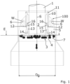
- drilling head 100 The embodiment of a drilling head according to the invention designated as a whole with 100 in the drawing (hereinafter referred to as "drill head 100") is in operation with a Fig. 1 indicated support strand 1, which can be set into rotation about a rotation axis S by means of a rotating device not shown in the drawing.
- the drill head 100 can thus be rotated about the rotation axis S during operation.
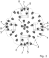
- the drill head has a base body 2 which comprises a front side 4 equipped with a plurality of cutting tools 3.
- the drill head 100 also has extension arms 5, which are arranged offset by 90° in the direction of rotation with respect to their center planes.
- Each extension arm 5 is coupled to the base body 2 by means of a bolt 6, which defines a pivot axis W about which the respective extension arm can pivot.
- the pivot axes W are aligned perpendicular to the axis of rotation S.
- Each extension arm 5 comprises an active side 8 equipped with several cutting tools 7.
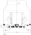
- Each extension arm 5 can be set between Fig. 1 and 2 shown, retracted position, in which each effective side 8 lies with the front side 4 at least almost on a plane E and the drill head has an effective drilling diameter D 0 (see Fig. 1 ), a first disengaged position in which the effective bore diameter D 1 is extended by a first amount B 1 (see Fig. 3 ) and a second disengaged position about the swivel axes W, in which the effective bore diameter D 2 is extended by a second amount B 2 (see Fig. 4 ).
- the active sides 8 of the extension arms 5 extend only in the first, disengaged position ( Fig. 3 ), as well as in the second disengaged position ( Fig. 4 ) relative to the direction of the axis of rotation S at least almost step-free from the front side 4 of the base body 2.
- the active sides 8 each have an angle ⁇ of between 20° and 45°, preferably of approximately 37°, to the front side 4 of the base body 2. In this way, drilling material which has been removed using the cutting tools 7 of the extension arms 5 is directed towards the center of the bore under the effect of gravity and can thus be removed more easily, for example by suction via a suction opening 9 located in the front side 4 of the base body 2.
- a hydraulic cylinder 10 is provided for each extension arm 5.
- Each hydraulic cylinder is articulated at a first end 11 to the base body 2 and at a second end 12 to an actuating lever 13.
- Each actuating lever 13 is articulated with a first end 14 in the region of a side of an extension arm 5 facing the axis of rotation S.
- a second end 15 of the actuating lever 13 is mounted on the base body 2 in a guide 16 so as to be displaceable parallel to the axis of rotation S.
- the actuating levers 13 are designed in such a way that they at least substantially close off the open areas that arise between the front side 4 of the base body 2 and the active sides 8 of the extension arms 5 in the first and second disengaged positions. They thus also serve to form closing elements 17 that prevent drilling material from penetrating into the base body 2 and prevent any possible blocking of the extension arms 5.
Landscapes
- Engineering & Computer Science (AREA)
- Geology (AREA)
- Life Sciences & Earth Sciences (AREA)
- Mining & Mineral Resources (AREA)
- Environmental & Geological Engineering (AREA)
- Fluid Mechanics (AREA)
- Physics & Mathematics (AREA)
- General Life Sciences & Earth Sciences (AREA)
- Geochemistry & Mineralogy (AREA)
- Mechanical Engineering (AREA)
- Earth Drilling (AREA)
- Processing Of Stones Or Stones Resemblance Materials (AREA)
- Drilling And Boring (AREA)
Applications Claiming Priority (4)
| Application Number | Priority Date | Filing Date | Title |
|---|---|---|---|
| DE102018105340.1A DE102018105340A1 (de) | 2018-03-08 | 2018-03-08 | Bohrkopf und diesen umfassendes Bohrsystem |
| PCT/EP2019/055816 WO2019170847A1 (fr) | 2018-03-08 | 2019-03-08 | Tête de forage et système de forage comprenant celle-ci |
| EP22171391.0A EP4056802B1 (fr) | 2018-03-08 | 2019-03-08 | Tête de forage et système de forage incorporè |
| EP19711525.6A EP3762576B1 (fr) | 2018-03-08 | 2019-03-08 | Tête de forage et système de forage incorporè |
Related Parent Applications (2)
| Application Number | Title | Priority Date | Filing Date |
|---|---|---|---|
| EP19711525.6A Division EP3762576B1 (fr) | 2018-03-08 | 2019-03-08 | Tête de forage et système de forage incorporè |
| EP22171391.0A Division EP4056802B1 (fr) | 2018-03-08 | 2019-03-08 | Tête de forage et système de forage incorporè |
Publications (4)
| Publication Number | Publication Date |
|---|---|
| EP4497908A2 true EP4497908A2 (fr) | 2025-01-29 |
| EP4497908A3 EP4497908A3 (fr) | 2025-04-02 |
| EP4497908C0 EP4497908C0 (fr) | 2025-12-10 |
| EP4497908B1 EP4497908B1 (fr) | 2025-12-10 |
Family
ID=65812273
Family Applications (3)
| Application Number | Title | Priority Date | Filing Date |
|---|---|---|---|
| EP22171391.0A Active EP4056802B1 (fr) | 2018-03-08 | 2019-03-08 | Tête de forage et système de forage incorporè |
| EP24219519.6A Active EP4497908B1 (fr) | 2018-03-08 | 2019-03-08 | Tête de forage et système de forage incorporè |
| EP19711525.6A Active EP3762576B1 (fr) | 2018-03-08 | 2019-03-08 | Tête de forage et système de forage incorporè |
Family Applications Before (1)
| Application Number | Title | Priority Date | Filing Date |
|---|---|---|---|
| EP22171391.0A Active EP4056802B1 (fr) | 2018-03-08 | 2019-03-08 | Tête de forage et système de forage incorporè |
Family Applications After (1)
| Application Number | Title | Priority Date | Filing Date |
|---|---|---|---|
| EP19711525.6A Active EP3762576B1 (fr) | 2018-03-08 | 2019-03-08 | Tête de forage et système de forage incorporè |
Country Status (5)
| Country | Link |
|---|---|
| EP (3) | EP4056802B1 (fr) |
| JP (3) | JP7346432B2 (fr) |
| CN (3) | CN111819337B (fr) |
| DE (1) | DE102018105340A1 (fr) |
| WO (1) | WO2019170847A1 (fr) |
Families Citing this family (3)
| Publication number | Priority date | Publication date | Assignee | Title |
|---|---|---|---|---|
| CN112252974A (zh) * | 2020-10-15 | 2021-01-22 | 西安乔木科技技术有限公司 | 一种长距离定向钻的可变径扩孔钻头及其施工方法 |
| CN114396289A (zh) * | 2021-11-12 | 2022-04-26 | 四川杰皓方机械设备有限公司 | 方桩圆钻头定位器 |
| CN120701248B (zh) * | 2025-08-27 | 2025-11-14 | 西安卓力科技发展有限公司 | 阶梯式扩孔机构及履带式扩孔吊运一体装置 |
Citations (1)
| Publication number | Priority date | Publication date | Assignee | Title |
|---|---|---|---|---|
| KR20060006754A (ko) | 2005-12-31 | 2006-01-19 | 주식회사 동아지질 | 절첩식 선단확대 굴착비트 |
Family Cites Families (26)
| Publication number | Priority date | Publication date | Assignee | Title |
|---|---|---|---|---|
| US2734733A (en) * | 1956-02-14 | wilms | ||
| JPS4817003B1 (fr) * | 1969-10-30 | 1973-05-26 | ||
| JPS5245043Y2 (fr) * | 1974-08-20 | 1977-10-13 | ||
| US4461361A (en) * | 1981-12-07 | 1984-07-24 | Dresser Industries, Inc. | Underreamer with cylindrical boss and socket hinge assembly for the cutter arm |
| GB9007023D0 (en) * | 1990-03-29 | 1990-05-30 | Smith Int North Sea | Junk mill |
| US5141063A (en) * | 1990-08-08 | 1992-08-25 | Quesenbury Jimmy B | Restriction enhancement drill |
| DE4211048C1 (fr) * | 1992-04-02 | 1993-05-06 | Boart Hwf Gmbh & Co Kg Hartmetallwerkzeugfabrik, 6419 Burghaun, De | |
| JP3497948B2 (ja) * | 1996-06-17 | 2004-02-16 | 日立建機株式会社 | 拡底孔施工用の掘削装置及び拡底孔施工方法 |
| JPH10231677A (ja) * | 1997-02-18 | 1998-09-02 | Mitsubishi Materials Corp | 掘削工具 |
| JP2971048B2 (ja) * | 1997-07-03 | 1999-11-02 | 日本ベース株式会社 | 拡径孔掘削装置 |
| JP3864645B2 (ja) * | 1999-11-22 | 2007-01-10 | 三菱マテリアル株式会社 | 掘削工具 |
| CA2401917A1 (fr) * | 2002-09-06 | 2004-03-06 | Tesco Corporation | Trepan extensible |
| JP4501407B2 (ja) * | 2002-11-20 | 2010-07-14 | 三菱マテリアル株式会社 | 掘削工具 |
| US6953096B2 (en) * | 2002-12-31 | 2005-10-11 | Weatherford/Lamb, Inc. | Expandable bit with secondary release device |
| US7383900B2 (en) * | 2003-05-21 | 2008-06-10 | Shell Oil Company | Drill bit and system for drilling a borehole |
| JP2006283516A (ja) | 2005-04-05 | 2006-10-19 | Mitsubishi Materials Corp | 掘削工具及び掘削工法 |
| US7753139B2 (en) * | 2005-07-06 | 2010-07-13 | Smith International, Inc. | Cutting device with multiple cutting structures |
| ATE438783T1 (de) * | 2005-10-18 | 2009-08-15 | Prad Res & Dev Nv | Expandierbares bohrwerkzeug |
| US7506703B2 (en) * | 2006-01-18 | 2009-03-24 | Smith International, Inc. | Drilling and hole enlargement device |
| US8028767B2 (en) * | 2006-12-04 | 2011-10-04 | Baker Hughes, Incorporated | Expandable stabilizer with roller reamer elements |
| KR20140033852A (ko) * | 2012-09-11 | 2014-03-19 | 엄광수 | 지반 굴착용 리머드릴 |
| GB2522062A (en) * | 2014-01-14 | 2015-07-15 | Fugro Seacore Ltd | Drill Bit Assembly |
| CN105625947B (zh) * | 2016-03-24 | 2018-12-25 | 平煤建工集团特殊凿井工程有限公司 | 一种用于钻凿可变孔径桩孔的钻头 |
| JP2018044285A (ja) * | 2016-09-12 | 2018-03-22 | 三菱マテリアル株式会社 | 掘削工具 |
| CN112252974A (zh) * | 2020-10-15 | 2021-01-22 | 西安乔木科技技术有限公司 | 一种长距离定向钻的可变径扩孔钻头及其施工方法 |
| CN120701248B (zh) * | 2025-08-27 | 2025-11-14 | 西安卓力科技发展有限公司 | 阶梯式扩孔机构及履带式扩孔吊运一体装置 |
-
2018
- 2018-03-08 DE DE102018105340.1A patent/DE102018105340A1/de not_active Ceased
-
2019
- 2019-03-08 CN CN201980017618.XA patent/CN111819337B/zh active Active
- 2019-03-08 EP EP22171391.0A patent/EP4056802B1/fr active Active
- 2019-03-08 JP JP2020546993A patent/JP7346432B2/ja active Active
- 2019-03-08 EP EP24219519.6A patent/EP4497908B1/fr active Active
- 2019-03-08 CN CN202310369679.0A patent/CN116498215A/zh active Pending
- 2019-03-08 WO PCT/EP2019/055816 patent/WO2019170847A1/fr not_active Ceased
- 2019-03-08 EP EP19711525.6A patent/EP3762576B1/fr active Active
- 2019-03-08 CN CN202310369676.7A patent/CN116498214A/zh active Pending
-
2023
- 2023-09-05 JP JP2023143788A patent/JP7608545B2/ja active Active
-
2024
- 2024-12-18 JP JP2024221979A patent/JP2025038154A/ja active Pending
Patent Citations (1)
| Publication number | Priority date | Publication date | Assignee | Title |
|---|---|---|---|---|
| KR20060006754A (ko) | 2005-12-31 | 2006-01-19 | 주식회사 동아지질 | 절첩식 선단확대 굴착비트 |
Also Published As
| Publication number | Publication date |
|---|---|
| EP3762576B1 (fr) | 2022-05-04 |
| EP4497908C0 (fr) | 2025-12-10 |
| JP2025038154A (ja) | 2025-03-18 |
| JP2021515128A (ja) | 2021-06-17 |
| WO2019170847A1 (fr) | 2019-09-12 |
| EP3762576A1 (fr) | 2021-01-13 |
| EP4497908A3 (fr) | 2025-04-02 |
| EP4056802B1 (fr) | 2025-01-01 |
| JP2023164942A (ja) | 2023-11-14 |
| EP4497908B1 (fr) | 2025-12-10 |
| JP7608545B2 (ja) | 2025-01-06 |
| CN116498215A (zh) | 2023-07-28 |
| CN111819337A (zh) | 2020-10-23 |
| DE102018105340A1 (de) | 2019-09-12 |
| JP7346432B2 (ja) | 2023-09-19 |
| EP4056802C0 (fr) | 2025-01-01 |
| EP4056802A1 (fr) | 2022-09-14 |
| CN111819337B (zh) | 2023-04-04 |
| CN116498214A (zh) | 2023-07-28 |
Similar Documents
| Publication | Publication Date | Title |
|---|---|---|
| DE69605779T2 (de) | Von der öberfläche aus kontrolliertes richtbohrwerkzeug | |
| EP4056802B1 (fr) | Tête de forage et système de forage incorporè | |
| DE112008001519T5 (de) | Bohrmeißel | |
| EP2562348B1 (fr) | Agencement de forage sous-marin et procédé d'exécution d'un forage | |
| DE102004056545A1 (de) | Vorrichtung und Verfahren zum Gewinnen von Informationen aus einer unterirdischen Formation | |
| EP2770156B1 (fr) | Outil de forage et procédé de forage terrestre | |
| WO2015131984A1 (fr) | Dispositif de forage servant à réaliser un trou de forage et système de positionnement du dispositif de forage | |
| EP0065284B1 (fr) | Alésoir | |
| DE202018006056U1 (de) | Schneckenbohrer zur Herstellung von Bohrpfählen | |
| DE3245992A1 (de) | Vorrichtung an kombiniertem baggerloeffel und frostaufreisser | |
| DE2932062A1 (de) | Grubenbohrerausleger | |
| AT363044B (de) | Vorrichtung zum niederbringen einer verrohrten tiefbohrung zur herstellung einer verrohrten pfahlgruendung | |
| EP2927417A2 (fr) | Couronne de foreuse rotative à percussion ouvrant, en particulier pour le forage de morts-terrains | |
| DE2413418C3 (de) | Verfahren zur Herstellung von Pfahlgrundungen sowie Fertigbetonpfahl zur Verwendung bei diesem Verfahren | |
| DE4211059C1 (fr) | ||
| AT395340B (de) | Drehbohrvorrichtung zum erweitern von vertikalen bohrungen | |
| EP1167635A1 (fr) | Dispositif pour insérer une conduite | |
| DE602004003418T2 (de) | Gewindeschneideeinrichtung | |
| DE3423789A1 (de) | Bohreinrichtung fuer gesteinbohrungen | |
| DE3601713A1 (de) | Fahrbare bohr- und rammanlage | |
| EP4198253B1 (fr) | Outil de forage et procédé de production d'un forage dans le sol | |
| EP3792407A1 (fr) | Dispositif de pose pour la pose de matériaux en brins flexibles dans le sol et dispositif d'insertion principale pour un tel dispositif de pose | |
| DE102020131532A1 (de) | Bohrvorrichtung | |
| DE2236111C3 (de) | Werkzeug zum Bohren und Aufwelten eines Bohrloches | |
| DE202026100322U1 (de) | Bohrspitzenstruktur für weichen Bahnkörpergrund |
Legal Events
| Date | Code | Title | Description |
|---|---|---|---|
| PUAI | Public reference made under article 153(3) epc to a published international application that has entered the european phase |
Free format text: ORIGINAL CODE: 0009012 |
|
| STAA | Information on the status of an ep patent application or granted ep patent |
Free format text: STATUS: THE APPLICATION HAS BEEN PUBLISHED |
|
| AC | Divisional application: reference to earlier application |
Ref document number: 3762576 Country of ref document: EP Kind code of ref document: P Ref document number: 4056802 Country of ref document: EP Kind code of ref document: P |
|
| AK | Designated contracting states |
Kind code of ref document: A2 Designated state(s): AL AT BE BG CH CY CZ DE DK EE ES FI FR GB GR HR HU IE IS IT LI LT LU LV MC MK MT NL NO PL PT RO RS SE SI SK SM TR |
|
| PUAL | Search report despatched |
Free format text: ORIGINAL CODE: 0009013 |
|
| AK | Designated contracting states |
Kind code of ref document: A3 Designated state(s): AL AT BE BG CH CY CZ DE DK EE ES FI FR GB GR HR HU IE IS IT LI LT LU LV MC MK MT NL NO PL PT RO RS SE SI SK SM TR |
|
| RIC1 | Information provided on ipc code assigned before grant |
Ipc: E21B 7/28 20060101ALI20250227BHEP Ipc: E21B 10/32 20060101AFI20250227BHEP |
|
| STAA | Information on the status of an ep patent application or granted ep patent |
Free format text: STATUS: REQUEST FOR EXAMINATION WAS MADE |
|
| 17P | Request for examination filed |
Effective date: 20250603 |
|
| GRAP | Despatch of communication of intention to grant a patent |
Free format text: ORIGINAL CODE: EPIDOSNIGR1 |
|
| STAA | Information on the status of an ep patent application or granted ep patent |
Free format text: STATUS: GRANT OF PATENT IS INTENDED |
|
| INTG | Intention to grant announced |
Effective date: 20250904 |
|
| GRAS | Grant fee paid |
Free format text: ORIGINAL CODE: EPIDOSNIGR3 |
|
| GRAA | (expected) grant |
Free format text: ORIGINAL CODE: 0009210 |
|
| STAA | Information on the status of an ep patent application or granted ep patent |
Free format text: STATUS: THE PATENT HAS BEEN GRANTED |
|
| AC | Divisional application: reference to earlier application |
Ref document number: 4056802 Country of ref document: EP Kind code of ref document: P Ref document number: 3762576 Country of ref document: EP Kind code of ref document: P |
|
| AK | Designated contracting states |
Kind code of ref document: B1 Designated state(s): AL AT BE BG CH CY CZ DE DK EE ES FI FR GB GR HR HU IE IS IT LI LT LU LV MC MK MT NL NO PL PT RO RS SE SI SK SM TR |
|
| REG | Reference to a national code |
Ref country code: CH Ref legal event code: F10 Free format text: ST27 STATUS EVENT CODE: U-0-0-F10-F00 (AS PROVIDED BY THE NATIONAL OFFICE) Effective date: 20251210 Ref country code: GB Ref legal event code: FG4D Free format text: NOT ENGLISH |
|
| REG | Reference to a national code |
Ref country code: DE Ref legal event code: R096 Ref document number: 502019014186 Country of ref document: DE |
|
| REG | Reference to a national code |
Ref country code: IE Ref legal event code: FG4D Free format text: LANGUAGE OF EP DOCUMENT: GERMAN |
|
| U01 | Request for unitary effect filed |
Effective date: 20260107 |
|
| U07 | Unitary effect registered |
Designated state(s): AT BE BG DE DK EE FI FR IT LT LU LV MT NL PT RO SE SI Effective date: 20260114 |
|
| U20 | Renewal fee for the european patent with unitary effect paid |
Year of fee payment: 8 Effective date: 20260129 |
|
| PGFP | Annual fee paid to national office [announced via postgrant information from national office to epo] |
Ref country code: GB Payment date: 20260128 Year of fee payment: 8 |
|
| PG25 | Lapsed in a contracting state [announced via postgrant information from national office to epo] |
Ref country code: ES Free format text: LAPSE BECAUSE OF FAILURE TO SUBMIT A TRANSLATION OF THE DESCRIPTION OR TO PAY THE FEE WITHIN THE PRESCRIBED TIME-LIMIT Effective date: 20251210 |
|
| PG25 | Lapsed in a contracting state [announced via postgrant information from national office to epo] |
Ref country code: NO Free format text: LAPSE BECAUSE OF FAILURE TO SUBMIT A TRANSLATION OF THE DESCRIPTION OR TO PAY THE FEE WITHIN THE PRESCRIBED TIME-LIMIT Effective date: 20260310 |
|
| PG25 | Lapsed in a contracting state [announced via postgrant information from national office to epo] |
Ref country code: HR Free format text: LAPSE BECAUSE OF FAILURE TO SUBMIT A TRANSLATION OF THE DESCRIPTION OR TO PAY THE FEE WITHIN THE PRESCRIBED TIME-LIMIT Effective date: 20251210 |
|
| PG25 | Lapsed in a contracting state [announced via postgrant information from national office to epo] |
Ref country code: RS Free format text: LAPSE BECAUSE OF FAILURE TO SUBMIT A TRANSLATION OF THE DESCRIPTION OR TO PAY THE FEE WITHIN THE PRESCRIBED TIME-LIMIT Effective date: 20260310 |