EP4497975A1 - Architecture de transmission améliorée pour véhicules agricoles - Google Patents
Architecture de transmission améliorée pour véhicules agricoles Download PDFInfo
- Publication number
- EP4497975A1 EP4497975A1 EP24189645.5A EP24189645A EP4497975A1 EP 4497975 A1 EP4497975 A1 EP 4497975A1 EP 24189645 A EP24189645 A EP 24189645A EP 4497975 A1 EP4497975 A1 EP 4497975A1
- Authority
- EP
- European Patent Office
- Prior art keywords
- shaft
- stage
- gear ratio
- carried
- gear
- Prior art date
- Legal status (The legal status is an assumption and is not a legal conclusion. Google has not performed a legal analysis and makes no representation as to the accuracy of the status listed.)
- Pending
Links
Images



Classifications
-
- F—MECHANICAL ENGINEERING; LIGHTING; HEATING; WEAPONS; BLASTING
- F16—ENGINEERING ELEMENTS AND UNITS; GENERAL MEASURES FOR PRODUCING AND MAINTAINING EFFECTIVE FUNCTIONING OF MACHINES OR INSTALLATIONS; THERMAL INSULATION IN GENERAL
- F16H—GEARING
- F16H3/00—Toothed gearings for conveying rotary motion with variable gear ratio or for reversing rotary motion
- F16H3/006—Toothed gearings for conveying rotary motion with variable gear ratio or for reversing rotary motion power being selectively transmitted by parallel flow paths, e.g. dual clutch transmissions
-
- F—MECHANICAL ENGINEERING; LIGHTING; HEATING; WEAPONS; BLASTING
- F16—ENGINEERING ELEMENTS AND UNITS; GENERAL MEASURES FOR PRODUCING AND MAINTAINING EFFECTIVE FUNCTIONING OF MACHINES OR INSTALLATIONS; THERMAL INSULATION IN GENERAL
- F16H—GEARING
- F16H3/00—Toothed gearings for conveying rotary motion with variable gear ratio or for reversing rotary motion
- F16H3/02—Toothed gearings for conveying rotary motion with variable gear ratio or for reversing rotary motion without gears having orbital motion
- F16H3/08—Toothed gearings for conveying rotary motion with variable gear ratio or for reversing rotary motion without gears having orbital motion exclusively or essentially with continuously meshing gears, that can be disengaged from their shafts
- F16H3/087—Toothed gearings for conveying rotary motion with variable gear ratio or for reversing rotary motion without gears having orbital motion exclusively or essentially with continuously meshing gears, that can be disengaged from their shafts characterised by the disposition of the gears
- F16H3/093—Toothed gearings for conveying rotary motion with variable gear ratio or for reversing rotary motion without gears having orbital motion exclusively or essentially with continuously meshing gears, that can be disengaged from their shafts characterised by the disposition of the gears with two or more countershafts
-
- F—MECHANICAL ENGINEERING; LIGHTING; HEATING; WEAPONS; BLASTING
- F16—ENGINEERING ELEMENTS AND UNITS; GENERAL MEASURES FOR PRODUCING AND MAINTAINING EFFECTIVE FUNCTIONING OF MACHINES OR INSTALLATIONS; THERMAL INSULATION IN GENERAL
- F16H—GEARING
- F16H3/00—Toothed gearings for conveying rotary motion with variable gear ratio or for reversing rotary motion
- F16H3/02—Toothed gearings for conveying rotary motion with variable gear ratio or for reversing rotary motion without gears having orbital motion
- F16H3/08—Toothed gearings for conveying rotary motion with variable gear ratio or for reversing rotary motion without gears having orbital motion exclusively or essentially with continuously meshing gears, that can be disengaged from their shafts
- F16H3/087—Toothed gearings for conveying rotary motion with variable gear ratio or for reversing rotary motion without gears having orbital motion exclusively or essentially with continuously meshing gears, that can be disengaged from their shafts characterised by the disposition of the gears
- F16H3/093—Toothed gearings for conveying rotary motion with variable gear ratio or for reversing rotary motion without gears having orbital motion exclusively or essentially with continuously meshing gears, that can be disengaged from their shafts characterised by the disposition of the gears with two or more countershafts
- F16H3/097—Toothed gearings for conveying rotary motion with variable gear ratio or for reversing rotary motion without gears having orbital motion exclusively or essentially with continuously meshing gears, that can be disengaged from their shafts characterised by the disposition of the gears with two or more countershafts the input and output shafts being aligned on the same axis
-
- F—MECHANICAL ENGINEERING; LIGHTING; HEATING; WEAPONS; BLASTING
- F16—ENGINEERING ELEMENTS AND UNITS; GENERAL MEASURES FOR PRODUCING AND MAINTAINING EFFECTIVE FUNCTIONING OF MACHINES OR INSTALLATIONS; THERMAL INSULATION IN GENERAL
- F16H—GEARING
- F16H3/00—Toothed gearings for conveying rotary motion with variable gear ratio or for reversing rotary motion
- F16H3/02—Toothed gearings for conveying rotary motion with variable gear ratio or for reversing rotary motion without gears having orbital motion
- F16H3/08—Toothed gearings for conveying rotary motion with variable gear ratio or for reversing rotary motion without gears having orbital motion exclusively or essentially with continuously meshing gears, that can be disengaged from their shafts
- F16H3/087—Toothed gearings for conveying rotary motion with variable gear ratio or for reversing rotary motion without gears having orbital motion exclusively or essentially with continuously meshing gears, that can be disengaged from their shafts characterised by the disposition of the gears
- F16H3/093—Toothed gearings for conveying rotary motion with variable gear ratio or for reversing rotary motion without gears having orbital motion exclusively or essentially with continuously meshing gears, that can be disengaged from their shafts characterised by the disposition of the gears with two or more countershafts
- F16H2003/0933—Toothed gearings for conveying rotary motion with variable gear ratio or for reversing rotary motion without gears having orbital motion exclusively or essentially with continuously meshing gears, that can be disengaged from their shafts characterised by the disposition of the gears with two or more countershafts with coaxial countershafts
Definitions
- the present invention relates to a transmission architecture, in particular a transmission architecture for an off-road vehicle such as an agricultural vehicle and to a related method for controlling the gear shifting of such transmission.
- Transmissions for off-road vehicles such as agricultural vehicles offer different configuration, for instance:
- DCT dual-clutch transmission
- DCT architecture has been applied in the field of the transmissions for agricultural vehicles.
- An example of such DCT architecture is disclosed in patent document IT102022000024729 A1 .
- Aim of the present invention is to satisfy the above-mentioned needs in a cost-effective and optimized way.
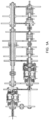
- Figures 1 and 2 disclose a transmission 1 for an off-road vehicle, such as an agricultural vehicle, e.g. a tractor (not illustrated), comprising an engine input shaft 2, operatively connected to a torque source E, such as an internal combustion engine of the work vehicle, and an output shaft 3, which can be coupled to a drive axle of the off-road vehicle.
- a torque source E such as an internal combustion engine of the work vehicle
- an output shaft 3 which can be coupled to a drive axle of the off-road vehicle.
- the transmission 1 essentially comprises, operatively connected in series one to the other between input shaft 2 and output shaft 3, an input stage A, a gear ratio stage B, and a range gear ratio stage C.
- the input stage A may be realized in different manner in order to vary rotational direction of input shaft 2 towards gear ratio B, i.e. between a forward motion and a rearward motion.
- the input stage A comprises a first and a second gearings 4, 5 selectively connectable to a first support shaft 6.
- the first gearing 4 comprises a first wheel 4' rotatably carried by input shaft 2 and a second wheel 4" carried in a fixed manner by the first support shaft 6 while the second gearing comprises a first wheel 5' rotatably carried by input shaft 2 and a second wheel 5" carried in a fixed manner by the first support shaft 6 and a third wheel 5"' operatively interposed between the first and the second wheels 5', 5" .
- the first wheels 4', 5' of gearings 4, 5 are selectively fixed to the input shaft 2 via coupling means 7 such as clutch means or equivalent ones.
- the first support shaft 6 provides input torque to the gear ratio stage B.
- this latter comprises a coupling stage B' and an even-odd stage B''.
- coupling stage B' is configured to allow a jump powershift connection or a semi powershift connection between the fourth and the fifth gear ratio defined in even-odd stages B" as described further below in detail.
- the even-odd stage B" comprises a pair of shafts, namely an odd shaft 11, an even shaft 12 that are coupled via coupling stage B' to the input stage A and a plurality of gears 21, 22 accommodated on respectively even or odd shafts 11, 12 and having a different size one with respect to the other.
- the even shaft 11 may carry four gears 21, namely a first gear 21 I having the biggest diameter, a fourth gear 21 IV having the smallest diameter and a second and third gears 21 II , 21 III having respective diameters comprised between the ones of first and the fourth gears 21 I , 21 IV .
- the odd shaft 12 may carry four gears 22, namely a first gear 22 I having the biggest diameter, a fourth gear 22 IV having the smallest diameter and a second and third gears 22 II , 22 III having respective diameters comprised between the ones of first and the fourth gears 22 I , 22 IV .
- gears 21 and 22 have the same diameter of the gear 21, 22 with which each meshes.
- the gears of gears sets 21, 22, when selected, represent the different speed ratios of the transmission, namely a first, a second, a third, a fourth, a fifth, a sixth and a seventh speed ratio according to the specific selection of one of the aforementioned wheels 21, 22.
- wheels 22 are supported in a rotatable free manner the respective even shaft 12, e.g. by means of bearings, so that they are not forced to rotate to the same speed of the respective even shaft 12.
- they are fixedly engaged to the even shaft 12 by coupling means 23 such as dog clutches.
- even shaft 12 may comprise two dog clutches 17 interposed respectively between the gear 15 I - 15 III and 15 II -1 IV .
- At least one gear 21 I , 21 III is carried fixedly by odd shaft 11 while the remaining ones 21 II , 21 IV are carried by an auxiliary shaft 24 that is carried in a rotatably free manner over odd shaft 11.
- the second and fourth wheels 21 II , 21 IV are carried rigidly by the auxiliary shaft 24 while the first and third wheels 21 I , 21 III are carried rigidly by odd shaft 11.
- auxiliary shaft 24 is selectively connectable to the odd shaft 11 via coupling means 23 such as the one above described.
- the auxiliary shaft 24 is connected to the coupling stage B' that comprises a first gearing 25 comprising a first wheel 25' fixedly carried by auxiliary shaft 24 and a second wheel 25" that is rotatably free carried by even shaft 12.
- the coupling stage B' further comprises a first clutch means 27 configured to connect together the second wheel 25'' to the intermediate shaft 6.
- the coupling stage B' comprises a second gearing 29 comprising a first wheel 29' fixedly carried by odd shaft 11 and a second wheel 29'' rotatably carried by intermediate shaft 6.
- the coupling stage B' comprising second clutch means 28 configured to be selectively fix to the second wheel 29'' to the intermediate shaft 6.
- the first and second clutch means 27, 28 are preferably rotationally engaged together via their respective housings.
- the coupling stage B' further comprises third clutch means 40 configured to selectively couple together the intermediate shaft 6 directly to even shaft 12.
- the range gear stage C adds a plurality of additional gear ratio that are combined with the gear ratios defined by the gear ratio stage B. In the disclosed embodiment, three range gear ratio are provided.
- the range gear ratio stage C then comprises a first, a second and a third range gearings 31, 32, 33 each comprising a first wheel 31', 32', 33' and a second wheel 31", 32", 33".
- first gearing is the so-called fast direct range
- second gearing is the so-called medium range
- third gearing is the so-called low range.
- the first wheels 32', 33' of the second and third range gearings 32', 33' are rotatably free carried by odd shaft 11, in particular fixed to an auxiliary shaft 34 that is rotatably free carried by odd shaft 11, while second wheels 32'', 33'' of the second and third range gearing 32, 33 are rotatably free carried by the output shaft 3.
- the first wheel 31' of the first range gearing 31 is fixedly carried by the auxiliary shaft 34 while the second wheel 31" is fixedly carried by even shaft 12.
- the second wheels 32'', 33' of the second and third range gears are selectively connected to output shaft 3 via coupling means 23 of the above described typology, while the second wheel 31'' of the first range gear 31 may be directly connected to output shaft 3, i.e. making the output shaft 3 directly connected to even shaft 12.
- the above described clutches 7, 27, 28, 30 and coupling means 23 can be selected by respective actuators (not shown) that are controlled by an electronic control unit (not shown).
- the electronic control unit controls said clutches or said control means by sending control electric signals directed to the respective clutches or coupling means to be controlled.
- the electronic control unit can be either the ECU of the vehicle or driveline ECU of the vehicle.
- the electronic control unit is configured to control the above cited elements of the transmission 1 as per direct input command of the user of the vehicle or in automatic way following the shift control logic deployed into a specific software code, which can be memorized into the electronic unit.
- the vehicle may be provided by a dedicated control software code in the ECU of the transmission configured to recognize signals from sensors installed on the vehicle, e.g. the torque demand at the output shaft 3 and the speed of the engine input shaft 2, and automatically define the gearshift without any user intervention.
- the vehicle is driving, e.g. forward, in I gear ratio, i.e. in the configuration shown in figure 1A .
- the torque passes therefore from input module A from input shaft 2 toward first support shaft 6. If reverse motion is needed, input stage A is controlled accordingly.
- the transmission may lead to twenty-seven overall speed ratio.
- Figure 2 discloses a second embodiment of transmission 1 that differs from the first embodiment of figure 1 in the coupling stage B' and in the range gear stage C.
- the coupling stage B' does not comprise clutch means 30, therefore there is no possibility of adding a jump ratio by directly connecting the intermediate shaft 6 and the even shaft 12.
- the range gear stage C does not comprise the medium range wheel thereby defining only two possible range gear ratios.
- the vehicle is driving, e.g. forward, in I gear ratio, i.e. in the configuration shown in figure 2A .
- the torque passes therefore from input module A from input shaft 2 toward first support shaft 6. If reverse motion is needed, input stage A is controlled accordingly.
- the transmission may lead to sixteen overall speed ratio.
- the invention also relates to a method for operating a transmission 1 as described above for shifting from a gear ratio of the gear ratio stage B to a requested gear ratio of the gear ratio stage B and comprising the following steps:
- the proposed arrangement allows to reduce the inertia at gear switching, thereby smoothing the gear switching. Furthermore, reduction of inertia allows to reduce the weight and the cost of manufacturing gears and shafts.
- the proposed transmission uses less clutches thereby reducing their power consumption therefore increasing the efficiency of the transmission architecture.
- gears of gear ratio, range and idler gears may be varied according to vehicle necessity.
- transmission may comprise different elements with respect to the described one, e.g. the number and/or typologies of clutches, gears and dog clutches may be varied. Accordingly, input stage A may be realized in any convenient manner.
- control and typology of coupling means 30 may be implemented with any typology of control, e.g. a hydraulic, electric or pneumatic in alternative or in combinations.
Landscapes
- Engineering & Computer Science (AREA)
- General Engineering & Computer Science (AREA)
- Mechanical Engineering (AREA)
- Structure Of Transmissions (AREA)
Applications Claiming Priority (1)
| Application Number | Priority Date | Filing Date | Title |
|---|---|---|---|
| IT102023000015483A IT202300015483A1 (it) | 2023-07-24 | 2023-07-24 | Architettura di trasmissione migliorata per veicoli agricoli |
Publications (1)
| Publication Number | Publication Date |
|---|---|
| EP4497975A1 true EP4497975A1 (fr) | 2025-01-29 |
Family
ID=88207263
Family Applications (1)
| Application Number | Title | Priority Date | Filing Date |
|---|---|---|---|
| EP24189645.5A Pending EP4497975A1 (fr) | 2023-07-24 | 2024-07-19 | Architecture de transmission améliorée pour véhicules agricoles |
Country Status (2)
| Country | Link |
|---|---|
| EP (1) | EP4497975A1 (fr) |
| IT (1) | IT202300015483A1 (fr) |
Citations (4)
| Publication number | Priority date | Publication date | Assignee | Title |
|---|---|---|---|---|
| US4294130A (en) * | 1977-04-27 | 1981-10-13 | Kubota Ltd. | Transmission for tractor |
| EP0128251A1 (fr) * | 1983-06-08 | 1984-12-19 | Deere & Company | Boîte de vitesse à rapports multiples |
| US5901606A (en) * | 1996-06-18 | 1999-05-11 | Kubota Corporation | Transmission for a tractor |
| IT202200024729A1 (it) | 2022-11-30 | 2024-05-30 | Cnh Ind Italia Spa | Architettura di trasmissione migliorata per veicoli agricoli |
-
2023
- 2023-07-24 IT IT102023000015483A patent/IT202300015483A1/it unknown
-
2024
- 2024-07-19 EP EP24189645.5A patent/EP4497975A1/fr active Pending
Patent Citations (4)
| Publication number | Priority date | Publication date | Assignee | Title |
|---|---|---|---|---|
| US4294130A (en) * | 1977-04-27 | 1981-10-13 | Kubota Ltd. | Transmission for tractor |
| EP0128251A1 (fr) * | 1983-06-08 | 1984-12-19 | Deere & Company | Boîte de vitesse à rapports multiples |
| US5901606A (en) * | 1996-06-18 | 1999-05-11 | Kubota Corporation | Transmission for a tractor |
| IT202200024729A1 (it) | 2022-11-30 | 2024-05-30 | Cnh Ind Italia Spa | Architettura di trasmissione migliorata per veicoli agricoli |
Also Published As
| Publication number | Publication date |
|---|---|
| IT202300015483A1 (it) | 2025-01-24 |
Similar Documents
| Publication | Publication Date | Title |
|---|---|---|
| US7360466B2 (en) | Double clutch transmission | |
| US7621195B2 (en) | Vehicle transmission | |
| EP3911873B1 (fr) | Architecture hybride électrique de transmission à double embrayage pour véhicules agricoles | |
| US7958798B2 (en) | Speed change system for working vehicle | |
| EP2510259B1 (fr) | Transmission commandée en charge pour un véhicule à moteur | |
| EP2256369B1 (fr) | Transmission a double embrayage pour vehicule | |
| EP2126411B2 (fr) | Transmission de vehicule a double embrayage a rapports multiples | |
| US6826974B2 (en) | Automatic transmission | |
| EP1961994A2 (fr) | Système de transmission pour véhicule de chantier | |
| US20100162840A1 (en) | Double clutch gear change transmission | |
| US4858495A (en) | Multi-speed powershift transmission | |
| US7278950B2 (en) | Stage-geared gearbox for motor vehicles | |
| US6647817B2 (en) | Automatic transmission | |
| EP4497974A1 (fr) | Architecture de transmission améliorée pour véhicules agricoles | |
| EP4497969A2 (fr) | Architecture de transmission améliorée pour véhicules agricoles | |
| EP4497970A1 (fr) | Architecture de transmission améliorée pour véhicules agricoles | |
| EP4585828A1 (fr) | Architecture de transmission améliorée pour véhicules agricoles | |
| EP4497976A1 (fr) | Architecture de transmission améliorée pour véhicules agricoles | |
| WO2010071247A1 (fr) | Transmission à embrayages multiples, mct | |
| EP4411174A1 (fr) | Transmission à double embrayage pour véhicules agricoles | |
| EP4411172A1 (fr) | Transmission à double embrayage pour véhicules agricoles | |
| EP4411173A1 (fr) | Transmission à double embrayage pour véhicules agricoles | |
| JPS61274147A (ja) | 歯車式変速装置 | |
| EP4411171A1 (fr) | Transmission à double embrayage pour véhicules agricoles | |
| US20250215963A1 (en) | Dual clutch transmission architecture for agricultural vehicles |
Legal Events
| Date | Code | Title | Description |
|---|---|---|---|
| PUAI | Public reference made under article 153(3) epc to a published international application that has entered the european phase |
Free format text: ORIGINAL CODE: 0009012 |
|
| STAA | Information on the status of an ep patent application or granted ep patent |
Free format text: STATUS: THE APPLICATION HAS BEEN PUBLISHED |
|
| AK | Designated contracting states |
Kind code of ref document: A1 Designated state(s): AL AT BE BG CH CY CZ DE DK EE ES FI FR GB GR HR HU IE IS IT LI LT LU LV MC ME MK MT NL NO PL PT RO RS SE SI SK SM TR |
|
| STAA | Information on the status of an ep patent application or granted ep patent |
Free format text: STATUS: REQUEST FOR EXAMINATION WAS MADE |
|
| 17P | Request for examination filed |
Effective date: 20250729 |
|
| GRAP | Despatch of communication of intention to grant a patent |
Free format text: ORIGINAL CODE: EPIDOSNIGR1 |
|
| STAA | Information on the status of an ep patent application or granted ep patent |
Free format text: STATUS: GRANT OF PATENT IS INTENDED |
|
| INTG | Intention to grant announced |
Effective date: 20260325 |