EP4497989A1 - Raccord de carburant, système de ravitaillement, système de contrôle et procédure de ravitaillement - Google Patents
Raccord de carburant, système de ravitaillement, système de contrôle et procédure de ravitaillement Download PDFInfo
- Publication number
- EP4497989A1 EP4497989A1 EP23187758.0A EP23187758A EP4497989A1 EP 4497989 A1 EP4497989 A1 EP 4497989A1 EP 23187758 A EP23187758 A EP 23187758A EP 4497989 A1 EP4497989 A1 EP 4497989A1
- Authority
- EP
- European Patent Office
- Prior art keywords
- refueling
- tank
- control unit
- coupling
- filler neck
- Prior art date
- Legal status (The legal status is an assumption and is not a legal conclusion. Google has not performed a legal analysis and makes no representation as to the accuracy of the status listed.)
- Withdrawn
Links
Images








Classifications
-
- F—MECHANICAL ENGINEERING; LIGHTING; HEATING; WEAPONS; BLASTING
- F17—STORING OR DISTRIBUTING GASES OR LIQUIDS
- F17C—VESSELS FOR CONTAINING OR STORING COMPRESSED, LIQUEFIED OR SOLIDIFIED GASES; FIXED-CAPACITY GAS-HOLDERS; FILLING VESSELS WITH, OR DISCHARGING FROM VESSELS, COMPRESSED, LIQUEFIED, OR SOLIDIFIED GASES
- F17C5/00—Methods or apparatus for filling containers with liquefied, solidified, or compressed gases under pressures
- F17C5/002—Automated filling apparatus
- F17C5/007—Automated filling apparatus for individual gas tanks or containers, e.g. in vehicles
-
- F—MECHANICAL ENGINEERING; LIGHTING; HEATING; WEAPONS; BLASTING
- F17—STORING OR DISTRIBUTING GASES OR LIQUIDS
- F17C—VESSELS FOR CONTAINING OR STORING COMPRESSED, LIQUEFIED OR SOLIDIFIED GASES; FIXED-CAPACITY GAS-HOLDERS; FILLING VESSELS WITH, OR DISCHARGING FROM VESSELS, COMPRESSED, LIQUEFIED, OR SOLIDIFIED GASES
- F17C5/00—Methods or apparatus for filling containers with liquefied, solidified, or compressed gases under pressures
- F17C5/06—Methods or apparatus for filling containers with liquefied, solidified, or compressed gases under pressures for filling with compressed gases
-
- F—MECHANICAL ENGINEERING; LIGHTING; HEATING; WEAPONS; BLASTING
- F17—STORING OR DISTRIBUTING GASES OR LIQUIDS
- F17C—VESSELS FOR CONTAINING OR STORING COMPRESSED, LIQUEFIED OR SOLIDIFIED GASES; FIXED-CAPACITY GAS-HOLDERS; FILLING VESSELS WITH, OR DISCHARGING FROM VESSELS, COMPRESSED, LIQUEFIED, OR SOLIDIFIED GASES
- F17C2205/00—Vessel construction, in particular mounting arrangements, attachments or identifications means
- F17C2205/03—Fluid connections, filters, valves, closure means or other attachments
- F17C2205/0302—Fittings, valves, filters, or components in connection with the gas storage device
- F17C2205/0323—Valves
- F17C2205/0326—Valves electrically actuated
-
- F—MECHANICAL ENGINEERING; LIGHTING; HEATING; WEAPONS; BLASTING
- F17—STORING OR DISTRIBUTING GASES OR LIQUIDS
- F17C—VESSELS FOR CONTAINING OR STORING COMPRESSED, LIQUEFIED OR SOLIDIFIED GASES; FIXED-CAPACITY GAS-HOLDERS; FILLING VESSELS WITH, OR DISCHARGING FROM VESSELS, COMPRESSED, LIQUEFIED, OR SOLIDIFIED GASES
- F17C2205/00—Vessel construction, in particular mounting arrangements, attachments or identifications means
- F17C2205/03—Fluid connections, filters, valves, closure means or other attachments
- F17C2205/0302—Fittings, valves, filters, or components in connection with the gas storage device
- F17C2205/037—Quick connecting means, e.g. couplings
-
- F—MECHANICAL ENGINEERING; LIGHTING; HEATING; WEAPONS; BLASTING
- F17—STORING OR DISTRIBUTING GASES OR LIQUIDS
- F17C—VESSELS FOR CONTAINING OR STORING COMPRESSED, LIQUEFIED OR SOLIDIFIED GASES; FIXED-CAPACITY GAS-HOLDERS; FILLING VESSELS WITH, OR DISCHARGING FROM VESSELS, COMPRESSED, LIQUEFIED, OR SOLIDIFIED GASES
- F17C2205/00—Vessel construction, in particular mounting arrangements, attachments or identifications means
- F17C2205/03—Fluid connections, filters, valves, closure means or other attachments
- F17C2205/0302—Fittings, valves, filters, or components in connection with the gas storage device
- F17C2205/0382—Constructional details of valves, regulators
-
- F—MECHANICAL ENGINEERING; LIGHTING; HEATING; WEAPONS; BLASTING
- F17—STORING OR DISTRIBUTING GASES OR LIQUIDS
- F17C—VESSELS FOR CONTAINING OR STORING COMPRESSED, LIQUEFIED OR SOLIDIFIED GASES; FIXED-CAPACITY GAS-HOLDERS; FILLING VESSELS WITH, OR DISCHARGING FROM VESSELS, COMPRESSED, LIQUEFIED, OR SOLIDIFIED GASES
- F17C2221/00—Handled fluid, in particular type of fluid
- F17C2221/01—Pure fluids
- F17C2221/012—Hydrogen
-
- F—MECHANICAL ENGINEERING; LIGHTING; HEATING; WEAPONS; BLASTING
- F17—STORING OR DISTRIBUTING GASES OR LIQUIDS
- F17C—VESSELS FOR CONTAINING OR STORING COMPRESSED, LIQUEFIED OR SOLIDIFIED GASES; FIXED-CAPACITY GAS-HOLDERS; FILLING VESSELS WITH, OR DISCHARGING FROM VESSELS, COMPRESSED, LIQUEFIED, OR SOLIDIFIED GASES
- F17C2223/00—Handled fluid before transfer, i.e. state of fluid when stored in the vessel or before transfer from the vessel
- F17C2223/01—Handled fluid before transfer, i.e. state of fluid when stored in the vessel or before transfer from the vessel characterised by the phase
- F17C2223/0107—Single phase
- F17C2223/0123—Single phase gaseous, e.g. CNG, GNC
-
- F—MECHANICAL ENGINEERING; LIGHTING; HEATING; WEAPONS; BLASTING
- F17—STORING OR DISTRIBUTING GASES OR LIQUIDS
- F17C—VESSELS FOR CONTAINING OR STORING COMPRESSED, LIQUEFIED OR SOLIDIFIED GASES; FIXED-CAPACITY GAS-HOLDERS; FILLING VESSELS WITH, OR DISCHARGING FROM VESSELS, COMPRESSED, LIQUEFIED, OR SOLIDIFIED GASES
- F17C2223/00—Handled fluid before transfer, i.e. state of fluid when stored in the vessel or before transfer from the vessel
- F17C2223/03—Handled fluid before transfer, i.e. state of fluid when stored in the vessel or before transfer from the vessel characterised by the pressure level
- F17C2223/036—Very high pressure (>80 bar)
-
- F—MECHANICAL ENGINEERING; LIGHTING; HEATING; WEAPONS; BLASTING
- F17—STORING OR DISTRIBUTING GASES OR LIQUIDS
- F17C—VESSELS FOR CONTAINING OR STORING COMPRESSED, LIQUEFIED OR SOLIDIFIED GASES; FIXED-CAPACITY GAS-HOLDERS; FILLING VESSELS WITH, OR DISCHARGING FROM VESSELS, COMPRESSED, LIQUEFIED, OR SOLIDIFIED GASES
- F17C2227/00—Transfer of fluids, i.e. method or means for transferring the fluid; Heat exchange with the fluid
- F17C2227/04—Methods for emptying or filling
- F17C2227/044—Methods for emptying or filling by purging
-
- F—MECHANICAL ENGINEERING; LIGHTING; HEATING; WEAPONS; BLASTING
- F17—STORING OR DISTRIBUTING GASES OR LIQUIDS
- F17C—VESSELS FOR CONTAINING OR STORING COMPRESSED, LIQUEFIED OR SOLIDIFIED GASES; FIXED-CAPACITY GAS-HOLDERS; FILLING VESSELS WITH, OR DISCHARGING FROM VESSELS, COMPRESSED, LIQUEFIED, OR SOLIDIFIED GASES
- F17C2250/00—Accessories; Control means; Indicating, measuring or monitoring of parameters
- F17C2250/03—Control means
- F17C2250/032—Control means using computers
-
- F—MECHANICAL ENGINEERING; LIGHTING; HEATING; WEAPONS; BLASTING
- F17—STORING OR DISTRIBUTING GASES OR LIQUIDS
- F17C—VESSELS FOR CONTAINING OR STORING COMPRESSED, LIQUEFIED OR SOLIDIFIED GASES; FIXED-CAPACITY GAS-HOLDERS; FILLING VESSELS WITH, OR DISCHARGING FROM VESSELS, COMPRESSED, LIQUEFIED, OR SOLIDIFIED GASES
- F17C2250/00—Accessories; Control means; Indicating, measuring or monitoring of parameters
- F17C2250/03—Control means
- F17C2250/034—Control means using wireless transmissions
-
- F—MECHANICAL ENGINEERING; LIGHTING; HEATING; WEAPONS; BLASTING
- F17—STORING OR DISTRIBUTING GASES OR LIQUIDS
- F17C—VESSELS FOR CONTAINING OR STORING COMPRESSED, LIQUEFIED OR SOLIDIFIED GASES; FIXED-CAPACITY GAS-HOLDERS; FILLING VESSELS WITH, OR DISCHARGING FROM VESSELS, COMPRESSED, LIQUEFIED, OR SOLIDIFIED GASES
- F17C2250/00—Accessories; Control means; Indicating, measuring or monitoring of parameters
- F17C2250/04—Indicating or measuring of parameters as input values
- F17C2250/0404—Parameters indicated or measured
- F17C2250/043—Pressure
-
- F—MECHANICAL ENGINEERING; LIGHTING; HEATING; WEAPONS; BLASTING
- F17—STORING OR DISTRIBUTING GASES OR LIQUIDS
- F17C—VESSELS FOR CONTAINING OR STORING COMPRESSED, LIQUEFIED OR SOLIDIFIED GASES; FIXED-CAPACITY GAS-HOLDERS; FILLING VESSELS WITH, OR DISCHARGING FROM VESSELS, COMPRESSED, LIQUEFIED, OR SOLIDIFIED GASES
- F17C2250/00—Accessories; Control means; Indicating, measuring or monitoring of parameters
- F17C2250/04—Indicating or measuring of parameters as input values
- F17C2250/0404—Parameters indicated or measured
- F17C2250/0478—Position or presence
-
- F—MECHANICAL ENGINEERING; LIGHTING; HEATING; WEAPONS; BLASTING
- F17—STORING OR DISTRIBUTING GASES OR LIQUIDS
- F17C—VESSELS FOR CONTAINING OR STORING COMPRESSED, LIQUEFIED OR SOLIDIFIED GASES; FIXED-CAPACITY GAS-HOLDERS; FILLING VESSELS WITH, OR DISCHARGING FROM VESSELS, COMPRESSED, LIQUEFIED, OR SOLIDIFIED GASES
- F17C2250/00—Accessories; Control means; Indicating, measuring or monitoring of parameters
- F17C2250/06—Controlling or regulating of parameters as output values
- F17C2250/0605—Parameters
- F17C2250/0636—Flow or movement of content
-
- F—MECHANICAL ENGINEERING; LIGHTING; HEATING; WEAPONS; BLASTING
- F17—STORING OR DISTRIBUTING GASES OR LIQUIDS
- F17C—VESSELS FOR CONTAINING OR STORING COMPRESSED, LIQUEFIED OR SOLIDIFIED GASES; FIXED-CAPACITY GAS-HOLDERS; FILLING VESSELS WITH, OR DISCHARGING FROM VESSELS, COMPRESSED, LIQUEFIED, OR SOLIDIFIED GASES
- F17C2260/00—Purposes of gas storage and gas handling
- F17C2260/02—Improving properties related to fluid or fluid transfer
-
- F—MECHANICAL ENGINEERING; LIGHTING; HEATING; WEAPONS; BLASTING
- F17—STORING OR DISTRIBUTING GASES OR LIQUIDS
- F17C—VESSELS FOR CONTAINING OR STORING COMPRESSED, LIQUEFIED OR SOLIDIFIED GASES; FIXED-CAPACITY GAS-HOLDERS; FILLING VESSELS WITH, OR DISCHARGING FROM VESSELS, COMPRESSED, LIQUEFIED, OR SOLIDIFIED GASES
- F17C2260/00—Purposes of gas storage and gas handling
- F17C2260/04—Reducing risks and environmental impact
-
- F—MECHANICAL ENGINEERING; LIGHTING; HEATING; WEAPONS; BLASTING
- F17—STORING OR DISTRIBUTING GASES OR LIQUIDS
- F17C—VESSELS FOR CONTAINING OR STORING COMPRESSED, LIQUEFIED OR SOLIDIFIED GASES; FIXED-CAPACITY GAS-HOLDERS; FILLING VESSELS WITH, OR DISCHARGING FROM VESSELS, COMPRESSED, LIQUEFIED, OR SOLIDIFIED GASES
- F17C2265/00—Effects achieved by gas storage or gas handling
- F17C2265/06—Fluid distribution
- F17C2265/065—Fluid distribution for refuelling vehicle fuel tanks
-
- F—MECHANICAL ENGINEERING; LIGHTING; HEATING; WEAPONS; BLASTING
- F17—STORING OR DISTRIBUTING GASES OR LIQUIDS
- F17C—VESSELS FOR CONTAINING OR STORING COMPRESSED, LIQUEFIED OR SOLIDIFIED GASES; FIXED-CAPACITY GAS-HOLDERS; FILLING VESSELS WITH, OR DISCHARGING FROM VESSELS, COMPRESSED, LIQUEFIED, OR SOLIDIFIED GASES
- F17C2270/00—Applications
- F17C2270/01—Applications for fluid transport or storage
- F17C2270/0134—Applications for fluid transport or storage placed above the ground
- F17C2270/0139—Fuel stations
-
- F—MECHANICAL ENGINEERING; LIGHTING; HEATING; WEAPONS; BLASTING
- F17—STORING OR DISTRIBUTING GASES OR LIQUIDS
- F17C—VESSELS FOR CONTAINING OR STORING COMPRESSED, LIQUEFIED OR SOLIDIFIED GASES; FIXED-CAPACITY GAS-HOLDERS; FILLING VESSELS WITH, OR DISCHARGING FROM VESSELS, COMPRESSED, LIQUEFIED, OR SOLIDIFIED GASES
- F17C2270/00—Applications
- F17C2270/01—Applications for fluid transport or storage
- F17C2270/0165—Applications for fluid transport or storage on the road
- F17C2270/0168—Applications for fluid transport or storage on the road by vehicles
- F17C2270/0171—Trucks
Definitions
- the present invention relates to the technical field of refueling technology and in particular to a tank coupling according to claim 1, a refueling system according to claim 12, a control system according to claim 19, a refueling method according to claim 28 and a preferred use of said control system for carrying out the refueling method.
- the functional components at the filling station must be designed for a larger nominal diameter in order to minimize the pressure losses caused by the higher flow rate. In relation to a refueling device, this means, among other things, that a nominal diameter of greater than 8 mm is required.
- a type C tank coupling must not be lockable if the residual pressure in the line is more than 10 bar.
- any coupling must be connectable if the residual pressure in the line is less than 5 bar.
- any pressure signal must be translated into a mechanical signal in such a way that the movement of the switching mechanism of the tank coupling can be locked or unlocked depending on the pressure level.
- the tank coupling can pop off the tank nipple under pressure due to incorrect operation by the user.
- a tank coupling for connecting and disconnecting a refueling line to/from a vehicle-side tank nipple, in particular for refueling a vehicle with gases, preferably with hydrogen, with a filling nozzle, comprising a sliding sleeve for opening (2-handed operable push-pull coupling) of a locking connection of the filler neck to the vehicle-side tank nipple, and comprising a fluid passage for passing the gas through the filler neck, and with a coupling sensor for detecting a connection state of the filler neck to the vehicle-side tank nipple and for generating a signal based on this connection state, and with a pressure-independent, electrically operated lock for locking and releasing the filler neck to the vehicle-side tank nipple.
- the filler neck is to be understood as the part of the tank coupling that surrounds and at least partially accommodates the tank nipple when the tank coupling is connected.
- a key point of the tank coupling according to the invention is that its locking works independently of pressure. This is because it has electrically controllable functional components that can be controlled depending on a signal provided by the petrol station, for example, so that the operator can only connect and disconnect (uncouple) the tank nipple within a predefined lower and upper limit for the pressure prevailing in the supply line of the tank coupling. In order to fulfil the above-mentioned functions without having to rely on dynamically loaded seal sets, these are transferred to the outside so that no dynamically operating seals are required. This makes it possible to achieve a particularly simple tank coupling that also works reliably and safely and is cost-effective to implement.
- the electrically operable locking device comprises an SMA (Shape Memory Alloy) actuator, an electric micromotor or a magnetic drive for locking and releasing the filler neck on the vehicle-side tank nipple, thus providing a particularly simple and reliable implementation of the drive of the locking device.
- SMA Shape Memory Alloy
- a locking pin can be moved, which is connected to a pivoting bolt, which can be brought into a stop against the sliding sleeve, whereby the locking mechanism is securely engaged.
- the pivot bolt can be brought into abutment against a driver of the sliding sleeve, which enables a structurally particularly simple fixing of the locking device.
- the driver can be held in a U-shaped receptacle when the pivot bolt is in abutment against it, whereby the driver is secured against slipping in the circumferential direction.
- the locking pin has a circumferential shoulder for detecting a locking state, thus creating the basic possibility of monitoring the locking state.
- a locking sensor is provided for detecting a locking state of the filler neck on the vehicle-side tank nipple and for generating a signal based on this locking state, thus providing security through knowledge of the locking state and consequently preventing a malfunction.
- the coupling sensor engages in a radially inner, one-sided chamfered recess of the sliding sleeve, whereby a structurally simple and reliable sensing of the coupling state is possible.
- a distance sensor for detecting a removal state of the filler neck from a dispenser at a petrol station and for generating a signal based on this removal state.
- This can, for example, consist of a sensor on the tank coupling, preferably on its handle, for communication with a permanent magnet on the petrol station side.
- a data interface in particular an exchangeable data interface, is provided for transmitting information to a vehicle or a dispenser and/or for receiving information from a vehicle or a dispenser, which makes it possible, for example, to determine the required refueling gas and/or to detect the fill level.
- a gas displacement (purge) system for introducing an inert gas into the region of holding elements of the filler neck, which results in increased safety by protecting the electrical functional components, sensors and/or actuators.
- both the pressure sensor and the electrically operated refueling valve do not necessarily have to be integrated in the tank coupling itself, but can be provided, for example, on the filling station side or completely independently of both. This would make it possible to create a particularly simply constructed tank coupling that can be used on the basis of a pressure measurement on the filling station side to determine whether the tank coupling is connected and disconnected at the tank nipple and by opening and closing the electrically operated, upstream refueling valve on the filling station side.
- the electrically operated refueling valve can be adjusted by means of an SMA (shape memory alloy) actuator, an electric motor or a magnetic drive, which enables a structurally simple and reliable implementation of the valve drive.
- SMA shape memory alloy
- the SMA consists of a shape memory alloy (Ni-Ti alloy) that behaves similarly to a bimetal, which changes its structure when the temperature changes.
- a shape memory alloy can also be heated by applying an operating voltage, for example.
- it has the relative advantage of a very high power density, which means that very strong forces can be generated with comparatively low electrical consumption.
- the SMA (Shape Memory Alloy) actuator, the electric motor or the magnetic drive can be electrically contacted via a GTMS (Glass To Metal Seal) cable feedthrough.
- GTMS Glass To Metal Seal
- the electrically operated refueling valve is a 2-connection/2-switching position valve that opens or closes a fluid passage for refueling depending on the position.
- a 2-connection/2-switching position valve can be provided, particularly if the filling station provides a separate vent line.
- the electrically operated refueling valve is a 3-port/2-switch position valve which, depending on the position, opens a fluid passage for refueling and closes a fluid passage for venting the tank coupling, and vice versa. This provides a dual function of the refueling valve which does not require an additional fluid passage for venting, either on the gas station side or on the tank coupling side.
- the tank coupling and the electrically operable refueling valve form a common assembly, whereby a particularly high level of functional integration is present in the tank coupling itself, which no longer requires integration of the electrically operable refueling valve at the filling station.
- the tank coupling and the pressure sensor form a common assembly. This also results in a particularly high level of functional integration in the tank coupling, which means that integration of the pressure sensor at the filling station is no longer necessary.
- control system for a refueling system described above for refueling vehicles with gases, preferably with hydrogen, with a control unit which is designed to receive and process signals from the distance sensor, the coupling sensor and the pressure sensor, and to send signals to the lock and the refueling valve based on a processing result of the signals received from the distance sensor and the coupling sensor.
- a key point of the control system according to the invention is that it can ensure simple coordination of individual functional components of the refueling system in terms of efficiency, reliability and safety.
- the ability to query and control all functional components electrically throughout allows a high flow rate at high pressure without dynamic seals that have to be moved under this pressure.
- the control unit preferably has a communication interface based on an I2C (Inter-Integrated-Circuit) bus in order to exchange data with the filling station on the one hand and with the electronic functional components on the refueling system side on the other.
- the control unit can be integrated on the tank coupling side or the filling station side, or can be designed independently of both. Preferably, however, it should be integrated in the handle of the tank coupling in order to be protected against any type of mechanical damage.
- control unit is further designed to send signals to a filling station and to receive and process signals from the filling station, in particular to signal a coupling state and/or locking state of the filler neck on a vehicle-side tank nipple, to signal a start and/or a stop of the refueling, to signal an error message and/or to receive and process confirmation, control and pressure signals from the filling station.
- functional components on the filling station side can be integrated into the refueling system, which, for example, control the pressure build-up and reduction in the fluid passage in such a way that the filler neck on a vehicle-side tank nipple can be connected and disconnected without pressure.
- the tank coupling itself can therefore be constructed much more simply, since it does not have to include a pressure sensor and/or an electrically operated refueling valve.
- control unit is designed to receive and process a control signal from the filling station and, based on a processing result, to activate the locking and releasing of the tank coupling on/from the vehicle-side tank nipple and to send the locking state to the filling station. This also makes it possible to trigger a locking of the tank coupling on a vehicle-side tank nipple on the filling station side without providing specific sensors in the tank coupling itself.
- an optical and/or acoustic display is provided which is electrically connected to the control unit and which can be used to signal an operating state of the refueling system. Since this operating state is recognizable to a user of the refueling system at any time, incorrect operation is unlikely, which increases reliability and safety.
- the optical display can also include pictograms that explain how the refueling process should be continued.
- control system in a further preferred embodiment of the control system according to the invention, it is provided that an operating element electrically connected to the control unit, In particular, a push button is provided, via which a refueling request can be signaled to the control system. Additional user monitoring creates a special level of safety compared to a fully automatic refueling process alone.
- the operating element and the display are designed integrally with one another and in particular consist of a push button that lights up in different colors depending on a system state of the control system. This achieves particularly conspicuous signaling and operation, which in particular allows the system state to be recorded quickly.
- control unit is designed to continuously check a distance state and/or a connection state and/or a locking state of the filler neck based on signals received by the control unit, whereby a special security against malfunctions in the ongoing refueling operation, in particular against the failure of sensors, is achieved and thus a malfunction is excluded.
- control unit based on the check result, is designed to abort a refueling by signaling a closing of the refueling valve, thus providing a special fail-safe security by deviating from a target system state.
- control unit is integrated into the refueling system on the gas station side or tank coupling side, which allows for its flexible arrangement. In principle, however, it can also be implemented completely separately if, for example, several tank couplings and/or dispensers are to be controlled by it.
- the control unit can be implemented as a computer-based system with a main processor, a working memory, a program and data memory and one or more input and output interfaces.
- control unit for controlling refueling is put into a standby state (energization) when the tank coupling for refueling vehicles is removed from a dispenser at a petrol station and/or the filler neck is then placed on a vehicle-side tank nipple,
- a locking mechanism of the filler neck for locking the tank coupling to the vehicle-side tank nipple is activated by the control unit after the tank coupling has been removed from the dispenser at the petrol station and the filler neck has been placed on the vehicle-side tank nipple,
- control unit activates a refueling valve to open a fluid passage for refueling a vehicle when the control unit is signaled that the filler neck on the vehicle-side tank nipple is locked,
- control unit activates the refueling valve to close the fluid passage for refueling a vehicle when the control unit is signaled that the refueling process has ended,
- the locking of the filler neck is activated by the control unit to release the tank coupling from the vehicle-side tank nipple when the control unit is signaled that the fluid passage for venting the tank coupling is open.
- An essential point of the refueling process according to the invention is to ensure reliable and safe refueling with only a few process steps, despite high pressure and high flow.
- control unit activates the refueling valve to open a fluid passage for venting the tank coupling when the control unit is signaled that the refueling process has ended. This ensures automatic venting of the tank coupling after refueling for its safe removal from the vehicle-side tank nipple.
- control unit checks whether a connection state and/or a locking state of the filler neck on the vehicle-side tank nipple can be detected electrically, thus providing security against malfunction, for example due to failure of the sensors.
- the lock of the filler neck on the vehicle-side tank nipple is forcibly locked when the refueling valve is open and is monitored by sensors, and the refueling valve is activated by the control unit to close the fluid passage for refueling when the control unit is signaled that the filler neck is not or no longer properly locked.
- control unit activates the refueling valve to close the fluid passage for refueling when the control unit is signaled by a user or by a pressure or fill level sensor that refueling must be stopped. In the event of premature termination or when the tank is full, refueling can be stopped individually or automatically.
- the control unit communicates with the dispenser of a petrol station in order to detect a withdrawal state of the tank coupling from the dispenser.
- a withdrawal can be detected on the dispenser side and signalled to the tank coupling, in particular no withdrawal sensor is required on the Tank coupling is no longer necessary.
- a simple permanent magnet would be sufficient, the distance of which can be detected by a sensor on the dispenser side.
- control unit is put into a rest state (no power supply) when no removal of the tank coupling is signaled by the dispenser. This enables the control unit to operate in standby mode, which consumes little power.
- the refueling process can be implemented as an executable program in the control unit of the control system.
- the Figure 1 shows a schematic functional diagram of a refueling system B according to the invention, which comprises a tank coupling K, as well as an associated control system S.
- electromechanical or magnetic functional components are implemented to operate such a refueling system, which enable a magnetic drive to open and close a servo-controlled main valve, which blocks or releases a mass flow.
- the tank coupling K comprises a filler neck 10 with a coupling sensor 20, which enables the filler neck 10 to be placed on a vehicle-side tank nipple 80 (shown in Figure 2 ) is signalled.
- the filler neck is locked to the tank nipple via a locking mechanism 30, whereby a refuelling valve 40 of the refuelling system B releases a Fluid passage 41 can be opened.
- a distance sensor 50 arranged on the dispenser of a filling station T initially signals a removal of the tank coupling K via a communication path 51 to the control system S.
- the attachment of the filler neck 10 to the vehicle's own tank nipple is signaled by the coupling sensor 20 and the locking sensor 60 to the control system S via electrical lines 101.
- the control system S has a control unit 100 which is designed to receive, process and output signals.
- a power supply U of the control unit 100 is switched on and the opening of the refueling valve 40 is activated via an electrical line 101.
- a display 110 electrically connected to the control unit 100 indicates a refueling status, for example optically by means of a light source that illuminates in different colors.
- the start and end of the refueling process can be influenced by the user via an operating element 120 that is also electrically connected to the control unit 100.
- the lock 30 can only be opened when a pressure sensor 52 finally signals that the tank coupling is depressurized again.
- refueling takes place as follows.
- the removal sensor 50 is a proximity or contact switch on the tank coupling holder, which registers the removal of the same and puts the filling station into standby mode.
- the filling station T transmits a signal to the control unit 100 of the tank coupling K and puts it into standby mode, which energizes it.
- the control unit 100 checks whether the coupling sensor 20 and the locking sensor 60, as well as an electromechanical locking mechanism, here the locking mechanism 30, can be electrically activated. If so, the control unit 100 switches the optical display 110 to "yellow" (ready to refuel).
- the filler neck 10 is locked mechanically, in particular by a collet or ball-and-socket system. If the If the mechanical locking process is carried out correctly, the coupling sensor 20 reports to the control unit 100 that the tank coupling K is correctly connected.
- the control unit 100 then switches the optical display 110 to "green" (ready to refuel).
- the operator then actuates the control element 120, here a pressure switch, and the control unit 100 controls the lock 30 so that the tank coupling K can no longer be removed from the tank nipple by the user.
- the control unit 100 continuously monitors by means of the locking sensor 60 whether the lock 30 is in the closed position. If a feedback signal from the locking sensor 60 is present, the control unit 100 energizes an electromechanical drive, here an SMA actuator 70, whereby the fluid passage for refueling 41' (refueling line) is released and the fluid passage 41" for venting (venting line) on the refueling valve 40, here a 3-connection / 2-switching position valve, is blocked. The control unit 100 then reports to the gas station T via a communication link 51 that the refueling process can begin.
- an electromechanical drive here an SMA actuator 70
- the petrol station T carries out the refueling process in accordance with valid international standards and the control unit 100 switches the optical display 110 to "blue" (refueling process in progress).
- the user can terminate the refueling process at any time by pressing the pressure switch 120 again.
- the control unit 100 registers the termination of the process and sends an "off" signal to the petrol station T.
- the filling station T then stops the filling process and at the same time the control unit 100 interrupts the power supply to the electromagnetic drive 70.
- the filling valve 40 returns to its normal position, whereby the filling line 41' is blocked and the vent line 41" is released.
- the filling station T reports to the control unit 100 that the electromechanical lock 30 can be deactivated.
- the control unit 100 then interrupts the power supply to the electromechanical lock 30 and after a waiting time of approximately 5 seconds it sets the optical display 110 to "red" (end filling, hang up the tank coupling).
- the user unlocks the filler neck 10 from the tank nipple and hangs the tank coupling K back into the holder.
- the filling station T registers the presence of the tank coupling K in the holder and successfully ends the filling process.
- the control unit 100 finally switches the optical display to "green" (ready for use).
- the filling station T carries it out until the final refueling pressure is reached in the vehicle according to the vehicle pressure class, which is detected and signaled by the pressure sensor 52. As soon as the refueling process is completed, the filling station T reports to the control unit 100 that it has ended. The control unit 100 interrupts the power supply to the electromagnetic drive 70 and the steps of the previous paragraph follow.
- control unit 100 can also be formed in the filler neck 10 itself, which means that devices on the filling station side for operating such a filler neck 10 are unnecessary. This would be the case, for example, if the distance sensor 50 were also integrated into the filler neck and the filling station only had to provide a permanent magnet which is detected by the distance sensor.
- the refueling system B can also be designed such that the refueling valve 40 together with the electromechanical drive 70 are located at any other suitable location, preferably in a dispenser of the petrol station T.
- the control system S which can be located at a suitable location completely independently of the refueling system B or petrol station T, but preferably also in a dispenser of the petrol station T, or at another central location if, for example, several tank couplings F and/or dispensers are to be controlled by it.
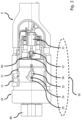
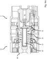
- the Figure 2 shows a longitudinal section of a highly integrated tank coupling K according to the invention.
- a coupling valve is arranged in the fluid passage 41 of the filler neck 10, which opens this fluid passage 41 by moving to the right for refueling.
- a sliding sleeve 11 can be moved in the longitudinal direction of the filler neck 10.
- the sliding sleeve 11 snaps in the direction of the tank nipple 80 under spring action when the filler neck 10 is plugged onto it. This is because the sliding sleeve 11 is connected via a rotating pin-shaped driver 13 to an internal clamping sleeve 14, which is released when the filler neck 10 is plugged on.
- the coupling sensor 20 which is designed here as a pushbutton switch, engages in a recess 21 of the sliding sleeve 11 in order to signal the coupled state of the filler neck 10 to the control unit 100 via an electrical line 101.
- the sliding sleeve 11 When the filler neck 10 is closed off from the tank nipple 80, the sliding sleeve 11 must be pulled back from the tank nipple 80 in order to release the connection created above between the tank coupling K and the tank nipple 80. This is because the clamping sleeve 14 allows the holding elements 12 to move radially outwards again and the filler neck 10 is released again. At the same time, the clamping sleeve 14 and thus also the sliding sleeve 11 can be locked again by the locking elements because the spring sleeve 15 has been moved back to the left.
- the concept of such a coupling is also called push-pull and requires two-handed operation of the tank coupling K.
- the internal control unit 100 is arranged in a handle area 19 of the tank coupling K and is designed to receive, process and output signals.
- a power supply U of the control unit 100 is switched on and the opening of the refueling valve 40 is activated.
- a combined display and control element 110, 120 electrically connected to the control unit 100 indicates a refueling status, for example optically by means of a light source that illuminates in different colors.
- the start and end of the refueling process can be influenced by the user via the control element 120, here for example a push button.
- the tank coupling K also has a data interface 130 arranged in the area of its filler neck 10 for communication with a vehicle, as well as a (nitrogen) purge system for flushing the coupled filler neck 10.
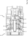
- the Figure 3 shows a longitudinal section view of the tank coupling K according to the invention of Figure 2 with a locking mechanism 30 comprising an SMA actuator 31, which, via a locking pin 32, brings a pivoting bolt 33 into abutment against a pin-shaped driver 34 running with the sliding sleeve 11.
- the driver 34 which is connected to the Figure 2
- the locking pin 32 which can be identical to the driver 13 shown, is secured in a U-shaped receptacle 35 to prevent it from slipping out of the locking position.
- the locking pin 32 has a circumferential, preferably one-sided conical shoulder 36, the position of which is continuously detected by a locking sensor 60, which is designed here as a pushbutton switch.
- the coupling sensor 20 engages in a recess 21 in the sliding sleeve 11 of the filler neck 10 when the latter is attached to the tank nipple 80. By engaging in the recess 21, the coupling sensor 20 detects the coupling state of the filler neck 10 as coupled.
- FIGS. 4a to 4i illustrate individual processes when connecting a tank coupling K according to the invention to a vehicle-side tank nipple 80.
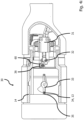
- the Figure 4a shows a longitudinal section view of a tank coupling K according to the invention of Figure 2 in the non-connected state.
- the valve cone 42 of the coupling valve is in a closed position and, due to the pre-tension of a spring 43, prevents ambient air from entering the fluid passage 41 of the filler neck 10.
- a spring sleeve 15 is also in the closed position and prevents the holding elements 12 and the balls 16 from falling radially inwards.
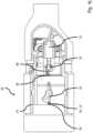
- the Figure 4b shows a longitudinal section view of the tank coupling K according to the invention of Figure 4a when plugged onto the vehicle-side tank nipple 80. This causes it to move into the connection channel of the filler neck 10.
- the spring sleeve 15 makes the first axial contact and the tank nipple 80 moves this further to the right as the filler neck 10 is plugged on.
- the Figure 4c shows a longitudinal section view of the tank coupling K according to the invention of Figure 4a when opening the fluid passage 41 of the filler neck 10.
- the Figure 4d shows a longitudinal section view of the tank coupling K according to the invention of Figure 4a when the fluid passage 41 of the filler neck 10 is completely open.
- the tank nipple 80 and the spring sleeve 15 reach their common end stop. This also completely opens the valve cone 42.
- the holding elements 12 fall partially due to gravity into a circumferential groove 81 of the tank nipple 80.
- the Figure 4e shows a longitudinal section view of the tank coupling K according to the invention of Figure 4a in the locked state on the vehicle-side tank nipple 80.
- the sliding sleeve 11 is pushed forwards in the direction of the tank nipple 80 by a spring 17.
- the drivers 13 transfer this movement to the clamping sleeve 14, whereby the holding elements 12 are pressed into the groove 81 of the tank nipple 80 independently of gravity.
- the Figure 4f shows a longitudinal section view of the tank coupling K according to the invention of Figure 4a when locking onto the vehicle-side tank nipple 80.
- the further movement of the sliding sleeve 11 into its end position locks the holding elements 12 and thus enables a positive-locking load-bearing connection.
- the Figure 4g shows a longitudinal section of the tank coupling K according to the invention of Figure 4a in the locked state on the vehicle-side tank nipple 80, in which the sliding sleeve 11, when it reaches its end position, actuates the coupling sensor 20 (not shown here), for example a push button switch, which generates a signal which is received by the control unit 100 as confirmation of a correct connection.
- the control unit 100 confirms this state to the filling station T.
- the gas station T responds with another command to the control unit 100, which controls an SMA actuator 31 (shown in Figure 4h ) is activated within the tank coupling K, which prevents unintentional or improper operation of the same.
- the control unit 100 sends a further confirmation signal to the petrol station, which then releases the refueling process.
- the Figure 4h shows a longitudinal section of the tank coupling K according to the invention of Figure 4a with closed locking mechanism 30, which secures the SMA actuator 31, the locking pin 32 with a circumferential shoulder 36, the pivot bolt 33 and the U-shaped receptacle 35 of the driver 34, which is here implemented by the driver 13 of Figure 3a.
- the gas station sends a signal to the electronic control 100, which then supplies power to the SMA actuator 31. Its FGL (shape memory alloy) wire contracts and thus triggers the locking mechanism 30.
- FGL shape memory alloy
- the Figure 4i shows a longitudinal section of the tank coupling K according to the invention of Figure 4a in refueling position.
- a circumferential shoulder 36 on the locking pin 32 designed as a conical cone, closes a locking sensor 60 designed as a push button switch, the signal of which is continuously monitored by the control unit 100. If this signal fails during refueling, it generates and sends an error message to the filling station T, after which the refueling process must be interrupted.
- the control unit 100 activates a magnetically driven pilot valve on a 3-port / 2-switch position valve, which starts the refueling process.
- the control unit 100 sends a start signal to the filling station T, which in turn initiates the pressure build-up in the fluid passage 41' for refueling.
- FIGS. 4j to 4n illustrate individual processes when disconnecting a tank coupling K according to the invention from a vehicle-side tank nipple 80.
- the Figure 4j shows a longitudinal section of the tank coupling K according to the invention of Figure 4a after opening the lock 30.
- the refueling process can be ended by pressing the push button 120 in the handle again or by the petrol station control itself.
- the control unit 100 recognizes the command and switches off the pilot control of the 3-connection / 2-switching position valve, which returns it to its starting position and switches to venting the refueling line 41'.
- a pressure sensor 52 on the tank coupling K itself or in the petrol station area reports to the petrol station T when only a pressure of 5 bar or less is present in the vent line 41".
- the petrol station T sends a termination signal to the control unit 100, which then deactivates the SMA actuator 31.
- the blockage of the driver 13 is then removed via the lock 30.
- the Figure 4k shows a longitudinal section view of the tank coupling K according to the invention of Figure 4a when unlocking the vehicle-side tank nipple 80.
- the user pulls the Sliding sleeve 11 moves back and thus also the clamping sleeve 14 via the drivers 13.
- the holding elements 12 and the balls 16 can move radially outwards. This allows the tank nipple 80 and the spring sleeve 15 to move freely.
- the Figure 4j as described in the following figures, locking components 31, 32, 33, 34 and 36 can be seen in a side view.
- the Figure 4l shows a longitudinal section view of the tank coupling K according to the invention of Figure 4a when closing the fluid passage 41 of the filler neck 10.
- the spring sleeve 15 presses the tank nipple 80 out of the tank coupling K. This assists the user in closing, whereby he must apply the main force.
- the valve cone 42 begins to move towards the valve seat 45 and close the fluid passage 41 of the filler neck 10.
- FIG 4m shows a longitudinal section view of the tank coupling K according to the invention of Figure 4a with the fluid passage 41 of the filler neck 10 completely closed by the closed valve cone 42.
- the valve stem 44 is no longer in engagement with the sealing package of the tank nipple 80.
- the spring sleeve 15 continues to push the tank nipple 80 out of the tank coupling K.
- the Figure 4n shows a longitudinal section view of the tank coupling K according to the invention of Figure 2 when pulling off the vehicle-side tank nipple 80.
- the spring sleeve 15 reaches its end stop. From now on, the user must pull off the tank coupling K independently. The mechanism has returned to its starting position.
- FIGS. 5a to 5e represent different types of refueling valves as they can be used in a refueling system B according to the invention.
- the Figure 5a shows a schematic cross-sectional view of a first type of main valve in the refueling system B according to the invention for a pressure of approximately 8.75 x 10 7 N/m2 (875 bar).
- This represents a 3-port / 2-switching position valve, with a fluid passage 41, which can be switched between a fluid passage for refueling 41' and a fluid passage for venting 41" via a refueling valve 40 and a vent valve 41' coupled thereto.
- An SMA actuator 70 is provided for opening and closing the refueling valve 40 or the vent valve 41', which opens the refueling valve 40 against a return spring and the vent valve 41' closes against the force of this spring, and vice versa.
- a spring wire of the SMA actuator 70 is axially dynamically sealed, whereby the spring wire and a respective shut-off body of the refueling valve 40 and vent valve 40' are firmly connected to one another and mounted in a cardanic manner.
- the return spring enables an NC version.
- the slide valve design has the advantage that the forces required for switching are significantly reduced, especially when the slide elements are made of ceramic. This reduces the friction coefficients many times over compared to metal. In addition, ceramic elements are extremely wear-resistant and almost insensitive to foreign and dirt particles.
- the petrol station operator also saves a significant amount of H2 after each refueling process, which is returned to the company's own H2 tank systems. If the petrol station operator has its own vent line, the main valve described here could also be operated as a 2-port / 2-switch position valve.
- the Figure 5b shows a schematic cross-sectional view of a second type of main valve in a refueling system B according to the invention for a pressure of approximately 8.75 x 10 7 N/m2 (875 bar).
- This main valve is designed as a 3-port / 2-switching position valve, with a refueling valve 40 and a vent valve 40', which can be opened and closed alternately.
- the valves 40, 40' are driven by an electric motor 70', the shut-off bodies of the valves 40, 40' being firmly connected to one another and mounted in a gimbal manner via a non-self-holding motor spindle, the motor spindle not being self-holding.
- the electric motor 70' is preferably designed as a stepper motor and is supplied with power via a GTMS cable feedthrough 71. This allows the electric motor 70' to be arranged inside the main valve and to be encapsulated against the environment for a long time and without loss of performance, even at high pressures of up to 2.00 x 10 7 N/m2 (2000 bar), which would not be possible with the plastic seals that would otherwise be required, in particular dynamic plastic seals.
- the Figure 5c shows a schematic cross-sectional view of a third type of main valve in a refueling system B according to the invention for a pressure of approximately 8.75 ⁇ 10 7 N/m2 (875 bar).
- This main valve is designed here as a 2-port / 2-switching position valve, with a refueling valve 40 that can be opened and closed for refueling, so that the fluid passage for refueling 41' can communicate fluidically with the fluid passage 41 of the filler neck 10.
- the refueling valve 40 is driven by an electric motor 70', which is placed on the outside of the main valve, which subsequently requires a rotary feedthrough 71 for the motor spindle with dynamic plastic seals.
- a shut-off body of the valve 40 is firmly connected to the non-self-holding motor spindle and is cardanically mounted, whereby the motor spindle is not self-holding.
- This main valve is intended to be used in particular where a filling station T already provides its own vent line, which is opened before connecting (removing) a tank coupling K from the vehicle-side tank nipple 80.
- This provides a particularly inexpensive alternative to a main valve, which could also be mounted with a simple leg spring 72.
- the Figure 5d shows a schematic cross-sectional view of a fourth type of main valve in a refueling system B according to the invention for a pressure of approximately 8.75 ⁇ 10 7 N/m2 (875 bar).
- This main valve corresponds to the Figure 5c , but is designed as a 3-port / 2-switch position valve, with a refueling valve 40 and an additional vent valve 40', which can be opened and closed alternately.
- This main valve is a low-cost alternative in a situation in which no venting of the fluid passage 41 of the filler neck 10 at the filling station is possible.
- the Figure 5e shows a schematic cross-sectional view of a fifth type of main valve in a refueling system B according to the invention for a pressure of approximately 8.75 ⁇ 10 7 N/m2 (875 bar).
- This main valve also has a pilot valve 40" for controlling the refueling valve 40, which opens and closes alternately with a vent valve 40'.
- This type of main valve requires a comparatively weak electric motor, so that a magnetic drive 70" is sufficient, which can also be placed on the outside of the main valve. What has already been said about the previous figures of a similar type applies to the interaction between the refueling valve 40 and the vent valve 40'.
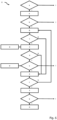
- the Figure 6 shows the sequence of a refueling method V according to the invention for a tank coupling K according to the invention.
- the individual steps and actions can be found in the list below. Time intervals can also be implemented between these steps, which give the user information on the status of the process and possibly also require confirmation, for example via the display 110 and the control element 120. This increases the transparency of the process and excludes potential user errors.
- Step action A Control unit in standby mode (power supply) B Close the lock C Open the refueling valve D User input / signal pressure or level sensor E Close the refueling valve and open the vent valve F Open the lock G control unit into the idle state (no power supply) I information output (confirmation or error) Step query a Tank coupling taken from a dispenser?
- step a first checks whether the tank coupling K has been removed from the dispenser of a gas station T. If this is the case (Y), in step A the control unit 100 is put into a standby state by energizing it. The energization can be triggered, for example, by a distance sensor 50, which detects the removal of the tank coupling K from the dispenser of the gas station T. The standby state of the control unit 100 can be signaled to a display 110 (I), which informs the user that the refueling system B is functioning properly. The user can then place a filler neck 10 of the tank coupling K onto a tank nipple 80, which is checked in step b.
- a display 110 I
- the correct placement of the filler neck 10 can also be signaled to the display 110 (I) in order to give the user feedback on the correct operation of the tank coupling K. If this is the case (Y), in step B the lock 30 of the tank coupling K and the tank nipple is closed.
- step C a refueling valve 40 can be opened in response to a user input (start of refueling) D.
- the check in step c is carried out continuously from the beginning to the end of refueling, i.e. between steps C (open refueling valve) and E (close refueling valve), in order to provide security against unintentional unlocking of the tank coupling K from the tank nipple 80, particularly in this critical process section. If, however, a faulty or not closed lock 30 is detected in step c (N), the system proceeds to step E, in which it is ensured that the refueling valve 40 is closed and a vent valve 40' is open.
- step d it is finally checked whether the refueling valve 40 has been opened and only in the case where this is not the case (N) is it passed on to step E, in which it is ensured that the refueling valve 40 is closed and a vent valve 40' is open. Otherwise (Y), step e is initiated, in which it is checked whether the refueling has ended by a user input (end of refueling) or a signal from a pressure or level sensor (tank full) D. Such a termination can also be signaled to the display 110 (I) in order to give the user certainty about the refueling status. The refueling of a vehicle continues until it is terminated.
- step E the refueling valve 40 is closed and the vent valve 40' is opened in order to be able to safely remove the tank coupling K from the tank nipple 80.
- step f Whether the refueling valve 40 is closed and the vent valve 40' is open is checked in step f. If this is not the case (N), the refueling process V jumps back to step B to be on the safe side, in which the lock 30 is closed and in step c it is also checked whether this is the case. This prevents the pressure-loaded tank coupling K from being pulled off the tank nipple 80. If, on the other hand, it is ensured that the refueling valve 40 is closed and the vent valve 40' is open (Y), the process continues to step F, in which the lock 30 is opened. The user can then pull the tank coupling K off the tank nipple 80 and reattach it to the dispenser of the gas station T, which is checked in step g.
- Correct attachment of the tank coupling K to the dispenser can also be signaled to the display 110 (I) in order to give the user certainty that the refueling process has been completed correctly. If the tank coupling K is reattached to the dispenser (Y), the control unit 100 is de-energized again in the final step G in order to save energy.
- the above refueling process is simple, reliable and safe to carry out and represents only a basic process as it can be implemented in a control system S according to the invention, for example in software.
- the refueling process can have further steps that are required to coordinate the individual functional components.
- the control system S comprises a control unit 100 which is designed like a computer and comprises at least one main processor, a working memory, a program and data memory and a communication interface, in particular based on an I2C (Inter-Integrated-Circuit) bus.
- the control unit 100 can also be designed to send, receive and process data from a data interface of the tank coupling K.
- the refueling method may take the form of a computer program product accessible from a computer-usable or computer-readable medium that provides program code for use by or in connection with a computer or any instruction execution system.
- a computer-usable or computer-readable medium may be any device that can contain, store, transmit, distribute, or transport the program for use by or in connection with the instruction execution system, apparatus, or device.
- the medium may be an electronic, magnetic, optical, electromagnetic, infrared, or semiconductor system (or apparatus or device), or a computer network.
- Examples of a computer-readable medium include semiconductor or solid-state memory, magnetic tape, a removable computer diskette, random access memory (RAM), read-only memory (ROM), a rigid magnetic disk, and an optical disk or the Internet. Current examples of optical disks include compact disk, read-only memory (CD-ROM), read/write (CD-RW), and DVD.
Landscapes
- Engineering & Computer Science (AREA)
- Mechanical Engineering (AREA)
- General Engineering & Computer Science (AREA)
- Cooling, Air Intake And Gas Exhaust, And Fuel Tank Arrangements In Propulsion Units (AREA)
Priority Applications (1)
| Application Number | Priority Date | Filing Date | Title |
|---|---|---|---|
| EP23187758.0A EP4497989A1 (fr) | 2023-07-26 | 2023-07-26 | Raccord de carburant, système de ravitaillement, système de contrôle et procédure de ravitaillement |
Applications Claiming Priority (1)
| Application Number | Priority Date | Filing Date | Title |
|---|---|---|---|
| EP23187758.0A EP4497989A1 (fr) | 2023-07-26 | 2023-07-26 | Raccord de carburant, système de ravitaillement, système de contrôle et procédure de ravitaillement |
Publications (1)
| Publication Number | Publication Date |
|---|---|
| EP4497989A1 true EP4497989A1 (fr) | 2025-01-29 |
Family
ID=87474146
Family Applications (1)
| Application Number | Title | Priority Date | Filing Date |
|---|---|---|---|
| EP23187758.0A Withdrawn EP4497989A1 (fr) | 2023-07-26 | 2023-07-26 | Raccord de carburant, système de ravitaillement, système de contrôle et procédure de ravitaillement |
Country Status (1)
| Country | Link |
|---|---|
| EP (1) | EP4497989A1 (fr) |
Citations (6)
| Publication number | Priority date | Publication date | Assignee | Title |
|---|---|---|---|---|
| JP2008232418A (ja) * | 2007-02-21 | 2008-10-02 | Tokiko Techno Kk | ガス充填装置 |
| WO2012021642A2 (fr) * | 2010-08-10 | 2012-02-16 | Konishi Howard M | Raccord à fixation rapide |
| US20170159886A1 (en) * | 2015-12-03 | 2017-06-08 | Engineered Controls International, Llc | Low emission nozzles and receptacles |
| CN111664350A (zh) * | 2020-07-01 | 2020-09-15 | 优普能源技术有限公司 | 一种单管加氢枪及其充装释压系统 |
| EP3428505B1 (fr) * | 2017-07-11 | 2021-05-26 | Tatsuno Corporation | Appareil de remplissage |
| EP3608574B1 (fr) * | 2017-04-07 | 2022-06-15 | Nitto Kohki Co., Ltd. | Élément de raccord de tuyau femelle ayant un terminal de communication |
-
2023
- 2023-07-26 EP EP23187758.0A patent/EP4497989A1/fr not_active Withdrawn
Patent Citations (6)
| Publication number | Priority date | Publication date | Assignee | Title |
|---|---|---|---|---|
| JP2008232418A (ja) * | 2007-02-21 | 2008-10-02 | Tokiko Techno Kk | ガス充填装置 |
| WO2012021642A2 (fr) * | 2010-08-10 | 2012-02-16 | Konishi Howard M | Raccord à fixation rapide |
| US20170159886A1 (en) * | 2015-12-03 | 2017-06-08 | Engineered Controls International, Llc | Low emission nozzles and receptacles |
| EP3608574B1 (fr) * | 2017-04-07 | 2022-06-15 | Nitto Kohki Co., Ltd. | Élément de raccord de tuyau femelle ayant un terminal de communication |
| EP3428505B1 (fr) * | 2017-07-11 | 2021-05-26 | Tatsuno Corporation | Appareil de remplissage |
| CN111664350A (zh) * | 2020-07-01 | 2020-09-15 | 优普能源技术有限公司 | 一种单管加氢枪及其充装释压系统 |
Similar Documents
| Publication | Publication Date | Title |
|---|---|---|
| EP3341253B1 (fr) | Frein de parquage électrique avec source auxiliaire d'énergie | |
| EP2300292B1 (fr) | Système automatique de freinage | |
| EP3698992A1 (fr) | Dispositif de liaison, système de liaison ainsi que semi-remorque | |
| EP1759131A1 (fr) | Dispositif actionneur permettant de commander un mecanisme de verrouillage | |
| DE2629379A1 (de) | Automatische kupplung fuer brems- und elektrofunktionen zwischen teilen einer fahrzeugkombination | |
| EP1382469A2 (fr) | Electrovanne pour véhicule utilitaire à suspension pneumatique | |
| DE4035453C2 (de) | Schnellverschlußkupplung für hydraulische Bremssysteme, insbesondere Anhängerkupplungen | |
| EP0800234B1 (fr) | Raccord à fiches | |
| EP4497989A1 (fr) | Raccord de carburant, système de ravitaillement, système de contrôle et procédure de ravitaillement | |
| DE19914318C2 (de) | Vorrichtung zum Kuppeln von hydraulischen Leitungen | |
| DE102004014461A1 (de) | Rohrkupplung | |
| EP3781857A1 (fr) | Raccord et procédé de transmission de fluides | |
| DE69300585T2 (de) | Sicherheitsverriegelung zwischen Kupplung und Druckluftbremse. | |
| EP1162090B1 (fr) | Dispositif d'attelage et un véhicule tracteur avec dispositif d'attelage | |
| DE69222155T2 (de) | Verbindungsvorrichtung für flüssigkeitszufur | |
| DE2935741A1 (de) | Steuereinrichtung zur betaetigung einer fahrzeugbremse | |
| EP0612645A1 (fr) | Frein à air comprimé pour véhicules sur rails | |
| EP2925577B1 (fr) | Ensemble soupape pour un système de freinage électropneumatique | |
| EP2552716B1 (fr) | Agencement pour l'accouplement par air comprimé d'une remorque à un véhicule tracteur | |
| DE3100616A1 (de) | Bremsbetaetigungsvorrichtung fuer fahrzeug-radbremsen | |
| DE102024114067A1 (de) | Verfahren zur Einstellung einer Digitale Automatische Kupplung ( DAK) mit einem Aktuator für ein Schienenfahrzeug | |
| EP4707000A1 (fr) | Attelage, système de liaison et procédé d'accouplement d'un véhicule tracté à un véhicule tracté | |
| EP4222410B1 (fr) | Dispositif d'accouplement et dispositif de cryo-ravitaillement | |
| DE202023103325U1 (de) | Sattelkupplung mit fremdkraftbetätigtem Verschluss | |
| EP0056071B1 (fr) | Raccord à haute pression |
Legal Events
| Date | Code | Title | Description |
|---|---|---|---|
| PUAI | Public reference made under article 153(3) epc to a published international application that has entered the european phase |
Free format text: ORIGINAL CODE: 0009012 |
|
| STAA | Information on the status of an ep patent application or granted ep patent |
Free format text: STATUS: THE APPLICATION HAS BEEN PUBLISHED |
|
| AK | Designated contracting states |
Kind code of ref document: A1 Designated state(s): AL AT BE BG CH CY CZ DE DK EE ES FI FR GB GR HR HU IE IS IT LI LT LU LV MC ME MK MT NL NO PL PT RO RS SE SI SK SM TR |
|
| STAA | Information on the status of an ep patent application or granted ep patent |
Free format text: STATUS: THE APPLICATION IS DEEMED TO BE WITHDRAWN |
|
| 18D | Application deemed to be withdrawn |
Effective date: 20250730 |