EP4498035A1 - Dispositif de mesure pour l'étalonnage d'un système de détection d'un véhicule - Google Patents
Dispositif de mesure pour l'étalonnage d'un système de détection d'un véhicule Download PDFInfo
- Publication number
- EP4498035A1 EP4498035A1 EP24189981.4A EP24189981A EP4498035A1 EP 4498035 A1 EP4498035 A1 EP 4498035A1 EP 24189981 A EP24189981 A EP 24189981A EP 4498035 A1 EP4498035 A1 EP 4498035A1
- Authority
- EP
- European Patent Office
- Prior art keywords
- vehicle
- measuring
- camera
- sensor
- mark
- Prior art date
- Legal status (The legal status is an assumption and is not a legal conclusion. Google has not performed a legal analysis and makes no representation as to the accuracy of the status listed.)
- Pending
Links
Images

Classifications
-
- G—PHYSICS
- G01—MEASURING; TESTING
- G01B—MEASURING LENGTH, THICKNESS OR SIMILAR LINEAR DIMENSIONS; MEASURING ANGLES; MEASURING AREAS; MEASURING IRREGULARITIES OF SURFACES OR CONTOURS
- G01B11/00—Measuring arrangements characterised by the use of optical techniques
- G01B11/002—Measuring arrangements characterised by the use of optical techniques for measuring two or more coordinates
-
- G—PHYSICS
- G01—MEASURING; TESTING
- G01B—MEASURING LENGTH, THICKNESS OR SIMILAR LINEAR DIMENSIONS; MEASURING ANGLES; MEASURING AREAS; MEASURING IRREGULARITIES OF SURFACES OR CONTOURS
- G01B11/00—Measuring arrangements characterised by the use of optical techniques
- G01B11/26—Measuring arrangements characterised by the use of optical techniques for measuring angles or tapers; for testing the alignment of axes
- G01B11/275—Measuring arrangements characterised by the use of optical techniques for measuring angles or tapers; for testing the alignment of axes for testing wheel alignment
- G01B11/2755—Measuring arrangements characterised by the use of optical techniques for measuring angles or tapers; for testing the alignment of axes for testing wheel alignment using photoelectric detection means
-
- G—PHYSICS
- G01—MEASURING; TESTING
- G01S—RADIO DIRECTION-FINDING; RADIO NAVIGATION; DETERMINING DISTANCE OR VELOCITY BY USE OF RADIO WAVES; LOCATING OR PRESENCE-DETECTING BY USE OF THE REFLECTION OR RERADIATION OF RADIO WAVES; ANALOGOUS ARRANGEMENTS USING OTHER WAVES
- G01S7/00—Details of systems according to groups G01S13/00, G01S15/00, G01S17/00
- G01S7/48—Details of systems according to groups G01S13/00, G01S15/00, G01S17/00 of systems according to group G01S17/00
- G01S7/497—Means for monitoring or calibrating
- G01S7/4972—Alignment of sensor
-
- G—PHYSICS
- G01—MEASURING; TESTING
- G01B—MEASURING LENGTH, THICKNESS OR SIMILAR LINEAR DIMENSIONS; MEASURING ANGLES; MEASURING AREAS; MEASURING IRREGULARITIES OF SURFACES OR CONTOURS
- G01B2210/00—Aspects not specifically covered by any group under G01B, e.g. of wheel alignment, caliper-like sensors
- G01B2210/10—Wheel alignment
- G01B2210/14—One or more cameras or other optical devices capable of acquiring a two-dimensional image
- G01B2210/143—One or more cameras on each side of a vehicle in the main embodiment
-
- G—PHYSICS
- G01—MEASURING; TESTING
- G01S—RADIO DIRECTION-FINDING; RADIO NAVIGATION; DETERMINING DISTANCE OR VELOCITY BY USE OF RADIO WAVES; LOCATING OR PRESENCE-DETECTING BY USE OF THE REFLECTION OR RERADIATION OF RADIO WAVES; ANALOGOUS ARRANGEMENTS USING OTHER WAVES
- G01S13/00—Systems using the reflection or reradiation of radio waves, e.g. radar systems; Analogous systems using reflection or reradiation of waves whose nature or wavelength is irrelevant or unspecified
- G01S13/88—Radar or analogous systems specially adapted for specific applications
- G01S13/93—Radar or analogous systems specially adapted for specific applications for anti-collision purposes
- G01S13/931—Radar or analogous systems specially adapted for specific applications for anti-collision purposes of land vehicles
-
- G—PHYSICS
- G01—MEASURING; TESTING
- G01S—RADIO DIRECTION-FINDING; RADIO NAVIGATION; DETERMINING DISTANCE OR VELOCITY BY USE OF RADIO WAVES; LOCATING OR PRESENCE-DETECTING BY USE OF THE REFLECTION OR RERADIATION OF RADIO WAVES; ANALOGOUS ARRANGEMENTS USING OTHER WAVES
- G01S17/00—Systems using the reflection or reradiation of electromagnetic waves other than radio waves, e.g. lidar systems
- G01S17/88—Lidar systems specially adapted for specific applications
- G01S17/93—Lidar systems specially adapted for specific applications for anti-collision purposes
- G01S17/931—Lidar systems specially adapted for specific applications for anti-collision purposes of land vehicles
-
- G—PHYSICS
- G01—MEASURING; TESTING
- G01S—RADIO DIRECTION-FINDING; RADIO NAVIGATION; DETERMINING DISTANCE OR VELOCITY BY USE OF RADIO WAVES; LOCATING OR PRESENCE-DETECTING BY USE OF THE REFLECTION OR RERADIATION OF RADIO WAVES; ANALOGOUS ARRANGEMENTS USING OTHER WAVES
- G01S7/00—Details of systems according to groups G01S13/00, G01S15/00, G01S17/00
- G01S7/02—Details of systems according to groups G01S13/00, G01S15/00, G01S17/00 of systems according to group G01S13/00
- G01S7/40—Means for monitoring or calibrating
- G01S7/4004—Means for monitoring or calibrating of parts of a radar system
- G01S7/4026—Antenna boresight
- G01S7/403—Antenna boresight in azimuth, i.e. in the horizontal plane
Definitions
- the invention relates to a measuring arrangement and a method for calibrating a sensor of a vehicle.
- Vehicles with driver assistance systems and/or with the ability to perform at least partially autonomous driving functions have sensors that can be used to detect the vehicle's surroundings.
- sensors include radar sensors, cameras, LIDAR sensors, ultrasonic sensors, etc.
- a sensor measuring mark which is to be detected by the sensor to be calibrated, must be placed in the vicinity of the vehicle at a specified position, hereinafter referred to as the target position. After placement, the sensor can be calibrated in a further step.
- measuring marks Before the measuring mark is placed, measuring marks must be measured on the vehicle itself, for example measuring marks arranged on the wheels or the vehicle body, in order to position the sensor measuring mark in a required position relative to the vehicle. For example, it may be necessary to position the sensor measuring mark depending on vehicle reference information that can be determined from the measuring marks arranged on the vehicle, for example the geometric driving axis.
- the problem with the known measuring arrangements is that the placement of the measuring mark is very complex, since it often has to be placed by manual measurement and is difficult to document.
- the invention relates to a measuring arrangement for calibrating a sensor of a vehicle.
- the measuring arrangement comprises a measuring station with a measuring station plane, by which a first and second half-space are delimited from one another.
- the measuring station plane is in particular a vertical plane, the normal of which runs in the direction of the central longitudinal axis of the vehicle to be measured.
- the measuring station comprises a first and a second camera, which are arranged at the measuring station in such a way that an area of the first half-space can be captured by the first and second cameras.
- the measuring station is designed to be arranged in front of or behind the vehicle. In a first measuring situation, the vehicle to be measured can be located in the first half-space.
- the first half-space is the half-space facing away from the vehicle to be measured.
- the measuring station has at least one third camera, which is arranged at the measuring station in such a way that the detection range of the third camera is in the second half-space.
- the detection range of the third camera lies at least largely in the half-space in which the vehicle to be measured is not located.
- the detection range of the third camera lies at least largely in the half-space in which the vehicle to be measured is also located.
- the main technical advantage of the measuring arrangement is that the third camera extends the detection range of the measuring station, so that, for example, an area of space facing away from the vehicle to be measured can be detected, in which a sensor measuring mark can be positioned, by means of which a sensor that detects an area of space in front of or behind the vehicle can be calibrated.
- the third camera can be used to arrange the sensor measuring mark at a desired target position that is defined relative to vehicle reference information, and the sensor can then be calibrated using this sensor measuring mark.
- the vehicle reference information can, for example, be the geometric driving axis of the vehicle or information related to the vehicle body, for example body center information or the central longitudinal axis of the vehicle. This enables a technically simple and recordable arrangement of the sensor measuring mark and sensor calibration.
- the first camera has a first detection area and the second camera has a second detection area, each with a detection area center axis.
- the detection area center axes protrude from the measuring station plane to a first side in relation to the measuring station plane.
- the third camera has a third detection area with a third detection area center axis that protrudes from the measuring station plane to a second side, which is opposite the first side.
- the first and second cameras are arranged on a horizontally extending measuring bar and are spaced apart from one another in such a way that the first camera captures a first area to the left of the vehicle and the second camera captures an area opposite the first area to the right of the vehicle.
- the first and second cameras can thus capture measuring marks that are arranged on the wheels of the vehicle in order to capture the position and orientation of the wheels and thus vehicle reference information, such as the geometric driving axis of the vehicle.
- the third camera is designed to capture a rear area that is located behind the measuring station and faces away from the vehicle to be measured.
- the third camera has a detection area center axis that runs perpendicular to the measuring station plane. This means that the third camera can be used to cover areas in front of and/or behind the vehicle to be measured, in which measuring marks are to be placed for calibrating sensors that capture the environment in front of or behind the vehicle.
- the measuring arrangement has a computer unit with a program.
- the program is designed to capture image information from measuring marks arranged on the wheels of the vehicle using the first and second cameras and to calculate information on the position and alignment of the wheels of the vehicle based thereon.
- the information on the position and alignment of the wheels of the vehicle Vehicle reference information for example the geometric driving axis of the vehicle, is calculated.
- the program is also designed to calculate position correction information for a sensor measuring mark that is used to calibrate a sensor of the vehicle that detects an environmental area in front of and/or behind the vehicle, based on the image information provided by the third camera and that contains this sensor measuring mark. This makes it possible to use the measuring arrangement to precisely position the sensor measuring mark, by means of which the vehicle's sensor is calibrated, relative to the vehicle.
- the measuring arrangement has a computer unit with a program that is designed to capture image information from measuring marks that are arranged in side areas of the body of the vehicle using the first and second cameras and to calculate vehicle reference information based thereon.
- the program is also designed to calculate position correction information for a sensor measuring mark that is used to calibrate a sensor of the vehicle that detects an environmental area in front of and/or behind the vehicle, based on the image information provided by the third camera and that contains this sensor measuring mark, and the vehicle reference information.
- This means that measuring marks arranged on the body can also be used by means of the measuring arrangement to position a sensor measuring mark that is to be arranged centrally in front of or behind the vehicle.
- the measuring arrangement comprises a computer unit with a program, wherein the program is designed to generate image information from measuring marks which are located at one or more predetermined positions on the vehicle, in particular arranged on the vehicle body, using the third camera, and to calculate vehicle reference information based thereon.
- the program is also designed to calculate position correction information for a sensor measuring mark that is used to calibrate a sensor of the vehicle that detects an environmental area in front of and/or behind the vehicle, based on the image information provided by the first and/or second camera and that contains this sensor measuring mark.
- a measuring mark arranged centrally on the vehicle body can thus be detected using the third camera, and the sensor measuring mark can be correctly positioned by the first and/or second camera.
- the program has target position information of the sensor measuring mark.
- the position correction information indicates how the position and/or orientation of the sensor measuring mark must be changed in order to ensure that the sensor measuring mark assumes a target position required for calibrating the vehicle's sensor.
- a position deviation is determined by comparing the target position (defined by the target position information) with the current actual position, and the position correction information is instructions to a person positioning the sensor measuring mark on how the position of the sensor measuring mark must be changed in order to arrange it at the target position.
- the program of the computer unit has information on the position of the third camera relative to the position of the first and second cameras. Due to the known local relationship between the first and second cameras and the third Camera can compensate for position differences between the first and second camera and the third camera.
- the method offers the advantage that the measuring arrangement enables a technically simple and exact positioning of the sensor measuring mark according to the calculated vehicle reference information.
- a plurality of measuring marks arranged on the wheels of the vehicle are recorded by means of the first and second cameras.
- the vehicle reference information includes the geometric driving axis of the vehicle or information derived therefrom. This allows the sensor measuring mark to be positioned based on the geometric driving axis of the vehicle, which is advantageous since the sensor to be calibrated also often has to be adjusted in relation to the geometric driving axis.
- a plurality of measuring marks arranged on the body of the vehicle are detected by means of the first and second cameras.
- the vehicle reference information includes body center information of the vehicle or information derived therefrom, which is determined based on the position and orientation of the measuring marks arranged on the body. This allows the sensor measuring mark to be positioned based on the body center information of the vehicle or a value derived therefrom, which is advantageous because the sensor to be calibrated must also be partially adjusted in relation to the body center of the vehicle that has the sensor.
- At least one measuring mark arranged on the body of the vehicle is detected by means of the third camera.
- the vehicle reference information comprises body center information of the vehicle or information derived therefrom, which is determined based on the position and orientation of the at least one measuring mark arranged on the body of the vehicle.
- the measuring arrangement can thus also be operated in an inverse direction, i.e. the body center information can be calculated from the image information of a measuring mark arranged on the vehicle body, which is detected with the third camera, and the sensor measuring mark can be placed in the target position based on the body center information using the image information from the first or second camera.
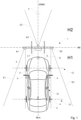
- the Fig. 1 shows a measuring arrangement 1 for calibrating a sensor S, for example a camera, a radar sensor or a LIDAR sensor of a vehicle 10.
- the measuring arrangement 1 comprises a measuring station 2, which is arranged, for example, in front of or behind a vehicle 10.
- the measuring station 2 is designed to detect measuring marks 4, which are arranged on the vehicle 10, and based on this To determine vehicle reference information that is required for the calibration of the sensor S.
- vehicle reference information can be, for example, the geometric driving axis or body center information, in particular the central longitudinal axis MLA of the vehicle 10.
- the measuring marks 4 can be measuring marks 4 arranged on the wheels 11 of the vehicle 10 in order to determine the geometric driving axis of the vehicle 10 or one or more measuring marks 4 that are arranged on the body of the vehicle 10 and based on which vehicle reference information, for example body center information, can be determined.
- vehicle reference information for example body center information
- the geometric driving axis can differ from the central longitudinal axis MLA of the vehicle 10.
- the central longitudinal axis MLA is the axis running centrally in the longitudinal direction through the vehicle body, i.e. the axis running between a front body center and a rear body center.
- the geometric driving axis can deviate from this central longitudinal axis MLA of the vehicle 10, in particular if one or more wheels 11 of a vehicle 10 are misaligned.
- At least one measuring mark 4 is assigned to a wheel 11, ie in a vehicle 10 with four wheels 11, there are two measuring marks 4 on the front axle 12 and two measuring marks 4 on the rear axle 13.
- the measuring marks 4 can be arranged on the wheels 11, for example, by means of measuring mark carriers.
- the measuring mark carriers are designed in particular for the clamping attachment of the measuring marks 4 to the rim of the vehicle 10.
- the measuring mark carrier is configured to space the measuring mark 4 relative to an outer wheel side surface, so that the measuring mark 4 protrudes laterally from the wheel 11.
- the measuring marks 4 on the wheels can be, for example, 3D measuring marks with a geometric pattern that can be captured by a camera and can be used to measure the wheel position in space (ie three-dimensional) as well as the angular wheel position (eg wheel camber).
- the geometric driving axis of the vehicle 10 can be determined via the position and orientation of the measuring marks 4 arranged on the wheels 11 and a sensor measuring mark 5 can be aligned relative to this geometric driving axis via the measuring arrangement.
- the measuring station 1 has a measuring bar 1.1, which is preferably horizontal or essentially horizontal and thus extends along the width of the vehicle.
- a first camera K1 and a second camera K2 are provided on the measuring bar 1.1, namely the first camera K1 in the left end area of the measuring bar 1.1 and the second camera K2 in the right end area of the measuring bar 1.1.
- the first camera K1 has a first detection area E1 and is designed to detect the measuring marks 4 arranged on the left side of the vehicle.
- the second camera K2 has a second detection area E2 and is designed to detect the measuring marks 4 arranged on the right side of the vehicle.
- These measuring marks can be measuring marks 4 arranged on the wheels 11 or measuring marks 4 arranged on the side body surfaces, as shown in Fig. 1 shown.
- the measuring arrangement 1 has a computer unit 3 on which a program for determining vehicle reference information is provided.
- the vehicle reference information can in particular include the geometric driving axis of the vehicle 10, body center information or information derived therefrom.
- the computer unit 3 is coupled to the first camera K1 and the second camera K2, so that the computer unit 3 Can receive image information from the first and second camera K1, K2.
- the image information from the first camera K1 contains the measuring marks 4 arranged on the left side of the vehicle on the wheels 11 or the vehicle body
- the image information from the second camera K2 contains the measuring marks 4 arranged on the right side of the vehicle on the wheels 11 or the vehicle body.
- the program of the computer unit 3 is designed to calculate the vehicle reference information based on the representations of the measuring marks 4 contained in the image information recorded by the cameras K1, K2.
- a sensor S is provided, for example, on the front.
- a sensor measuring mark 5 may be necessary, which must be positioned at a defined target position relative to the vehicle 10 in order to be able to carry out the calibration or adjustment.
- the sensor measuring mark 5 must often be provided at a distance from the vehicle 10 that is, for example, several meters (for example, 5 m in front of the vehicle).
- the measuring arrangement has a third camera K3. This is also provided at the measuring station 2, but has a detection direction that is opposite to the detection direction of the first and second cameras K1, K2.
- a measuring station level ME is defined by the measuring station 2.
- This measuring station level ME is divided the entire space into a first and a second half-space H1, H2.
- the vehicle 10 is provided in the first half-space H1.
- the detection areas E1, E2 of the first and second cameras K1, K2 are in the first half-space H1.
- the detection area E3 of the third camera K3, on the other hand, is at least predominantly in the second half-space H2, so that the third camera K3 can detect a spatial area facing away from the vehicle 10, which is in front of or behind the vehicle 10.
- the detection area E3 of the third camera K3 has a detection area center axis EBMA.
- This detection area center axis EBMA runs parallel or essentially parallel to the central longitudinal axis MLA of the vehicle 10.
- the third camera K3 therefore detects, for example, an area centrally in front of or behind the vehicle 10.
- Fig. 2 shows an alternative measuring arrangement 1, in which the measuring station 2 is compared to the Fig. 1 is arranged rotated by 180°.
- the detection range E3 of the third camera K3 is thus directed towards the vehicle 10 and the vehicle 10 is located in the second half-space H2, in which the detection range E3 also extends at least for the most part.
- the third camera K3 which is located centrally on the measuring beam, can capture a central front or rear area of the vehicle.
- Fig. 2 In the embodiment shown, two measuring marks 4 are arranged on the vehicle body, namely in the area of the A-pillars of the vehicle 10. These measuring marks 4 can be detected by the camera K3.
- the computer unit 3 can record the position and/or orientation of the measuring marks 4 and based on this Vehicle reference information is calculated, which includes, for example, the central longitudinal axis MLA. It is understood that the vehicle reference information can also include other or additional information. Based on this vehicle reference information, a sensor measuring mark 5 can then be positioned, which is to be arranged at a specific position in space relative to the vehicle 10, which has the sensor S. This sensor measuring mark 5 is arranged in the half-space H1 in which the vehicle 10 is not located.
- the actual position of the sensor measuring mark 5 is recorded by means of the first or second camera K1, K2.
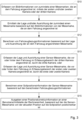
- image information from at least one measuring mark 4, which is arranged on the vehicle 10 is acquired by means of the first and/or second camera K1, K2 (see Fig. 1 ) or alternatively using the third camera K3 (see Fig. 2 ) (S10).
- the measuring marks 4 each have a geometric pattern.
- the position and/or orientation of the at least one measuring mark 4 is then determined by means of the computer unit 3 of the measuring station 2, based on the image information of the measuring mark 4, which is arranged on the vehicle (S11). This is preferably done by comparing the geometric pattern that was recorded by the respective camera K1, K2, K3 with a reference pattern stored in the computer unit or available there. For If the measuring mark 4 is arranged on a wheel 11 of the vehicle 10, the position and orientation of the wheel 11 relative to a reference point can be determined by the computer unit 3. If the measuring mark 4 is arranged on the body of the vehicle 10, the position and/or orientation of the body position at which the measuring mark is arranged can be determined relative to a reference point by the computer unit 3.
- vehicle reference information is calculated using the computer unit 3 of the measuring station 2 (S12).
- the vehicle reference information includes information about the vehicle 10 that is necessary for calibrating or adjusting the sensor S of the vehicle 10.
- An example of vehicle reference information is the geometric driving axis or the vehicle center axis MLA of the vehicle 10.
- this sensor measuring mark 5 can be arranged in front of or behind the vehicle 10 in the detection range E3 of the third camera K3.
- the sensor measuring mark 5 can be arranged in front of or behind the vehicle 10 in the detection range E1, E2 of the first or second camera K1, K2 (S13).
- the respective detection range E1, E2, E3 of the camera K1, K2, K3 with which the sensor measuring mark 5 is recorded is directed away from the vehicle 10.
- the computer unit 3 of the measuring station 2 calculates target position information of the sensor measuring mark 5 based on the vehicle reference information (S14).
- the Target position information indicates where the sensor measuring mark 5 should be located so that a sensor S of the vehicle 10 can be adjusted or calibrated using the sensor measuring mark 5.
- position correction information is output to a user interface of the computer unit 3, based on which the sensor measuring mark 5 can be positioned from the current position to the target position (S15).
- the user interface can be, for example, a graphical user interface, an acoustic user interface or a combination of both.
- the position correction information gives the workshop personnel an instruction as to the direction and how far the sensor measuring mark 5 must be repositioned and/or changed in orientation in order to reach the desired target position.
- the calibration and/or adjustment of the sensor S can be carried out.
- the measuring station 2 is preferably moved out of the line of sight between the sensor S and the sensor measuring mark 5 so that the sensor S can interact directly with the sensor measuring mark 5.
- the computer unit 3 is designed to log the process of positioning the sensor measuring mark 5 to the target position so that this and preferably also the calibration and/or adjustment process can be traced later.
Landscapes
- Physics & Mathematics (AREA)
- General Physics & Mathematics (AREA)
- Engineering & Computer Science (AREA)
- Computer Networks & Wireless Communication (AREA)
- Radar, Positioning & Navigation (AREA)
- Remote Sensing (AREA)
- Length Measuring Devices By Optical Means (AREA)
Applications Claiming Priority (1)
| Application Number | Priority Date | Filing Date | Title |
|---|---|---|---|
| DE102023120086.0A DE102023120086A1 (de) | 2023-07-28 | 2023-07-28 | Messanordnung zur Kalibrierung einer Sensorik eines Fahrzeugs |
Publications (1)
| Publication Number | Publication Date |
|---|---|
| EP4498035A1 true EP4498035A1 (fr) | 2025-01-29 |
Family
ID=91968848
Family Applications (1)
| Application Number | Title | Priority Date | Filing Date |
|---|---|---|---|
| EP24189981.4A Pending EP4498035A1 (fr) | 2023-07-28 | 2024-07-22 | Dispositif de mesure pour l'étalonnage d'un système de détection d'un véhicule |
Country Status (2)
| Country | Link |
|---|---|
| EP (1) | EP4498035A1 (fr) |
| DE (1) | DE102023120086A1 (fr) |
Citations (5)
| Publication number | Priority date | Publication date | Assignee | Title |
|---|---|---|---|---|
| DE102013001449A1 (de) * | 2012-09-10 | 2014-03-13 | Haweka Ag | Verfahren zur Justierung eines Abstandssensors an einem Fahrzeug und Messtraverse |
| EP2150772B1 (fr) * | 2007-04-18 | 2015-09-09 | Snap-on Incorporated | Procédé à utiliser avec un système d'alignement optique pour positionner une monture par rapport à un véhicule |
| DE102017213421A1 (de) * | 2017-08-02 | 2019-02-07 | Robert Bosch Gmbh | Verfahren und Vorrichtung zum Kalibrieren eines Referenztargets |
| US20200239010A1 (en) * | 2019-01-25 | 2020-07-30 | Nexion S.P.A. | Apparatus for calibrating an advanced driver assistance system sensor of a vehicle |
| CN116293254A (zh) * | 2023-03-06 | 2023-06-23 | 深圳市道通科技股份有限公司 | 一种横梁模块、车辆测量设备及校正方法 |
-
2023
- 2023-07-28 DE DE102023120086.0A patent/DE102023120086A1/de active Pending
-
2024
- 2024-07-22 EP EP24189981.4A patent/EP4498035A1/fr active Pending
Patent Citations (5)
| Publication number | Priority date | Publication date | Assignee | Title |
|---|---|---|---|---|
| EP2150772B1 (fr) * | 2007-04-18 | 2015-09-09 | Snap-on Incorporated | Procédé à utiliser avec un système d'alignement optique pour positionner une monture par rapport à un véhicule |
| DE102013001449A1 (de) * | 2012-09-10 | 2014-03-13 | Haweka Ag | Verfahren zur Justierung eines Abstandssensors an einem Fahrzeug und Messtraverse |
| DE102017213421A1 (de) * | 2017-08-02 | 2019-02-07 | Robert Bosch Gmbh | Verfahren und Vorrichtung zum Kalibrieren eines Referenztargets |
| US20200239010A1 (en) * | 2019-01-25 | 2020-07-30 | Nexion S.P.A. | Apparatus for calibrating an advanced driver assistance system sensor of a vehicle |
| CN116293254A (zh) * | 2023-03-06 | 2023-06-23 | 深圳市道通科技股份有限公司 | 一种横梁模块、车辆测量设备及校正方法 |
Also Published As
| Publication number | Publication date |
|---|---|
| DE102023120086A1 (de) | 2025-01-30 |
Similar Documents
| Publication | Publication Date | Title |
|---|---|---|
| EP2166510B1 (fr) | Procédé de détermination de la position et de l'orientation d'une caméra installée dans un véhicule | |
| EP2069714B1 (fr) | Procede pour la mesure du train de roulement d`un vehicule automobile, dispositif de mesure du train de roulement ainsi que voie de controle | |
| EP2603767B1 (fr) | Procédé d'étalonnage d'un système de mesure et dispositif de mise en oeuvre dudit procédé | |
| DE102009001742A1 (de) | Verfahren sowie Vorrichtung zum Bestimmen der Position und Ausrichtung einer Fahrerassistenzsystem-Kamera eines Fahrzeugs zu dem Fahrzeug | |
| EP2260263A1 (fr) | Tête de mesure pour un système de réglage de la géométrie d'un véhicule, système de réglage de la géométrie d'un véhicule, ainsi que procédé de détermination des paramètres de position de têtes de mesure d'un système de réglage de la géométrie d'un véhicule | |
| EP2356400B1 (fr) | Robot de mesure tridimensionnelle automatique et procédé associé | |
| DE102018111776B4 (de) | Kalibriervorrichtung, Verfahren zur Ermittlung von Kalibrierdaten, Vorrichtung zur Ausführung des Verfahrens, Kraftfahrzeug umfassend eine solche Vorrichtung und Verwendung der Kalibriervorrichtung für das Verfahren sowie das Kraftfahrzeug | |
| WO2013079395A1 (fr) | Procédé de positionnement d'un système de mesure et système de mesure pour mettre en oeuvre le procédé | |
| DE102017213421A1 (de) | Verfahren und Vorrichtung zum Kalibrieren eines Referenztargets | |
| EP2715279B1 (fr) | Procédé et dispositif de contrôle de la géométrie des trains roulants d'un véhicule automobile | |
| EP4021778A1 (fr) | Procédé et véhicule de mesure pour déterminer une position réelle d'une voie ferrée | |
| DE112015002764B4 (de) | Montagewinkeleinstellverfahren und Montagewinkelerfassungseinrichtung für bordeigene Kamera | |
| DE102020204034A1 (de) | Verfahren und Vorrichtung zur Kalibrierung mindestens eines Radarsensors | |
| EP1927865A1 (fr) | Procédé et dispositif destinés à aligner un capteur de distance | |
| EP2271890A1 (fr) | Système de réglage de la géométrie d'un véhicule, ainsi que procédé de détermination des paramètres de position de têtes de mesure d'un système de réglage de la géométrie d'un véhicule | |
| EP3707569A1 (fr) | Étalonnage d'un système de caméra fixe permettant la détection de la position d'un robot mobile | |
| DE10115043A1 (de) | Verfahren und Vorrichtung zur Kalibrierung eines Kamerasystems, insbesondere eines auf einem Fahrzeug angeordneten Kamerasystems | |
| DE102014113070B4 (de) | Justiervorrichtung und Verfahren zum Ausrichten eines Bauteils an einem Fahrzeug | |
| DE102017000307A1 (de) | Verfahren zum Kalibrieren einer Kamera für ein Kraftfahrzeug unter Berücksichtigung eines Kalibrierfehlers, Kamera sowie Kraftfahrzeug | |
| DE10256123B4 (de) | Verfahren und Vorrichtung zur Ermittlung einer Zustandsgröße, insbesondere des Laufflächenprofils, einer Schiene | |
| EP4498035A1 (fr) | Dispositif de mesure pour l'étalonnage d'un système de détection d'un véhicule | |
| DE102007056773B4 (de) | Verfahren zum automatischen Bestimmen eines virtuellen Arbeitspunktes | |
| DE102014016342B4 (de) | Verfahren zur Kalibrierung eines Schielwinkels von Einzelbildkameras einer Stereokamera | |
| EP3030474B1 (fr) | Dispositif et procédé de mesure et de détermination de paramètres pertinents pour régler les directions de roulement de deux essieux orientables d'un véhicule l'un par rapport à l'autre | |
| DE19636427C2 (de) | Verfahren und Vorrichtung zum Messen und Einstellen der Achsgeometrie eines Fahrzeugs |
Legal Events
| Date | Code | Title | Description |
|---|---|---|---|
| PUAI | Public reference made under article 153(3) epc to a published international application that has entered the european phase |
Free format text: ORIGINAL CODE: 0009012 |
|
| STAA | Information on the status of an ep patent application or granted ep patent |
Free format text: STATUS: THE APPLICATION HAS BEEN PUBLISHED |
|
| AK | Designated contracting states |
Kind code of ref document: A1 Designated state(s): AL AT BE BG CH CY CZ DE DK EE ES FI FR GB GR HR HU IE IS IT LI LT LU LV MC ME MK MT NL NO PL PT RO RS SE SI SK SM TR |
|
| STAA | Information on the status of an ep patent application or granted ep patent |
Free format text: STATUS: REQUEST FOR EXAMINATION WAS MADE |
|
| 17P | Request for examination filed |
Effective date: 20250709 |