EP4498069A1 - Capteur diffractif pour détecter des analytes cibles dans un échantillon, et système et procédé de détection d'analytes cibles dans un échantillon par ledit capteur diffractif - Google Patents
Capteur diffractif pour détecter des analytes cibles dans un échantillon, et système et procédé de détection d'analytes cibles dans un échantillon par ledit capteur diffractif Download PDFInfo
- Publication number
- EP4498069A1 EP4498069A1 EP24164097.8A EP24164097A EP4498069A1 EP 4498069 A1 EP4498069 A1 EP 4498069A1 EP 24164097 A EP24164097 A EP 24164097A EP 4498069 A1 EP4498069 A1 EP 4498069A1
- Authority
- EP
- European Patent Office
- Prior art keywords
- diffractive
- sensor
- layer
- diffraction image
- target analyte
- Prior art date
- Legal status (The legal status is an assumption and is not a legal conclusion. Google has not performed a legal analysis and makes no representation as to the accuracy of the status listed.)
- Pending
Links
Images


Classifications
-
- G—PHYSICS
- G01—MEASURING; TESTING
- G01N—INVESTIGATING OR ANALYSING MATERIALS BY DETERMINING THEIR CHEMICAL OR PHYSICAL PROPERTIES
- G01N21/00—Investigating or analysing materials by the use of optical means, i.e. using sub-millimetre waves, infrared, visible or ultraviolet light
- G01N21/17—Systems in which incident light is modified in accordance with the properties of the material investigated
- G01N21/47—Scattering, i.e. diffuse reflection
- G01N21/4788—Diffraction
-
- G—PHYSICS
- G01—MEASURING; TESTING
- G01N—INVESTIGATING OR ANALYSING MATERIALS BY DETERMINING THEIR CHEMICAL OR PHYSICAL PROPERTIES
- G01N21/00—Investigating or analysing materials by the use of optical means, i.e. using sub-millimetre waves, infrared, visible or ultraviolet light
- G01N21/01—Arrangements or apparatus for facilitating the optical investigation
-
- G—PHYSICS
- G01—MEASURING; TESTING
- G01N—INVESTIGATING OR ANALYSING MATERIALS BY DETERMINING THEIR CHEMICAL OR PHYSICAL PROPERTIES
- G01N21/00—Investigating or analysing materials by the use of optical means, i.e. using sub-millimetre waves, infrared, visible or ultraviolet light
- G01N21/75—Systems in which material is subjected to a chemical reaction, the progress or the result of the reaction being investigated
- G01N21/77—Systems in which material is subjected to a chemical reaction, the progress or the result of the reaction being investigated by observing the effect on a chemical indicator
- G01N21/7703—Systems in which material is subjected to a chemical reaction, the progress or the result of the reaction being investigated by observing the effect on a chemical indicator using reagent-clad optical fibres or optical waveguides
- G01N21/774—Systems in which material is subjected to a chemical reaction, the progress or the result of the reaction being investigated by observing the effect on a chemical indicator using reagent-clad optical fibres or optical waveguides the reagent being on a grating or periodic structure
-
- G—PHYSICS
- G01—MEASURING; TESTING
- G01N—INVESTIGATING OR ANALYSING MATERIALS BY DETERMINING THEIR CHEMICAL OR PHYSICAL PROPERTIES
- G01N33/00—Investigating or analysing materials by specific methods not covered by groups G01N1/00 - G01N31/00
- G01N33/48—Biological material, e.g. blood, urine; Haemocytometers
- G01N33/50—Chemical analysis of biological material, e.g. blood, urine; Testing involving biospecific ligand binding methods; Immunological testing
- G01N33/53—Immunoassay; Biospecific binding assay; Materials therefor
- G01N33/543—Immunoassay; Biospecific binding assay; Materials therefor with an insoluble carrier for immobilising immunochemicals
- G01N33/54366—Apparatus specially adapted for solid-phase testing
- G01N33/54373—Apparatus specially adapted for solid-phase testing involving physiochemical end-point determination, e.g. wave-guides, FETS, gratings
-
- G—PHYSICS
- G01—MEASURING; TESTING
- G01N—INVESTIGATING OR ANALYSING MATERIALS BY DETERMINING THEIR CHEMICAL OR PHYSICAL PROPERTIES
- G01N33/00—Investigating or analysing materials by specific methods not covered by groups G01N1/00 - G01N31/00
- G01N33/48—Biological material, e.g. blood, urine; Haemocytometers
- G01N33/50—Chemical analysis of biological material, e.g. blood, urine; Testing involving biospecific ligand binding methods; Immunological testing
- G01N33/53—Immunoassay; Biospecific binding assay; Materials therefor
- G01N33/543—Immunoassay; Biospecific binding assay; Materials therefor with an insoluble carrier for immobilising immunochemicals
- G01N33/54366—Apparatus specially adapted for solid-phase testing
- G01N33/54386—Analytical elements
-
- G—PHYSICS
- G01—MEASURING; TESTING
- G01N—INVESTIGATING OR ANALYSING MATERIALS BY DETERMINING THEIR CHEMICAL OR PHYSICAL PROPERTIES
- G01N21/00—Investigating or analysing materials by the use of optical means, i.e. using sub-millimetre waves, infrared, visible or ultraviolet light
- G01N21/75—Systems in which material is subjected to a chemical reaction, the progress or the result of the reaction being investigated
- G01N21/77—Systems in which material is subjected to a chemical reaction, the progress or the result of the reaction being investigated by observing the effect on a chemical indicator
- G01N21/7703—Systems in which material is subjected to a chemical reaction, the progress or the result of the reaction being investigated by observing the effect on a chemical indicator using reagent-clad optical fibres or optical waveguides
- G01N21/774—Systems in which material is subjected to a chemical reaction, the progress or the result of the reaction being investigated by observing the effect on a chemical indicator using reagent-clad optical fibres or optical waveguides the reagent being on a grating or periodic structure
- G01N21/7743—Systems in which material is subjected to a chemical reaction, the progress or the result of the reaction being investigated by observing the effect on a chemical indicator using reagent-clad optical fibres or optical waveguides the reagent being on a grating or periodic structure the reagent-coated grating coupling light in or out of the waveguide
Definitions
- the present invention relates to a sensor that exploits the optical phenomenon of diffraction by diffractive gratings for the detection of target analytes in a sample.
- the present invention also relates to a method and a system for sensing target analytes in a sample that exploit such a diffractive sensor.
- target analyte refers to any chemical species whose presence in a sample is to be determined.
- the present invention has particular application for the detection of target analytes, such as viruses or bacteria or their components, but can also be applied for the detection of target analytes of other kinds, thus not only in the medical, veterinary and diagnostic fields, but also for example in the biosafety or chemical fields, especially for the detection of traces of contaminants.
- target analytes such as viruses or bacteria or their components
- the detection of target analytes can be carried out according to numerous criteria and technologies, which depend on the nature of the analyte itself.
- reliable diagnosis of infections performed through the detection of viral or bacterial infectious agents, is generally carried out by means of more or less complex tests, which usually require the use of sophisticated laboratory equipment and involve long times, even of the order of a few days, before results are available.
- rapid tests are also available, but these have considerably lower sensitivity than the above-mentioned tests, and thus can lead to outcomes that are not entirely reliable and are problematic from a clinical point of view.
- EP 3907507 A1 describes a colorimetric sensor comprising a functional layer with a nanomaterial capable of generating a surface plasmon that is bioresponsive to bacteria and/or viruses, a receptor layer comprising protein substances or antibodies functioning as virus receptors, and a plasmonic nanostructured layer comprising etched nanostructures such that plasmonic colours are generated.
- a colorimetric sensor comprising a functional layer with a nanomaterial capable of generating a surface plasmon that is bioresponsive to bacteria and/or viruses, a receptor layer comprising protein substances or antibodies functioning as virus receptors, and a plasmonic nanostructured layer comprising etched nanostructures such that plasmonic colours are generated.
- the object of the present invention is to provide a sensor alternative to those according to the known art that enables with simplicity, rapidity and reliability the detection of generic target analytes, such as bacteria or viruses.
- a diffractive sensor for sensing a target analyte according to claim 1 a system for sensing a target analyte according to claim 17, and a method for sensing a target analyte according to claim 22.
- a diffractive sensor for sensing a generic target analyte (or, as will be seen, a plurality of target analytes) is referred to as a whole as 1.
- Sensor 1 can, for example, be made in the form of a label to be affixed to a user instrument (not shown in the figures).
- Sensor 1 preferably comprises a support layer 2, having the function of supporting additional overlying layers, as will be described in detail below.
- the support layer 2 is preferably transparent or semi-transparent and can be made of, but not limited to, polycarbonate, or PVC, or Teslin, or polyester, or the like.
- Sensor 1 comprises a diffractive layer 3, preferably applied, either directly or indirectly, on the support layer 2.
- Diffractive layer 3 comprises a diffractive grating 30 nanostructured, that is, provided with diffractive structures having a depth of the order of a few tens to a few hundred nanometers, as will be described in detail below.
- Diffractive grating 30 can be realized:
- diffractive grating 30 can be made by one of the following techniques:
- Diffractive layer 3 comprises a plurality of surface regions 40 that are equal to each other, that is, in which the diffractive grating 30 has the same conformation. Furthermore, surface regions 40 have same shape and dimensions.
- Surface regions 40 can have any shape, and, according to a possible embodiment, they have a square contour.
- Surface regions 40 preferably have a maximum dimension (identifiable as the maximum distance between two points of the contour, coinciding with a single side of the square in the case of the square contour cell) comprised between 5 ⁇ m and 50 ⁇ m, still more preferably between 30 ⁇ m and 45 ⁇ m, e.g., equal to 40 ⁇ m.
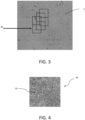
- Surface regions 40 may be arranged side by side (for example, in the case of square surface regions, they may have a checkerboard arrangement, as illustrated in Figure 2 ), and/or they may be partially overlapping each other (in other words, a vertex of one surface region may fall within another surface region, as illustrated in Figure 3 ).
- diffractive grating 30 has grooves that form a pattern having preferentially a random pattern, which, however, is repeated equally in each surface region 40. As visible in Figure 4 , in which the darker parts represent the valleys and the lighter parts the peaks of the grooves of diffractive grating 30, no geometrically defined pattern formed by the grooves can be identified (in this sense, the pattern of the grooves of diffractive grating 30 has a "random" pattern).
- diffractive sensor 1 further comprises a protective layer 4 to protect diffractive grating 30, preferably having a thickness comprised between 1 ⁇ m and 100 ⁇ m.
- the protective layer 4 can be made of a material selected from the group consisting of:
- the protective layer 4 is preferably made by deposition (e.g., under vacuum) of nanoparticles of the above-mentioned materials on the diffractive grating 30.
- the nanoparticles are comprised between 4 and 30 nm in size, still more preferably smaller than or equal to 20 nm, e.g., equal to 8 nm.
- a diffractive phenomenon takes place at the macroscopic level, i.e., visible to the naked eye, similar to that which takes place, for example, at the atomic level following exposure of matter to X-rays, a phenomenon which, however, is not detectable to the naked eye.
- the laser light emitted by laser source 100 can have wavelength ⁇ equal to 532 nm (green light), however the diffraction image can be generated by irradiating sensor 1 with a laser light having any other wavelength in the visible spectrum (indicatively comprised between 390 nm and 700 nm).
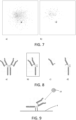
- FIG. 6 An example of a diffraction image that is produced on screen 200 is shown in Figure 6 . It comprises a plurality of dots whose distribution depends on the conformation of the diffractive grating 30 repeated in the surface regions 40. In the figure, a larger dot can be seen, which is the dot aligned with the laser light incident at 90° posterior to the sensor, which passes through it without being diffracted.
- the conformation of the protective layer 4 can affect the brightness of the dots in the diffraction image on the screen 200. For example, it has been observed that employing zinc nanoparticles in the protective layer 4 results in a brighter diffraction image than if gold nanoparticles are used, but the distribution of dots in the diffraction image remains the same. Therefore, the conformation of the diffractive gratings in the surface regions 40 causes sensor 1 to produce a kind of unique fingerprint of sensor 1, that is, precisely the diffraction image. Changing the random pattern conformation of the diffractive grating 30 will also result in a different distribution of dots in the diffraction image.
- diffractive layer 3 is conformed so that the light diffracted by the sensor is polarized.
- the diffraction image can be obtained not only by crossing the sensor by the laser beam from the back side, as described above, but also by reflection of the same, i.e., by pointing a laser beam at an angle to the front surface of the sensor (i.e., on the side opposite to the bottom side, for example, on the side where the protective layer 4 may be arranged). In both cases, a diffraction image having the characteristics said above is obtained.
- diffractive sensor 1 further comprises a receptor layer 5 overlapping and directly in contact with diffractive layer 3, or overlapping and directly in contact with protective layer 4, where present.
- Receptor layer 5 is able to bind selectively to the target analyte to be detected and not to substances of a different nature.
- the target analyte can be contained in a sample, such as a biological solution (e.g., a saliva or blood or urine sample), which can be deposited, for example smeared or rubbed, on receptor layer 5.
- a biological solution e.g., a saliva or blood or urine sample
- diffractive sensor 1 when subjected to a laser light beam as described above, produces a first diffraction image on the screen, visible to the naked eye.
- diffractive sensor 1 when the target analyte is present in the sample, it binds to receptor layer 5, and as a result diffractive sensor 1 produces a second diffraction image different from the first, again visible to the naked eye, and comparable with the diffraction image of the first condition.
- Figure 7 shows a comparison between a diffraction image produced in the case of absent target analyte ( Figure 7a )) and in the case of target analyte present and bound to receptor layer 5 ( Figure 7b )).
- Figure 7a the number and/or distribution and/or light intensity of the dots visible in the diffraction image of the first and second cases are different. Therefore, from the simple visual comparison, which can also be made with the naked eye, of the two diffraction images, it is possible to determine whether the target analyte is present in the sample and has bound to receptor layer 5 of diffractive sensor 1, or not.
- the diffraction image produced by diffractive layer 3 alone is different from the diffraction image produced as a result of the application of receptor layer 5 and is also different from the diffraction image produced in the case where receptor layer 5 binds to the target analyte. Therefore, the sensor comprising diffractive layer 3, with or without protective layer 4, and lacking receptor layer 5, is as such capable of producing a diffraction image which is peculiar to the nanometer diffractive grating, which constitutes a kind of fingerprint of the sensor.
- the diffraction images produced in the presence and absence of the target analyte may also differ from each other in coloration. However, this is a possible secondary effect to the variation in the diffraction image.
- receptor layer 5 following the application of the sample where the possible target analyte presence is to be detected, is washed in an appropriate manner, some possible examples of which will be given below. In this manner, substances or molecules or contaminants, which cannot bind to receptor layer 5 (which is able to selectively bind only to the target analyte), are removed.
- receptor layer 5 in particular its chemical composition, as well as the manner of washing (where applicable), may differ depending on the target analyte being sought.
- receptor layer 5 may include antibodies, proteins, molecules with key-lock action, chelating compounds or other chemical or biological substances that have chelating functions.
- target analytes may include:
- receptor layer 5 of the above-mentioned antibodies enables the latter to selectively detect the presence of these target analytes in the sample that is applied onto receptor layer 5.
- a suitable antibody against a component to be detected by the sensor can also be specifically produced.
- the receptor layer may include the antibody specific for that antigen and nonspecific for antigens other than the target antigen, which is intended to be detected by the sensor 1. It is therefore necessary for the antibody to be firmly bound to the diffractive layer 3 for the detection to be reliable.
- such firm binding can be achieved by binding the antibody to the nanoparticles, preferably metallic, of the protective layer 4.
- Antibodies are modular-structured protein complexes with a common basic structure, but showing variability in specific regions capable of binding to specific antigens.
- antibodies exhibit a Y conformation, with a central stem and two side branches. They comprise four chains covalently linked by -S-S- disulfide bridges and are unable to bind to a metal, such as gold, unless processed in advance.
- One possible pretreatment of the antibody for the purpose of its binding to the protective layer 4, in particular to the metal nanoparticles thereof, involves breaking the -S-S- disulfide bond of a portion of the antibody by reducing it to a reduced -SH disulfide bond, which is instead capable of binding to the metal, in particular forming very strong thiol bonds with the latter.
- receptor layer 5 comprises antibodies or other proteins
- the previously mentioned washing can, for example, be done by the use of PBS (Phosphate Buffered Saline), by immersion and possibly by subsequent centrifugation of the sensor.
- PBS Phosphate Buffered Saline
- receptor layer 5 is able to selectively bind to a plurality of different target analytes, for example in different areas of receptor layer 5, and is configured such that that, depending on the bound target analyte, the diffraction image produced is different.
- receptor layer 5 may include different antibodies positioned in such a way that receptor layer 5 is able to selectively bind to different target antigens.
- the diffraction images produced by the sensor are visible to the naked eye, they can be usefully detected by an automated or partially automated system.
- a possible system for sensing a target analyte in a sample is shown in Figure 5 , which comprises laser source 100, screen 200 (preferably satin), and a vision system capable of acquiring the diffraction image produced by sensor 1, e.g., a video camera 300 pointed at screen 200, connected to a control unit of, for example, a computer 400.
- the latter control unit can possibly perform grayscale conversion of the diffraction image.
- Such a system may be portable, e.g., to perform onsite analysis. In such a case, power supplies and/or batteries may be provided for the above-mentioned equipment.
- a method for sensing a target analyte in a sample comprises the steps of:
- the method comprises a step of converting diffraction images to a grey scale, to remove the coloration that depends on the wavelength of the laser light beam. This step can be carried out, for example, by the control unit.
- the method may further comprise the additional steps of comparing the diffraction image produced by the sensor with a plurality of stored diffraction images (each corresponding to a specific target analyte), and determining the presence of a specific target analyte from the plurality of target analytes detectable by the sensor if the diffraction image produced by the sensor matches the stored diffraction image for that specific target analyte.
- the method comprises an additional step of washing diffractive sensor 1 to remove substances or molecules or contaminants other than the target analyte from receptor layer 5 that might interfere with the final diffraction image, even if only as background noise.
- a washing step can, for example, be carried out by using buffer solutions (e.g., PBS), ionic or non-ionic detergents, or by mild surfactants, according to appropriate procedures and timing.
- the diffractive sensor, system and method according to the present invention can find application in a variety of fields, of which some non-limiting examples are given below:
- overlapping referring to the layers of sensor 1, is not intended to imply necessarily also a direct contact between the mentioned overlapping layers. Such layers may therefore be in direct contact with each other, or, alternatively, they may have one or more intermediate layers arranged between them, without prejudice to their overlapping.
Landscapes
- Health & Medical Sciences (AREA)
- Life Sciences & Earth Sciences (AREA)
- Immunology (AREA)
- Chemical & Material Sciences (AREA)
- Physics & Mathematics (AREA)
- Pathology (AREA)
- General Physics & Mathematics (AREA)
- General Health & Medical Sciences (AREA)
- Biochemistry (AREA)
- Analytical Chemistry (AREA)
- Engineering & Computer Science (AREA)
- Molecular Biology (AREA)
- Urology & Nephrology (AREA)
- Hematology (AREA)
- Biomedical Technology (AREA)
- Medicinal Chemistry (AREA)
- Food Science & Technology (AREA)
- Microbiology (AREA)
- Cell Biology (AREA)
- Biotechnology (AREA)
- Chemical Kinetics & Catalysis (AREA)
- Plasma & Fusion (AREA)
- Investigating Or Analysing Materials By Optical Means (AREA)
Applications Claiming Priority (1)
| Application Number | Priority Date | Filing Date | Title |
|---|---|---|---|
| IT102023000015759A IT202300015759A1 (it) | 2023-07-26 | 2023-07-26 | Sensore diffrattivo per la rilevazione di analiti bersaglio in un campione, e sistema e metodo per la rilevazione di analiti bersaglio in un campione tramite detto sensore diffrattivo |
Publications (1)
| Publication Number | Publication Date |
|---|---|
| EP4498069A1 true EP4498069A1 (fr) | 2025-01-29 |
Family
ID=88290436
Family Applications (1)
| Application Number | Title | Priority Date | Filing Date |
|---|---|---|---|
| EP24164097.8A Pending EP4498069A1 (fr) | 2023-07-26 | 2024-03-18 | Capteur diffractif pour détecter des analytes cibles dans un échantillon, et système et procédé de détection d'analytes cibles dans un échantillon par ledit capteur diffractif |
Country Status (7)
| Country | Link |
|---|---|
| US (1) | US20260016411A1 (fr) |
| EP (1) | EP4498069A1 (fr) |
| JP (1) | JP2025018917A (fr) |
| KR (1) | KR20250017134A (fr) |
| CN (1) | CN119375186A (fr) |
| CA (1) | CA3236431A1 (fr) |
| IT (1) | IT202300015759A1 (fr) |
Citations (4)
| Publication number | Priority date | Publication date | Assignee | Title |
|---|---|---|---|---|
| US4647544A (en) * | 1984-06-25 | 1987-03-03 | Nicoli David F | Immunoassay using optical interference detection |
| US20080240543A1 (en) * | 2007-03-30 | 2008-10-02 | Wolfgang Ernst Gustav Budach | Calibration and normalization method for biosensors |
| US20120034291A1 (en) * | 2009-02-12 | 2012-02-09 | Trustees Of Tufts College | Nanoimprinting of silk fibroin structures for biomedical and biophotonic applications |
| EP3907507A1 (fr) | 2020-05-04 | 2021-11-10 | DG GROUP S.p.A. | Capteur colorimétrique pour la détection de bactéries et/ou de virus |
-
2023
- 2023-07-26 IT IT102023000015759A patent/IT202300015759A1/it unknown
-
2024
- 2024-03-18 EP EP24164097.8A patent/EP4498069A1/fr active Pending
- 2024-04-18 US US18/639,367 patent/US20260016411A1/en active Pending
- 2024-04-25 CA CA3236431A patent/CA3236431A1/en active Pending
- 2024-05-08 JP JP2024075587A patent/JP2025018917A/ja active Pending
- 2024-05-17 KR KR1020240064845A patent/KR20250017134A/ko active Pending
- 2024-05-17 CN CN202410618524.0A patent/CN119375186A/zh active Pending
Patent Citations (4)
| Publication number | Priority date | Publication date | Assignee | Title |
|---|---|---|---|---|
| US4647544A (en) * | 1984-06-25 | 1987-03-03 | Nicoli David F | Immunoassay using optical interference detection |
| US20080240543A1 (en) * | 2007-03-30 | 2008-10-02 | Wolfgang Ernst Gustav Budach | Calibration and normalization method for biosensors |
| US20120034291A1 (en) * | 2009-02-12 | 2012-02-09 | Trustees Of Tufts College | Nanoimprinting of silk fibroin structures for biomedical and biophotonic applications |
| EP3907507A1 (fr) | 2020-05-04 | 2021-11-10 | DG GROUP S.p.A. | Capteur colorimétrique pour la détection de bactéries et/ou de virus |
Non-Patent Citations (18)
| Title |
|---|
| ANKE K. TRILLINGJULES BEEKWILDERAHAN ZUILHOF: "Antibody orientation on biosensor surfaces: a minireview", ANALYST, vol. 138, 2013, pages 1619 |
| ARKADY A. KARYAKIN, GALINA V. PRESNOVA, MAYA YU. RUBTSOVA, ALEXEY M. EGOROV: "Oriented Immobilization of Antibodies onto the Gold Surfaces via Their Native Thiol Groups", ANAL. CHEM., vol. 72, 2000, pages 3805 - 3811 |
| ASTA MAKARAVICIUTE, CAROLYN D. JACKSON, PAUL A.MILLNER, ALMIRA RAMANAVICIENE: "Considerations in producing preferentially reduced half-antibody fragments", JOURNAL OF IMMUNOLOGICAL METHODS, vol. 429, 2016, pages 50 - 56, XP029413067, DOI: 10.1016/j.jim.2016.01.001 |
| HARRY W SCHROEDER JR, LISA CAVACINI: "Structure and Function of Immunoglobulins", ALLERGY CLIN IMMUNOL, vol. 125, February 2010 (2010-02-01), pages S41 - S52, XP055713825, DOI: 10.1016/j.jaci.2009.09.046 |
| HARSH SHARMARAJ MUTHARASAN: "Half Antibody Fragments Improve Biosensor Sensitivity without Loss of Selectivity", ANAL. CHEM., vol. 85, 2013, pages 2472 - 2477 |
| HONGCHENG LIU, KIMBERLY MAY: "Disulfide bond structures of IgG molecules", MABS, vol. 4, no. 1, 2012, pages 17 - 23, XP055696189, DOI: 10.4161/mabs.4.1.18347 |
| JOLLY XAVIER ET AL: "Deterministic aperiodic composite lattice-structured silicon thin films for photon management", ARXIV.ORG, 19 May 2016 (2016-05-19), Ithaca, XP093122692, Retrieved from the Internet <URL:https://arxiv.org/ftp/arxiv/papers/1605/1605.06107.pdf> [retrieved on 20240123], DOI: 10.48550/arxiv.1605.06107 * |
| LU ZHANGYACINE MAZOUZIMICH&LE SALMAINBO LIEDBERGSOUHIR BOUJDAY: "Antibody-Gold Nanoparticle Bioconjugates for Biosensors: Synthesis, Characterization and Selected Applications", BIOSENSORS AND BIOELECTRONICS, vol. 165, 2020, pages 112370, XP093129625, DOI: 10.1016/j.bios.2020.112370 |
| MARTINS EMILIANO R. ET AL: "Deterministic quasi-random nanostructures for photon control", vol. 4, no. 1, 24 October 2013 (2013-10-24), UK, XP093122678, ISSN: 2041-1723, Retrieved from the Internet <URL:https://www.nature.com/articles/ncomms3665> DOI: 10.1038/ncomms3665 * |
| MD. MORSALINE BILLAHCHRISTOPHER S. HODGESHENRY C.W. HAYSP.A. MILLNER: "Directed immobilization of reduced antibody fragments onto a novel SAM on gold for myoglobin impedance immunosensing", BIOELECTROCHEMISTRY, vol. 80, 2010, pages 49 - 54 |
| MONALISA PALSANGHEE LEEDONGHOON KWONJEONGIN HWANGHYEONJEONG LEESEOKYUNG HWANGSANGMIN JEON: "Direct immobilization of antibodies on Zn-doped Fe304 nanoclusters for detection of pathogenic bacteria", ANALYTICA CHIMICA ACTA, vol. 952, 2017, pages 81 - 87, XP029857297, DOI: 10.1016/j.aca.2016.11.041 |
| NICHOLAS G. WELCHJUDITH A. SCOBLEBENJAMIN W. MUIR ET AL.: "Orientation and characterization of immobilized antibodies for improved immunoassays", BIOINTERPHASES, vol. 12, 2017, XP055596739, DOI: 10.1116/1.4978435 |
| NUR MUSTAFAOGLUTANYEL KIZILTEPEBASAR BILGICER: "Site-Specific Conjugation of Antibody on Gold Nanoparticle Surface for One-Step Diagnosis of Prostate Specific Antigen with Dynamic Light Scattering", NANOSCALE, vol. 9, no. 25, 29 June 2017 (2017-06-29), pages 8684 - 8694, XP093129606, DOI: 10.1039/C7NR03096G |
| RAFAEL ANTONIO SALINAS DOMINGUEZMIGUEL ANGEL DOMINGUEZ JIMENEZABDU ORDUNA DIAZ: "Antibody Immobilization in Zinc Oxide Thin Films as an Easy-Handle Strategy for Escherichia coli Detection", ACS OMEGA, vol. 5, 2020, pages 20473 - 20480, XP055949529, DOI: 10.1021/acsomega.0c02583 |
| ROBERTO REVERBERILORENZO REVERBERI: "Factors affecting the antigen-antibody reaction", BLOOD TRANSFUS, vol. 5, 2007, pages 227 - 240, XP055069254, DOI: 10.2450/2007.0047-07 |
| WOOCHANG LEEBYUNG-KEUN OHWON HONG LEEJEONG-WOO CHOI: "Immobilization of antibody fragment for immunosensor application based on surface plasmon resonance", COLLOIDS AND SURFACES B: BIOINTERFACES, vol. 40, 2005, pages 143 - 148 |
| XUEFENG WANG ET AL: "Molecular layer detection on a diffractive optical balance", OPTICS LETTERS, OPTICAL SOCIETY OF AMERICA, US, vol. 37, no. 19, 1 October 2012 (2012-10-01), pages 4098 - 4100, XP001578722, ISSN: 0146-9592, [retrieved on 20120926], DOI: 10.1364/OL.37.004098 * |
| YUANLI SONGHUI CAIZHIJUN TANNESREDIN MUSSAZHENG-JIAN LI: "Mechanistic insights into inter-chain disulfide bond reduction of IgG1 and IgG4 antibodies", APPLIED MICROBIOLOGY AND BIOTECHNOLOGY, vol. 106, 2022, pages 1057 - 1066, XP037683993, DOI: 10.1007/s00253-022-11778-5 |
Also Published As
| Publication number | Publication date |
|---|---|
| KR20250017134A (ko) | 2025-02-04 |
| CA3236431A1 (en) | 2025-06-11 |
| JP2025018917A (ja) | 2025-02-06 |
| US20260016411A1 (en) | 2026-01-15 |
| IT202300015759A1 (it) | 2025-01-26 |
| CN119375186A (zh) | 2025-01-28 |
Similar Documents
| Publication | Publication Date | Title |
|---|---|---|
| Luan et al. | Add-on plasmonic patch as a universal fluorescence enhancer | |
| US7122384B2 (en) | Resonant light scattering microparticle methods | |
| TW412637B (en) | Optical quantification of analytes in membranes | |
| EP3394596B1 (fr) | Détection optique de particules dans un fluide | |
| US20170370836A1 (en) | Mobile/wearable devices incorporating lspr sensors | |
| Liu et al. | Immobilized antibody orientation analysis using secondary ion mass spectrometry and fluorescence imaging of affinity-generated patterns | |
| KR101799163B1 (ko) | 바이오 센서용 광학 표지자, 이를 포함하는 광학 바이오센서 및 상기 바이오 센서용 광학 표지자의 제조방법 | |
| US9995749B2 (en) | Method for detecting a target analyte | |
| TW201538959A (zh) | 用於增強分析靈敏度之數位局域表面電漿子共振(lspr) | |
| WO2016187588A1 (fr) | Nanoparticules plasmoniques et essais reposant sur la lspr | |
| US20100196920A1 (en) | Nanoscopic biomolecular absorption spectroscopy enabled by single nanoparticle plasmon resonance energy transfer | |
| Raez et al. | Spectroscopically encoded microspheres for antigen biosensing | |
| WO1998021571A1 (fr) | Utilisation de biocapteurs pour diagnostiquer des maladies des plantes | |
| US20050163659A1 (en) | Kit for assay development and serial analysis | |
| US9851350B2 (en) | Nanohole sensor chip with reference sections | |
| US20030104390A1 (en) | Use of biosensors to diagnose plant diseases | |
| US20260016411A1 (en) | Diffractive sensor for sensing target analytes in a sample, and system and method for sensing target analytes in a sample by said diffractive sensor | |
| US20070155022A1 (en) | Degenerate binding detection and protein identification using Raman spectroscopy nanoparticle labels | |
| WO2013084074A2 (fr) | Détection spectroscopique de la troponine i et quantification à l'aide de nano-matériaux plasmoniques | |
| BR102024009856A2 (pt) | Sensor difrativo para detectar um analito-alvo, e, sistema e método para detectar um analito-alvo | |
| US20110195516A1 (en) | Wire grid substrate structure and method for manufacturing such a substrate | |
| Lee et al. | Ultra-sensitive detection of tumor necrosis factor-alpha on gold nano-patterned protein chip formed via E-beam nanolithography by total internal reflection fluorescence microscopy | |
| WO2024034561A1 (fr) | Support en phase solide et kit de mesure d'objet cible | |
| JP5205293B2 (ja) | 抗体固定基板、並びに該抗体固定基板の製造方法及び利用 | |
| Drachev et al. | Biomolecule sensing with adaptive plasmonic nanostructures |
Legal Events
| Date | Code | Title | Description |
|---|---|---|---|
| PUAI | Public reference made under article 153(3) epc to a published international application that has entered the european phase |
Free format text: ORIGINAL CODE: 0009012 |
|
| STAA | Information on the status of an ep patent application or granted ep patent |
Free format text: STATUS: REQUEST FOR EXAMINATION WAS MADE |
|
| 17P | Request for examination filed |
Effective date: 20241014 |
|
| AK | Designated contracting states |
Kind code of ref document: A1 Designated state(s): AL AT BE BG CH CY CZ DE DK EE ES FI FR GB GR HR HU IE IS IT LI LT LU LV MC ME MK MT NL NO PL PT RO RS SE SI SK SM TR |
|
| STAA | Information on the status of an ep patent application or granted ep patent |
Free format text: STATUS: EXAMINATION IS IN PROGRESS |
|
| 17Q | First examination report despatched |
Effective date: 20260319 |