EP4498366A1 - Verarbeitung eines audiostereosignals - Google Patents
Verarbeitung eines audiostereosignals Download PDFInfo
- Publication number
- EP4498366A1 EP4498366A1 EP23187751.5A EP23187751A EP4498366A1 EP 4498366 A1 EP4498366 A1 EP 4498366A1 EP 23187751 A EP23187751 A EP 23187751A EP 4498366 A1 EP4498366 A1 EP 4498366A1
- Authority
- EP
- European Patent Office
- Prior art keywords
- signal
- upmix
- channel signals
- iid
- coefficients
- Prior art date
- Legal status (The legal status is an assumption and is not a legal conclusion. Google has not performed a legal analysis and makes no representation as to the accuracy of the status listed.)
- Withdrawn
Links
Images






Classifications
-
- G—PHYSICS
- G10—MUSICAL INSTRUMENTS; ACOUSTICS
- G10L—SPEECH ANALYSIS TECHNIQUES OR SPEECH SYNTHESIS; SPEECH RECOGNITION; SPEECH OR VOICE PROCESSING TECHNIQUES; SPEECH OR AUDIO CODING OR DECODING
- G10L19/00—Speech or audio signals analysis-synthesis techniques for redundancy reduction, e.g. in vocoders; Coding or decoding of speech or audio signals, using source filter models or psychoacoustic analysis
- G10L19/008—Multichannel audio signal coding or decoding using interchannel correlation to reduce redundancy, e.g. joint-stereo, intensity-coding or matrixing
-
- H—ELECTRICITY
- H04—ELECTRIC COMMUNICATION TECHNIQUE
- H04S—STEREOPHONIC SYSTEMS
- H04S1/00—Two-channel systems
- H04S1/007—Two-channel systems in which the audio signals are in digital form
Definitions
- the invention relates to processing, such as encoding/decoding/ downmixing/upmixing/generation of an audio stereo signal, and in particular, but not exclusively, to generation of an audio stereo signal from upmixing of a mono downmix signal using upmix parametric data.
- VR Virtual Reality
- AR Augmented Reality
- equipment is being developed for both rendering the experience as well as for capturing or recording suitable data for such applications.
- relatively low-cost equipment is being developed for allowing gaming consoles to provide a full VR experience. It is expected that this trend will continue and indeed will increase in speed with the market for VR and AR reaching a substantial size within a short time scale.
- a prominent field explores the reproduction and synthesis of realistic and natural spatial audio. The ideal aim is to produce natural audio sources such that the user cannot recognize the difference between a synthetic and an original source.
- a lot of research and development effort has focused on providing efficient and high-quality audio encoding and audio decoding for spatial audio.
- a frequently used spatial audio representation is multichannel audio representations, including stereo representation, and efficient encoding of such multichannel audio based on downmixing multichannel audio signals to downmix channels with fewer channels have been developed.
- One of the main advances in low bit-rate audio coding has been the use of parametric multichannel coding where a downmix signal is generated together with parametric data that can be used to upmix the downmix signal to recreate the multichannel audio signal.
- a multichannel input signal is downmixed to a lower number of channels (e.g. two to one) and multichannel image (stereo) parameters are extracted.
- the downmix signal is encoded using a more traditional audio coder (e.g. a mono audio encoder).
- the bitstream of the downmix is multiplexed with the encoded multichannel image parameter bitstream. This bitstream is then transmitted to the decoder, where the process is inverted.
- the downmix audio signal is decoded, after which the multichannel audio signal is reconstructed guided by the encoded multichannel image upmix parameters.
- the decoding is based on the use of the so-called de-correlation process.
- the de-correlation process generates a decorrelated helper signal from the monaural signal.
- both the monaural signal and the decorrelated helper signal are used to generate the upmixed stereo signal based on the upmix parameters.
- the two signals may be multiplied by a time- and frequency-dependent 2x2 matrix having coefficients determined from the upmix parameters to provide the output stereo signal.
- the approach allows parametric stereo encoding/decoding to be realized with a low (decoder) complexity when combining it with Spectral Band Replication (SBR).
- SBR Spectral Band Replication
- the de-correlation process generates a synthetic helper signal d[n] from the monaural signal m[n].
- both signals m[n] and d[n] are mixed to form the stereo pair l[n], r[n].
- HE-AACv2 see e.g. A. C. den Brinker, J. Breebaart, P. Ekstrand, J. Engdeg ⁇ rd, F. Henn, K. Kjörling, W. Oomen, and H.
- an improved approach would be advantageous.
- an approach allowing increased flexibility, improved adaptability, an improved performance, prevention or mitigation of numerical issues of audio processing including encoding and decoding, increased audio quality, improved audio quality to data rate trade-off, reduced complexity and/or resource usage, reduced computational load, facilitated implementation and/or an improved spatial audio experience would be advantageous.
- the Invention seeks to preferably mitigate, alleviate or eliminate one or more of the above mentioned disadvantages singly or in any combination.
- apparatus for generating an output audio stereo signal comprising: a receiver arranged to receive an audio data signal comprising: a mono audio signal being a downmix of two channel signals of a first audio stereo signal; upmix parameters for the mono audio signal, the set of upmix parameters comprising a first parameter indicative of a level difference between the two channel signals, a second parameter indicative of a correlation between the two channel signals, and a third parameter indicative of a phase difference between the two channel signals; a coefficient generator arranged to generate coefficients for an upmix matrix from the upmix parameters; a generator arranged to generate the output audio stereo signal by applying the upmix matrix to samples of the mono audio signal and an auxiliary mono audio signal; wherein the coefficient generator is arranged to: determine a signal cancellation measure from the upmix parameters, the signal cancellation measure being indicative of a signal cancellation in a summation of the two channel signals; and determine the coefficients for the upmix matrix in dependence on the signal cancellation measure.
- the approach may provide an improved audio experience in many embodiments and applications. For many signals and scenarios, the approach may provide improved generation/ reconstruction of a stereo audio signal with an improved perceived audio quality.
- the approach may provide an efficient implementation and may in many embodiments allow a reduced complexity and/or resource usage.
- the approach may in many scenarios allow a reduced data rate for data representing a multichannel audio signal using a downmix signal.
- the approach may in particular mitigate and compensate for numerical issues, and may typically provide more well-behaved parameter values and/or calculations.
- the processing and parameter determination may prevent that denominators for equations evaluated to determine the upmix coefficients approach zero.
- the approach may prevent or reduce the risk of parameter values (whether final or intermediate) exceeding suitable dynamic ranges, and may specifically prevent or reduce the risk of these parameter values approaching infinity.
- the approach may further achieve such effects while allowing optimum (or improved) determination of upmix parameters for most scenarios. For example, modifications that prevent or mitigate numerical issues may be focused on scenarios where these are likely to occur without having a significant impact on the operation in other scenarios.
- an approach for determining upmix parameters may closely follow the approach of ISO/IEC 14496-3:2005 for many scenarios while specifically preventing or mitigating numerical issues associated with this approach for some scenarios and signals.
- the approach may reduce distortions and artefacts resulting from numerical issues when determining upmix parameter values.
- the apparatus for generating an output audio stereo signal may determine the signal cancellation measure based only on the received upmix parameters, and these may specifically reflect properties of the channel signals of the input stereo signal at the encoder. Accordingly, the same information may be available at both the encoding and decoding side and the same signal cancellation measure may be determined at the encoding and decoding side.
- the upmix parameters may accordingly be determined to match the applied downmix parameters at the encoding side.
- the upmix parameters may be determined such that the upmix matrix closely complements the downmix matrix.
- the upmix matrix may be determined as the inverse of the downmix matrix thereby resulting in the sequence of the downmix matrix multiplication and the upmix matrix multiplication resulting in the unity matrix.
- the samples of the mono audio signal may be frequency domain samples, or may span a particular time and frequency range (specifically subband domain samples).
- the samples of an auxiliary audio signal may be time domain samples, may be frequency domain samples, or may span a particular time and frequency range (specifically subband domain samples).
- the upmix parametric data may comprise data being indicative of relative properties between channel signals of the first stereo audio signal.
- the upmix parameters may comprise data being indicative of differences in properties between channels of the stereo audio signal.
- the upmix parameters comprise data being perceptually relevant for the synthesis of the output stereo audio signal.
- the properties may for example be differences in phase and/or intensity and/or timing and/or correlation.
- the upmix parameters may in some embodiments and scenarios represent abstract properties not directly understandable by a human person/expert (but may typically facilitate a better reconstruction/lower data rate etc).
- the upmix parameters may comprise data including at least one of interchannel intensity differences, interchannel timing differences, interchannel correlations and/or interchannel phase differences for channel signals of the stereo audio signal.
- the upmix parameters may specifically include Interaural Intensity Differences (IIDs), Interaural Level Differences (ILD), Inter-channel Phase Differences (IPDs), Overall Phase Differences (OPDs), Inter-channel Cross Correlations (ICCs), Channel Phase Differences (CPDs) parameters
- IIDs Interaural Intensity Differences
- IPDs Interaural Level Differences
- IPDs Inter-channel Phase Differences
- OPDs Inter-channel Phase Differences
- OPDs Inter-channel Cross Correlations
- CPDs Channel Phase Differences
- the generator may be arranged to generate the output stereo audio signal by applying a matrix multiplication to the mono audio signal and the auxiliary audio signal with the coefficients of the upmix matrix being determined as a function of parameters of the upmix parameters.
- the upmix matrix be time- and frequency-dependent. Equivalently, the upmix matrix may be provided for a time and/or frequency segment, and different matrices may be provided for different time and/or frequency segments.
- the auxiliary signal may be a decorrelated signal generated from the mono audio signal.
- the decorrelated signal may be generated to have the same level and/or frequency distribution as the mono audio signal.
- the auxiliary signal may in some cases be a signal received with the mono audio signal, and may in particular be a side or residual signal for the first audio stereo signal.
- the signal cancellation measure may be indicative of a degree or level of signal cancellation in a summation of the two channel signals.
- the signal cancellation measure may be indicative of a signal level/power/amplitude of a sum signal being a summation of the two channel signals relative to the sum of the signal level/power/ amplitudes of the two channel signals.
- the signal cancellation measure may be indicative of a (degree/level) of signal cancellation in a summation of the two channel signals and/or equivalently may be indicative of a (degree/level) of signal cancellation in a difference/subtraction between the two channel signals (which may be considered a negative signal cancellation for the sum signal).
- the signal cancellation measure may in some embodiments be a normalized signal cancellation measure, and specifically normalized with respect to a level/power/energy of the first stereo signal.
- the signal cancellation measure may in some embodiments be in the range from -1 to +1.
- the sign of the signal cancellation measure may indicate whether signal cancellation occurs in a summation of the channel signals and/or in a difference/ subtraction between the channel signals.
- the coefficient processor is arranged to adapt the upmix coefficients to deviate from coefficients for the mono audio signal being a sum signal of the channel signals for the signal cancellation measure meeting a first signal cancellation requirement.
- This may provide a particularly advantageous implementation and/or performance, and may in particular in many scenario prevent or mitigate numerical issues, artefacts, and/or signal distortions.
- the coefficient processor is arranged to increase a deviation of upmix coefficients from coefficients for the mono audio signal being a sum signal of the channel signals for the signal cancellation measure being indicative of an increasing signal cancellation in the sum signal of the channel signals.
- This may provide a particularly advantageous implementation and/or performance, and may in particular in many scenario prevent or mitigate numerical issues, artefacts, and/or signal distortions.
- the coefficient processor is arranged to increase a deviation of upmix coefficients from coefficients for the mono audio signal being a sum signal of the channel signals for the signal cancellation measure being indicative of an increasing signal cancellation in a difference signal of the channel signals.
- This may provide a particularly advantageous implementation and/or performance, and may in particular in many scenario prevent or mitigate numerical issues, artefacts, and/or signal distortions.
- This may provide a particularly advantageous implementation and/or performance, and may in particular in many scenario prevent or mitigate numerical issues, artefacts, and/or signal distortions.
- This may provide a particularly advantageous implementation and/or performance, and may in particular in many scenario prevent or mitigate numerical issues, artefacts, and/or signal distortions.
- the coefficient processor is arranged to generate a first intermediate parameter indicative of a prediction of a difference signal for the channel signals from the mono audio signal, and to generate the upmix coefficients in response to the first intermediate parameter, the first intermediate parameter being dependent on the signal cancellation measure.
- This may provide a particularly advantageous implementation and/or performance, and may in particular in many scenario prevent or mitigate numerical issues, artefacts, and/or signal distortions.
- the coefficient processor (107) is arranged to generate a second intermediate parameter indicative of a residual signal for the prediction, and to generate the upmix coefficients in response to the intermediate parameter, the second intermediate parameter being dependent on the signal cancellation measure.
- This may provide a particularly advantageous implementation and/or performance, and may in particular in many scenario prevent or mitigate numerical issues, artefacts, and/or signal distortions.
- the coefficient processor (107) is arranged to generate the upmix matrix as: 1 2 c ⁇ 1 g 11 ⁇ g 22 ⁇ g 12 ⁇ g 21 g 22 ⁇ g 21 + ⁇ g 11 ⁇ g 12 ⁇ g 11 ⁇ g 12 g 22 + g 21 ⁇ ⁇ g 11 + g 12 ⁇ ⁇ g 11 + g 12
- c is a gain parameter and ⁇ and ⁇ are parameters dependent on the upmix parameters and the signal cancellation measure
- the parameters g 1,1 , g 1,2, g 2,1 , and g 2,2 are dependent on the signal cancellation measure.
- the coefficient processor (107) is arranged to generate the upmix matrix as: 1 2 c ⁇ 1 g 11 ⁇ g 22 ⁇ g 12 ⁇ g 21 g 22 ⁇ g 21 + ⁇ g 11 ⁇ g 12 ⁇ g 11 ⁇ g 12 g 22 + g 21 ⁇ ⁇ g 11 + g 12 ⁇ ⁇ g 11 + g 12 ⁇ ⁇ g 11 + g 12
- IID is an Interaural Intensity Differences upmix parameter
- ICC is an Interchannel Cross Correlations upmix parameter
- IPD is an Inter-channel Phase Difference upmix parameter; and wherein g 11 g 12 g 21 g 22 is a dependent on the signal cancellation measure.
- This may provide a particularly advantageous implementation and/or performance, and may in particular in many scenario prevent or mitigate numerical issues, artefacts, and/or signal distortions.
- g 11 g 12 g 21 g 22 1 ⁇ z 2 z ⁇ z 1 ⁇ z 2 where z is dependent on the signal cancellation measure.
- This may provide a particularly advantageous implementation and/or performance, and may in particular in many scenario prevent or mitigate numerical issues, artefacts, and/or signal distortions.
- g 11 g 12 g 21 g 22 1 ⁇ 1 ⁇ 2 1 where ⁇ 1 and ⁇ 2 are dependent on the signal cancellation measure.
- This may provide a particularly advantageous implementation and/or performance, and may in particular in many scenario prevent or mitigate numerical issues, artefacts, and/or signal distortions.
- an apparatus for generating an audio data signal comprising: a receiver arranged to receive an audio stereo signal comprising two channel signals; a downmixer arranged to generate a mono audio signal as a combination of the two channel signals in dependence on a set of downmix coefficients; a parameter generator arranged to generate a set of upmix parameters comprising a first parameter indicative of a level difference between the two channel signals, a second parameter indicative of a correlation between the two channel signals, and a third parameter indicative of a phase difference between the two channel signals; a downmix coefficient processor arranged to generate the set of downmix coefficients in dependence on the set of upmix parameters; a data signal generator arranged to generate the audio signal to include the mono audio signal and the set of upmix parameters; a signal cancellation estimator which is arranged to determine a signal cancellation measure from the set of upmix parameters, the signal cancellation measure being indicative of a signal cancellation in a summation of the two channel signals; and wherein the downmix coefficient processor is arranged
- a method of generating an output audio stereo signal comprising: receiving an audio data signal comprising: a mono audio signal being a downmix of two channel signals of a first audio stereo signal; upmix parameters for the mono audio signal, the set of upmix parameters comprising a first parameter indicative of a level difference between the two channel signals, a second parameter indicative of a correlation between the two channel signals, and a third parameter indicative of a phase difference between the two channel signals; generating coefficients for an upmix matrix from the upmix parameters; generating the output audio stereo signal by applying the upmix matrix to samples of the mono audio signal and an auxiliary mono audio signal; wherein generating the coefficients comprises: determining a signal cancellation measure from the upmix parameters, the signal cancellation measure being indicative of a signal cancellation in a summation of the two channel signals; and determining the coefficients for the upmix matrix in dependence on the signal cancellation measure.
- a method of generating an audio data signal comprising: receiving an audio stereo signal comprising two channel signals; generating a mono audio signal as a combination of the two channel signals in dependence on a set of downmix coefficients; generating a set of upmix parameters comprising a first parameter indicative of a level difference between the two channel signals, a second parameter indicative of a correlation between the two channel signals, and a third parameter indicative of a phase difference between the two channel signals; generating the set of downmix coefficients in dependence on the set of upmix parameters; generating the audio signal to include the mono audio signal and the set of upmix parameters; determining a signal cancellation measure from the set of upmix parameters, the signal cancellation measure being indicative of a signal cancellation in a summation of the two channel signals; and wherein generating the set of downmix coefficients is in dependence on the signal cancellation measure.
- FIG. 1 and 2 illustrate elements of audio apparatuses in accordance with some embodiments of the invention.
- the audio apparatus of FIG. 1 may typically be considered to perform a decoding and upmix function/ operation and will accordingly also for brevity be referred to as a decoder.
- the audio apparatus of FIG. 2 may typically be considered to perform an encoding and downmix function/ operation and will accordingly also for brevity be referred to as an encoder.
- the audio apparatus of FIG. 1 comprises a receiver 101 which is arranged to receive a data signal/ bitstream comprising a downmix mono audio signal that is a downmix of a stereo audio signal which comprises two channel signals, typically corresponding to a left channel signal and a right channel signal.
- the stereo signal is in the specific example one that has been provided to the encoder of FIG. 2 and downmixed to the mono audio signal by this encoder.
- the received data signal includes upmix parametric data for upmixing the downmix audio signal.
- the upmix parametric data may specifically be a set of parameters that indicate relationships between the signals of the two different audio channels of the stereo audio signal, i.e. of the channel signals that are combined into the downmix mono audio signal.
- the upmix parameters may be indicative of time differences, phase differences, level/intensity differences and/or a measure of similarity, such as correlation, between the two channel signals (i.e. between the input left and right signal).
- the upmix parameters are provided on a per time and per frequency basis (time frequency tiles). For example, new parameters may periodically be provided for a set of subbands.
- Parameters may specifically include Interaural Intensity Differences (IIDs), Interaural Level Differences (ILD), Inter-channel Phase Differences (IPDs), Overall Phase Differences (OPDs), Inter-channel Cross Correlations (ICCs), Channel Phase Differences (CPDs) parameters as known from Parametric Stereo encoding (as well as from higher channel encodings).
- IIDs Interaural Intensity Differences
- IPDs Interaural Level Differences
- IPDs Inter-channel Phase Differences
- OPDs Overall Phase Differences
- OPDs Inter-channel Cross Correlations
- CPDs Channel Phase Differences
- the mono audio signal is an encoded audio signal that has been encoded in accordance with a suitable mono signal encoding standard or approach, and the receiver 101 may decode the received encoded mono audio signal using a decoding approach corresponding to the encoding approach of the encoder.
- the receiver 101 is coupled to a generator 103 which generates an output stereo audio signal corresponding to the stereo audio signal from the downmix signal.
- the generator 103 is arranged to generate the output stereo audio signal from the mono audio signal and an auxiliary audio signal in dependence on the parametric upmix data.
- the generator may specifically generate the output stereo audio signal by applying a 2x2 matrix multiplication to the samples of the mono audio signal and the auxiliary audio signal.
- the coefficients of the 2x2 matrix also known as an upmix matrix, are determined from the upmix parameters of the upmix parametric data, typically on a time and frequency band basis.
- the upmixing includes generating an auxiliary audio signal in the form of a decorrelated signal of the mono audio signal. It has been found that by generating a decorrelated signal and mixing this with the mono audio signal, an improved quality of the upmix signal is perceived and therefore decoders have been developed to exploit this.
- the decorrelated signal is typically generated by a decorrelator 105, such as an all-phase filter that is applied to the mono audio signal.
- the auxiliary signal may be a signal received together with the mono audio signal, in specifically may be a signal generated from a received residual or side signal generated at the encoder side and transmitted to the decoder side.
- a decorrelator 105 is used to generate a decorrelated signal d as a decorrelated version of the mono audio signal (typically with the same energy/ level and spectral shape as the mono audio signal).
- the decoder of FIG. 1 further comprises a coefficient processor 107 which is arranged to generate the coefficients for the upmix matrix H from the received upmix parameters as will be described in more detail later.
- the coefficients for the upmix matrix H may be generated from received IID, ICC, IPD parameters.
- the coefficients of the upmix matrix may in some examples be generated for each sample instant of the signals but is typically generated at a much lower update rate. In such cases, the same coefficients may for example be used for a group/block/segment of samples, or the coefficient processor 107 may for example be arranged to interpolate between determined values.
- the upmix matrix H may be defined at discrete time points sampled at a lower rate than that which the samples are determined and temporal interpolation may be used to provide more appropriate time varying coefficients.
- FIG. 2 illustrates an example of an apparatus, henceforth also referred to as an encoder, which may generate the audio data signal that may be received by the decoder of FIG. 1 .
- the encoder comprises a receiver 201 which receives an input stereo audio signal that is to be encoded and transmitted.
- the stereo audio signal includes two channel signals l,r that are fed to a downmixer 203 which is arranged to generate a mono audio signal comprising the majority of the signal energy of the channel signals l,r as well as typically a residual signal or side signal s .
- the encoder further comprises an upmix parameter generator 205 which is arranged to determine upmix parameters characterizing properties of the input channel signals l,r.
- the upmix parameter generator 205 is arranged to generate IID, ICC, IPD parameters.
- the encoder further comprises a downmix coefficient processor 207 which is arranged to determine the downmix coefficients for the downmix based on the upmix parameters (which accordingly may also be considered to be downmix parameters).
- the upmix/downmix parameters may specifically reflect how the downmix is performed in the encoder and how the upmix should be performed in the decoder.
- the encoder further comprises a data signal generator 209 which is arranged to receive at least the downmix mono signal m and the upmix parameters and to generate the data signal to include these.
- the data signal generator 209 may specifically be arranged to generate suitable data representing these signals and parameters and may thus include suitable encoder functions, bitstream formatting functions, etc. as will be well known to the skilled person.
- the data signal generator 209 is arranged to generate the data signal to not include the residual/side signal s but in some embodiments this signal may also be encoded and included in the data signal. In such cases, the residual/side signal s is typically encoded at a much lower data rate than the mono audio signal m reflecting the reduced energy and reduced perceptual impact on the stereo signal generated at the decoder side.
- MPEG Moving Pictures Expert Group
- the decorrelated signal d is derived by applying a reverberant type processing on the signal m.
- FIG. 3 shows the parameter flowchart. From the IID, ICC and IPD parameters the intermediate parameters c, ⁇ and ⁇ are calculated. These are then used to calculate the entries of the H matrix.
- the parameter value ⁇ is a complex value that is determined to provide the optimal predication of the difference signal from the sum signal, and thus specifically of the difference signal from the mono audio signal m that is generated (noting that the remaining matrix multiplication retain the m signal as a direct sum signal l + r ).
- the parameter value ⁇ is a gain parameter that adapts the level of the decorrelated signal d' to have a signal power corresponding to that of the mid/sum signal m. It should be noted that the residual signal is uncorrelated from the mid (mono) signal (due to the prediction using the parameter ⁇ ).
- the last parameter c is a coefficient which is used to maintain signal power in the downmix and specifically it is set to ensure that c ⁇ ( l + r ) has approximately the same power as the sum of the signal powers of left and right channel signals.
- the value is clipped/limited to a value of c max in order to maintain a practical range of values.
- the standardized approach for parametric stereo encoding and decoding provides for a very advantageous operation, and in particular provides a high audio quality to data rate ratio/trade-off.
- the Inventor has realized that in some situations, and in particular for some signals, the standardized approach leads to less than optimal encoding, and indeed may lead to significant degradation and distortion in some particular situations.
- the Inventor has furthermore realized that such effects and scenarios may be mitigated or reduced by performing specific modified operations.
- the Inventor has in particular realized that issues may occur when the channel signals of the input stereo audio signal are identical or are identical except for being 180° out of phase.
- the intermediate parameters may approach values that result in numerical problems and issues in the processing resulting in degradations and distortions to the resulting decoded stereo audio signal.
- values of the encoding and/or decoding may approach infinite values that cannot be appropriately represented.
- the downmix signal may start to include (time-frequency) gaps in which the sum signal may essentially have no energy (i.e. a zero signal), and this may make it extremely difficult to reconstruct a stereo signal.
- the coefficient generator 107 is arranged to determine intermediate parameters from the upmix parameters and then to determine the upmix matrix coefficients from the intermediate parameters.
- the intermediate parameters may correspond closely to those applied in ISO/IEC 23003-3:2020 but may be modified in particular for some specific inter-signal properties.
- the coefficient processor 107 is arranged to determine a signal cancellation measure from the upmix parameters where the signal cancellation measure is indicative of a signal cancellation in a summation of the two channel signals of the original input stereo audio signal to the encoder.
- the properties of these channel signals of the original input stereo audio signal are represented by the upmix parameters.
- the upmix parameters such as specifically the IID, IPD, and ICC, are dependent on the input channel signals, and in particular on the relative differences between the input channel signals.
- the upmix parameters are dependent only on properties of the channel signals, and specifically the relative properties of the channel signals.
- the coefficient processor 107 may on the basis of the information provided by the upmix parameters indicating relative properties of the channel signals proceed to determine how much signal cancellation would result when adding the channel signals together.
- the signal cancellation measure may be indicative of the energy/power/amplitude (square root of power)/ signal level for the sum signal 1+r of the channel signals relative to the sum/combination of the energy/power/amplitude (square root of power)/ signal level of the two individual channel signals 1 and r.
- the signal cancellation measure may be indicative of a sum signal energy measure determined from the upmix parameters where the sum signal energy measure may be indicative of an energy level of a sum signal that is a summation of the channel signals relative to combination/summation of an energy level of the individual channel signals.
- a signal cancellation measure may be generated to reflect a difference between the received upmix parameters and the upmix parameters corresponding to the extreme scenarios of in-phase or out-of-phase signal cancellation.
- the signal cancellation measure may be determined based on a comparison of the received upmix parameters relative to the upmix parameters that correspond to the maximum cancellation and/or the minimum (the inverse) cancellation (i.e. amplification) of the sum signal.
- the signal cancellation measure may be determined as a function of the upmix parameters.
- This value will attain the value of 1 and -1 respectively in the extreme situations of complete signal cancellation and provide increasingly different values for other values of the upmix parameters. It may thus provide a suitable indication of how close the stereo signal is to respectively a scenario where the channel signals cancel out in the sum signal 1+r or in the difference signal 1-r (corresponding to a maximum negative signal cancellation for the sum signal).
- This signal cancellation measure has some properties that are particular advantageous in many scenarios and embodiments. Since 0 ⁇ ICC ⁇ 1 , ⁇ 1 ⁇ cos IPD ⁇ 1 , and IID + 1 IID ⁇ 2 , it follows that ⁇ 1 ⁇ R ⁇ 1 .
- the ratio of these two factors may provide a particularly advantageous signal cancellation measure for indicating how close the current scenario is to the problematic in-phase and out-of-phase scenarios, and in particular how close the current scenario is to a full signal cancellation in either the sum of the channel signals or the difference of the channel signals.
- the specific signal cancellation measure described above accordingly provides a particularly advantageous measure in many embodiments.
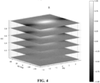
- FIG. 4 illustrates how the R value above varies with the upmix parameters. As can be seen, it provides a good indication of when signal cancellation may occur.
- the coefficient processor 107 is arranged to determine the coefficients for the upmix matrix in dependence on the signal cancellation measure.
- the coefficient processor 107 may be arranged to modify operation such that the operation is adapted to compensate/modify the operation in scenarios where signal cancellation may occur in a sum signal and/or a difference signal.
- the coefficient processor 107 may specifically be arranged to modify the determination of the coefficients for situations approaching signal cancellation such that the numerical problems are mitigated, and in particular such that the determination, and in particular intermediate parameters, do not approach problematic values, and specifically that they do not approach infinity.
- the coefficient processor 107 may specifically be arranged to adapt the operation/ equations for determining the coefficients such that the required dynamic ranges of intermediate calculations and intermediate parameters may be more constrained thereby allowing practical applications and reducing the numerical challenges and issues.
- the coefficient processor 107 is arranged to adapt the upmix coefficients ( H 11 , H 21 ) for the mono audio signal to deviate from coefficients for the mono audio signal being a sum signal of the channel signals for the signal cancellation measure meeting a first signal cancellation requirement. Indeed, in the case where the mono audio signal is a sum signal, the optimum coefficients for determining the channel signals of the output stereo signals will be given as a function of the upmix parameters. However, the coefficient processor 107 may be arranged to generate the coefficients such that they differ and deviate from such values in case of the signal cancellation measure meeting a requirement. Specifically, the coefficient processor 107 may be arranged to differ from these values if the signal cancellation measure is indicative of a signal cancellation in the sum and/or difference signal above a given threshold.
- the cancellation requirement may require the signal cancellation measure to be indicative of a signal cancellation of the sum signal above a threshold.
- the coefficient processor 107 in the approach of FIG. 1 proceeds to, for at least some values, deviate from the values that are optimum for the mono audio signal being a sum signal.
- the degree of deviation from the coefficients for a mono signal being a sum signal of the channel signals may depend on the signal cancellation measure, and may specifically be a monotonically increasing function of a degree of signal cancellation in a sum of the channel signals.
- the determination of the coefficients is modified to increasingly deviate from the coefficients that would be determined for the mono audio signal being a sum signal.
- the upmix coefficients determined for a mono audio signal being a direct sum signal may become increasingly large and may indeed approach infinity or be non-defined.
- the signal cancellation measure is determined and used to control the coefficient determination such that this is mitigated and prevented, and thus coefficients are determined which deviate from the potentially ideal coefficients for a sum signal, but which have reduced numerical issues.
- the coefficient processor 107 is arranged to increase a deviation of the upmix coefficients for the mono audio signal from the coefficient values for the mono audio signal being a sum signal of the channel signals for the signal cancellation measure being indicative of an increasing signal cancellation in a sum signal for a sum signal of the channel signals.
- the deviation from reference coefficient values increases for the signal cancellation measure being indicative of an increasing signal cancellation in the sum of the channel signals where the reference coefficient values are (optimum) coefficients for the mono audio signal being a sum signal.
- the coefficient processor 107 is arranged to increase a deviation of upmix coefficients for the mono audio signal from the coefficient values for the mono audio signal being a difference/subtraction signal of the channel signals for the signal cancellation measure being indicative of an increasing signal cancellation in a difference/ subtraction signal for a difference/subtraction signal of the channel signals.
- the deviation from reference coefficient values increases for the signal cancellation measure being indicative of an increasing signal cancellation in the difference between of the channel signals where the reference coefficient values are (optimum) coefficients for the mono audio signal being a sum signal.
- the coefficient processor 107 is arranged to determine the upmix coefficients for the mono audio signal to be coefficients for the mono audio signal being a sum signal of the channel signals for the signal cancellation measure meeting a second signal cancellation requirement.
- the coefficient processor 107 may generate the coefficients based on the mono audio signal being a sum signal, and indeed in some embodiments, the coefficient processor 107 may in this scenario determine the coefficients substantially as defined in e.g. ISO/IEC 23003-3:2020.
- the coefficient processor 107 may be arranged to generate the upmix coefficients as (optimum) coefficients for the mono audio signal being a sum signal of the input channel signals when the signal cancellation measure is indictive of a low signal cancellation in the sum and/or difference signal and to generate the upmix coefficients to deviate from upmix coefficients that are optimum for the mono audio signal being a sum signal when the signal cancellation measure is indicative of high signal cancellation.
- the above described approach may be applied to all the coefficients of the upmix matrix, and indeed all of the coefficients may be determined to deviate from the coefficients that would apply to a sum signal for at least some values of the signal cancellation measure.
- the approach may only be applied to a subset of one, two, or three of the coefficients.
- the approach may only be applied to the coefficients for the mono audio signal or for the coefficients for the auxiliary audio signal.
- a similar approach may be used for the upmix coefficients ( H 12 , H 22 ) for the auxiliary signal but in this case with the deviation being introduced for signal cancellation in the difference signal of the channel signals, corresponding to a maximum negative cancellation in the sum signal (i.e. maximum level increase in the sum signal).
- the coefficients for the mono audio signal being a sum signal of the channel signals may specifically be optimum coefficients for generating the output stereo audio signal from a mono audio signal being a sum signal of the input channel signals and an auxiliary signal, which specifically may be a decorrelated version of the mono audio signal.
- the values IID, ICC, and IPD may specifically be determined in accordance with ISO/IEC 23003-3:2020.
- the summation over i could refer to a group of frequency domain coefficients, or could refer to a summation both over a window in time and frequency in case of (complex-valued) subband representations.
- the upmix parameters IID, ICC, and IPD depend only on the input signals and are not modified based on the downmix, signal cancellation, or indeed any part of the processing or encoding of the input stereo signal. This is highly beneficial in many scenarios and embodiments. Indeed, a particular advantage is that the perceptual sensitivities of the parameters are well known and understood.
- the coefficient processor 107 may be arranged to determine coefficients that deviate from the optimum coefficients that would be applied to a mono audio signal being a sum signal of the channel signals.
- the deviation is dependent on the signal cancellation measure and thus may specifically be targeted at the specific situations where signal cancellation will occur in the sum signal.
- the approach may accordingly deviate from the theoretical or optimum processing, it may in practice mitigate and often remove numerical issues and the difficulties and degradations associated therewith. This may provide improved audio quality, improved robustness, and/or reduced degradation/ artefacts in many scenarios.
- this approach may be used with an encoder that fixedly generates the mono audio signal as a sum signal, and thus a suboptimal upmixing may be performed.
- mitigating and reducing numerical problems and issues may often substantially outweigh the effects of modifying the upmix coefficients, especially as this can be limited to specific scenarios in which the numerical issues would be highly detrimental and cause substantial distortion.
- the encoder may be arranged to also determine the downmix coefficients to reflect the differences in the upmix coefficients, i.e. the deviation of the upmix coefficients may be complemented by a corresponding operation at the encoder such that the generated mono audio signal (and possibly a residual signal) is modified in scenarios where the signal cancellation may exceed a given level.
- the downmixing at the encoder and the upmixing at the decoder may be complementary and both may be dependent on the signal cancellation in a sum/difference of the two input channel signals.
- the signal may be modified to not be determined simply as the sum signal.
- the decoder may be arranged to complement and compensate for this changed operation.
- the upmixing at the decoder side may be modified correspondingly.
- a similar approach may be used for signal cancellation in the difference signal.
- the generation of the difference signal may be modified to include an element of the sum signal thereby preventing that the signal level falls below a given value.
- the encoder may modify the downmixing depending on the signal cancellation in a sum and/or difference signal for the two channel signals, and in particular may modify the downmixing coefficients of the downmixing matrix generating the mono audio signal, and optionally a side or auxiliary signal.
- the encoder of FIG. 2 accordingly also includes a signal cancellation estimator 211 which receives the upmix parameters determined by the upmix parameter generator 205.
- the signal cancellation estimator 211 is then arranged to determine a signal cancellation measure from the set of upmix parameters where the signal cancellation measure is again indicative of a signal cancellation in a summation of the two channel signals of the input stereo signal.
- the signal cancellation estimator 211 may specifically be arranged to determine the signal cancellation measure using the same algorithm, formulas, and approach as the coefficient processor 107 of the decoder. Thus, the description provided on the generation of the signal cancellation measure by the coefficient processor 107 apply equally (mutatis mutandis) to the determination of the signal cancellation measure signal generated by the cancellation estimator 211.
- the signal cancellation estimator 211 may accordingly generate a signal cancellation measure which is identical to that generated by the coefficient processor 107 of the decoder.
- the encoder and decoder may accordingly in many embodiments generate the same signal cancellation measure, and thus may be arranged to use coordinated and complementary approaches for generating the coefficients for respectively the downmix matrix of the encoder and the upmix matrix of the encoder. Indeed, in many embodiments, the coefficients may be generated such that the two matrices are the inverse of each other thereby resulting in an overall downmix and upmix operation that restores the original input stereo signal.
- the described approaches may typically provide a compatibility with existing Standards and Technical Specifications, such as the ISO/IEC 23003-3:2020 specification.
- the parameters ⁇ , ⁇ , and c are parameters determined from the upmix parameters to provide specific functions/ compensate for specific properties of the channel signals. It should be noted that the signal d' is typically not explicitly calculated in the encoder but the parameters ⁇ , ⁇ , and c involved in generating this signal are determined.
- the parameter value ⁇ is determined to be generate a prediction of the difference signal 1-r from the sum signal l+r. It is thus a parameter that indicates a prediction of the difference signal from the sum signal.
- the parameter ⁇ is a gain parameter which adapts the gain of the decorrelated signal d' to match that of the mono audio signal m.
- the parameter ⁇ is determined to indicate the relative difference (and specifically the ratio) between energies/levels/ amplitudes of the residual signal resulting from the prediction and the generated mono audio signal.
- the parameter is determined to adjust the overall gain/energy of the mono audio signal.
- the gains/coefficients g 11 , g 12 , g 21 and g 22 of the gain matrix may then be determined to compensate for signal cancellation in the sum signal and difference signal respectively. Accordingly, the gains/coefficients may be determined based on a signal cancellation measure that is determined in the encoder and which reflects the signal cancellation in the sum and/or difference signals for the input channel signals.
- the gain coefficients may be determined as a function of the upmix parameters/ parametric stereo parameters. These values are only dependent on the input signals and represent properties of the input stereo audio signal. In particular, the upmix parameters are not dependent on the output mono audio signal but can be determined directly from the input stereo audio signal without any consideration of any other signals.
- the encoder may be arranged to determine the upmix parameters ICC, IID, and IPD from the input stereo audio signal, i.e. from the input channel signals. It may then determine the gains/coefficients of the gain matrix from the upmix parameters. Specifically, the gains/coefficients may be determined such that for the input channel signals being substantially identical but out of phase, corresponding to a high signal cancellation for the sum signal, the gain matrix multiplication results in some of the difference signal being added to the mid signal, i.e. the gain matrix multiplication may results in the sum signal being modified to include some of the difference signal thereby preventing a full signal cancellation in the sum signal.
- the gains/coefficients may be determined such that for the input channel signals being substantially identical and in phase, corresponding to a high signal cancellation for the difference signal, the gain matrix multiplication results in some of the sum signal being added to the difference signal, i.e. the gain matrix multiplication may results in the difference signal being modified to include some of the sum signal thereby preventing a full signal cancellation for the difference signal.
- the gains may (also) be determined as a function of the upmix/ parametric stereo parameters thereby allowing them to be determined equally at the encoder and decoder side.
- the matrix can be condensed into a single matrix: c g 11 + g 12 g 11 ⁇ g 12 ⁇ ⁇ g 11 + g 12 + g 21 + g 22 ⁇ ⁇ ⁇ g 11 ⁇ g 12 + g 21 ⁇ g 22 ⁇ ,
- the coefficient processor 107 may then for a scenario in which significant signal cancellation occurs in the difference signal 1-r (IID ⁇ 1, ICC ⁇ 1, IPD ⁇ 0), determine the gain matrix to have the following properties: g 11 ⁇ 1 g 12 ⁇ 0 g 21 ⁇ 0 g 22 ⁇ 1
- the downmix operation is modified to such that some of the sum signal is mixed into the different signal.
- the coefficient processor 107 may then for a scenario in which significant signal cancellation occurs in the difference signal 1-r (IID ⁇ 1, ICC ⁇ 1, IPD ⁇ ), determine the gain matrix to have the following properties: g 11 ⁇ 1 g 12 ⁇ 0 g 21 ⁇ 0 g 22 ⁇ 1
- the downmix operation is modified to such that some of the difference signal is mixed into the sum signal to generate the mono audio signal.
- the encoder may for highly correlated out-of-phase signals modify the downmix coefficients such that some of the difference signal 'leaks' (is added) to the sum signal. This may ensure that the situation where the sum signal/ mono audio signal diminishes is prevented.
- the downmixing may remain close to the approach of e.g. the ISO/IEC 23003-3:2020 specification.
- the parameter c is a gain parameter/ coefficient that in many embodiments may be set to a suitable value by the decoder, and specifically it may be a design parameter that can be set in accordance with any suitable algorithm or criterion.
- the values of the gain matrix G g 11 g 12 g 21 g 22 are dependent on the signal cancellation measure but it will be appreciated that the exact dependency will depend on the specific preferences and requirements of the individual embodiment and application.
- FIG. 5 and 6 illustrate an example of the absolute difference between the intermediate parameter ⁇ determined from the equations above and from the equations of ISO/IEC 14496-3:2005.
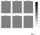
- FIG. 7 and 8 illustrate an example of the absolute difference between the intermediate parameter ⁇ determined from the equations above and from the equations of ISO/IEC 14496-3:2005.
- the approach allows for the deviation from the parameter values of ISO/IEC 14496-3:2005 to mainly be restricted to scenarios where the upmix parameters indicate that substantial signal cancellation occurs.
- the coefficient processor 107 may accordingly proceed to generate an intermediate parameter ⁇ in dependence on the upmix parameters and the signal cancellation measure (as the gains g are dependent on the signal cancellation measure).
- the intermediate parameter ⁇ is indicative of the prediction of a difference signal of the channel signals from the mono audio signal where the difference signal may specifically be a subtraction signal 1-r (or r-1).
- the coefficient processor 107 may then generate the coefficients of the upmix matrix in dependence on the first intermediate parameter.
- the coefficient processor 107 may be arranged to generate a second intermediate parameter ⁇ which is indicative of a residual signal that results after the prediction based on the first intermediate parameter ⁇ .
- the second intermediate parameter ⁇ is determined in dependence on the upmix parameters and the signal cancellation measure.
- the coefficient processor 107 may then proceed to generate the upmix matrix coefficients in dependence on these intermediate parameters.
- ⁇ and ⁇ parameters may again be determined using the equations above.
- the normalizing factor of the determinant can be included in/ compensated for by the gain factor c and accordingly it can be seen that the approaches of the examples are equivalent.
- the audio apparatus(es) may specifically be implemented in one or more suitably programmed processors.
- the artificial neural networks may be implemented in one more such suitably programmed processors.
- the different functional blocks, and in particular the artificial neural networks, may be implemented in separate processors and/or may e.g. be implemented in the same processor.
- An example of a suitable processor is provided in the following.
- FIG. 9 is a block diagram illustrating an example processor 900 according to embodiments of the disclosure.
- Processor 900 may be used to implement one or more processors implementing an apparatus as previously described or elements thereof (including in particular one more artificial neural network).
- Processor 900 may be any suitable processor type including, but not limited to, a microprocessor, a microcontroller, a Digital Signal Processor (DSP), a Field ProGrammable Array (FPGA) where the FPGA has been programmed to form a processor, a Graphical Processing Unit (GPU), an Application Specific Integrated Circuit (ASIC) where the ASIC has been designed to form a processor, or a combination thereof.
- DSP Digital Signal Processor
- FPGA Field ProGrammable Array
- GPU Graphical Processing Unit
- ASIC Application Specific Integrated Circuit
- the processor 900 may include one or more cores 902.
- the core 902 may include one or more Arithmetic Logic Units (ALU) 904.
- ALU Arithmetic Logic Units
- the core 902 may include a Floating Point Logic Unit (FPLU) 906 and/or a Digital Signal Processing Unit (DSPU) 908 in addition to or instead of the ALU 904.
- FPLU Floating Point Logic Unit
- DSPU Digital Signal Processing Unit
- the processor 900 may include one or more registers 312 communicatively coupled to the core 902.
- the registers 912 may be implemented using dedicated logic gate circuits (e.g., flip-flops) and/or any memory technology. In some embodiments the registers 912 may be implemented using static memory.
- the register may provide data, instructions and addresses to the core 902.
- processor 900 may include one or more levels of cache memory 910 communicatively coupled to the core 902.
- the cache memory 910 may provide computer-readable instructions to the core 902 for execution.
- the cache memory 910 may provide data for processing by the core 902.
- the computer-readable instructions may have been provided to the cache memory 910 by a local memory, for example, local memory attached to the external bus 916.
- the cache memory 910 may be implemented with any suitable cache memory type, for example, Metal-Oxide Semiconductor (MOS) memory such as Static Random Access Memory (SRAM), Dynamic Random Access Memory (DRAM), and/or any other suitable memory technology.
- MOS Metal-Oxide Semiconductor
- the processor 900 may include a controller 914, which may control input to the processor 900 from other processors and/or components included in a system and/or outputs from the processor 900 to other processors and/or components included in the system. Controller 914 may control the data paths in the ALU 904, FPLU 906 and/or DSPU 908. Controller 914 may be implemented as one or more state machines, data paths and/or dedicated control logic. The gates of controller 914 may be implemented as standalone gates, FPGA, ASIC or any other suitable technology.
- the registers 912 and the cache 910 may communicate with controller 914 and core 902 via internal connections 920A, 920B, 920C and 920D.
- Internal connections may be implemented as a bus, multiplexer, crossbar switch, and/or any other suitable connection technology.
- Inputs and outputs for the processor 900 may be provided via a bus 916, which may include one or more conductive lines.
- the bus 916 may be communicatively coupled to one or more components of processor 900, for example the controller 914, cache 910, and/or register 912.
- the bus 916 may be coupled to one or more components of the system.
- the bus 916 may be coupled to one or more external memories.
- the external memories may include Read Only Memory (ROM) 932.
- ROM 932 may be a masked ROM, Electronically Programmable Read Only Memory (EPROM) or any other suitable technology.
- the external memory may include Random Access Memory (RAM) 933.
- RAM 933 may be a static RAM, battery backed up static RAM, Dynamic RAM (DRAM) or any other suitable technology.
- the external memory may include Electrically Erasable Programmable Read Only Memory (EEPROM) 935.
- the external memory may include Flash memory 934.
- the External memory may include a magnetic storage device such as disc 936. In some embodiments, the external memories may be included in a system.
- the invention can be implemented in any suitable form including hardware, software, firmware or any combination of these.
- the invention may optionally be implemented at least partly as computer software running on one or more data processors and/or digital signal processors.
- the elements and components of an embodiment of the invention may be physically, functionally and logically implemented in any suitable way. Indeed the functionality may be implemented in a single unit, in a plurality of units or as part of other functional units. As such, the invention may be implemented in a single unit or may be physically and functionally distributed between different units, circuits and processors.
Landscapes
- Engineering & Computer Science (AREA)
- Physics & Mathematics (AREA)
- Signal Processing (AREA)
- Acoustics & Sound (AREA)
- Multimedia (AREA)
- Mathematical Physics (AREA)
- Computational Linguistics (AREA)
- Health & Medical Sciences (AREA)
- Audiology, Speech & Language Pathology (AREA)
- Human Computer Interaction (AREA)
- Stereophonic System (AREA)
- Stereo-Broadcasting Methods (AREA)
Priority Applications (7)
| Application Number | Priority Date | Filing Date | Title |
|---|---|---|---|
| EP23187751.5A EP4498366A1 (de) | 2023-07-26 | 2023-07-26 | Verarbeitung eines audiostereosignals |
| AU2024298600A AU2024298600A1 (en) | 2023-07-26 | 2024-07-17 | Processing of audio stereo signal |
| KR1020267005797A KR20260048581A (ko) | 2023-07-26 | 2024-07-17 | 오디오 스테레오 신호의 프로세싱 |
| CN202480049238.5A CN121569340A (zh) | 2023-07-26 | 2024-07-17 | 对音频立体声信号的处理 |
| PCT/EP2024/070250 WO2025021613A1 (en) | 2023-07-26 | 2024-07-17 | Processing of audio stereo signal |
| TW113127623A TW202509911A (zh) | 2023-07-26 | 2024-07-24 | 音訊立體聲信號之處理 |
| MX2026000928A MX2026000928A (es) | 2023-07-26 | 2026-01-23 | Procesamiento de se?al estereo de audio |
Applications Claiming Priority (1)
| Application Number | Priority Date | Filing Date | Title |
|---|---|---|---|
| EP23187751.5A EP4498366A1 (de) | 2023-07-26 | 2023-07-26 | Verarbeitung eines audiostereosignals |
Publications (1)
| Publication Number | Publication Date |
|---|---|
| EP4498366A1 true EP4498366A1 (de) | 2025-01-29 |
Family
ID=87474300
Family Applications (1)
| Application Number | Title | Priority Date | Filing Date |
|---|---|---|---|
| EP23187751.5A Withdrawn EP4498366A1 (de) | 2023-07-26 | 2023-07-26 | Verarbeitung eines audiostereosignals |
Country Status (7)
| Country | Link |
|---|---|
| EP (1) | EP4498366A1 (de) |
| KR (1) | KR20260048581A (de) |
| CN (1) | CN121569340A (de) |
| AU (1) | AU2024298600A1 (de) |
| MX (1) | MX2026000928A (de) |
| TW (1) | TW202509911A (de) |
| WO (1) | WO2025021613A1 (de) |
Citations (4)
| Publication number | Priority date | Publication date | Assignee | Title |
|---|---|---|---|---|
| EP1869668A1 (de) * | 2005-04-15 | 2007-12-26 | Coding Technologies AB | Adaptive restsignal-audiokodierung |
| WO2010097748A1 (en) * | 2009-02-27 | 2010-09-02 | Koninklijke Philips Electronics N.V. | Parametric stereo encoding and decoding |
| EP2609590A1 (de) * | 2010-08-25 | 2013-07-03 | Fraunhofer-Gesellschaft zur Förderung der angewandten Forschung e.V. | Vorrichtung zur decodierung eines signals mit transienten anhand einer kombinationseinheit und eines mischers |
| EP3571695A1 (de) * | 2017-01-19 | 2019-11-27 | Qualcomm Incorporated | Veränderung von phasendifferenzparametern zwischen kanälen |
-
2023
- 2023-07-26 EP EP23187751.5A patent/EP4498366A1/de not_active Withdrawn
-
2024
- 2024-07-17 CN CN202480049238.5A patent/CN121569340A/zh active Pending
- 2024-07-17 AU AU2024298600A patent/AU2024298600A1/en active Pending
- 2024-07-17 WO PCT/EP2024/070250 patent/WO2025021613A1/en active Pending
- 2024-07-17 KR KR1020267005797A patent/KR20260048581A/ko active Pending
- 2024-07-24 TW TW113127623A patent/TW202509911A/zh unknown
-
2026
- 2026-01-23 MX MX2026000928A patent/MX2026000928A/es unknown
Patent Citations (4)
| Publication number | Priority date | Publication date | Assignee | Title |
|---|---|---|---|---|
| EP1869668A1 (de) * | 2005-04-15 | 2007-12-26 | Coding Technologies AB | Adaptive restsignal-audiokodierung |
| WO2010097748A1 (en) * | 2009-02-27 | 2010-09-02 | Koninklijke Philips Electronics N.V. | Parametric stereo encoding and decoding |
| EP2609590A1 (de) * | 2010-08-25 | 2013-07-03 | Fraunhofer-Gesellschaft zur Förderung der angewandten Forschung e.V. | Vorrichtung zur decodierung eines signals mit transienten anhand einer kombinationseinheit und eines mischers |
| EP3571695A1 (de) * | 2017-01-19 | 2019-11-27 | Qualcomm Incorporated | Veränderung von phasendifferenzparametern zwischen kanälen |
Non-Patent Citations (3)
| Title |
|---|
| A. C. DEN BRINKERJ. BREEBAARTP. EKSTRANDJ. ENGDEGARDF. HENNK. KJORLINGW. OOMENH. PURNHAGEN: "An Overview of the Coding Standard MPEG-4 Audio Amendments 1 and 2: HE-AAC, SSC, and HE-AAC v2", EURASIP JOURNAL ON AUDIO SPEECH AND MUSIC PROCESSING, January 2009 (2009-01-01), pages 14496 - 3 |
| E. SCHUIJERSJ. BREEBAARTH. PURNHAGENJ. ENGDEGARD: "Low Complexity Parametric Stereo Coding", 2004, PREPRINT, pages: 6073 |
| E. SCHUIJERSW. OOMENB. DEN BRINKERJ. BREEBAART: "114th AES Convention, Amsterdam", 2003, PREPRINT, article "Advances in Parametric Coding for High-Quality Audio", pages: 5852 |
Also Published As
| Publication number | Publication date |
|---|---|
| MX2026000928A (es) | 2026-03-02 |
| KR20260048581A (ko) | 2026-04-10 |
| AU2024298600A1 (en) | 2026-03-12 |
| WO2025021613A1 (en) | 2025-01-30 |
| TW202509911A (zh) | 2025-03-01 |
| CN121569340A (zh) | 2026-02-24 |
Similar Documents
| Publication | Publication Date | Title |
|---|---|---|
| CN101410889B (zh) | 对作为听觉事件的函数的空间音频编码参数进行控制 | |
| RU2393646C1 (ru) | Усовершенствованный способ для формирования сигнала при восстановлении многоканального аудио | |
| JP5122681B2 (ja) | パラメトリックステレオアップミクス装置、パラメトリックステレオデコーダ、パラメトリックステレオダウンミクス装置、及びパラメトリックステレオエンコーダ | |
| JP6196249B2 (ja) | 複数のチャネルを有するオーディオ信号を符号化する装置と方法 | |
| CN102089807B (zh) | 音频编码器、音频解码器、编码及解码方法 | |
| KR101798117B1 (ko) | 후방 호환성 다중 해상도 공간적 오디오 오브젝트 코딩을 위한 인코더, 디코더 및 방법 | |
| US20250166654A1 (en) | Apparatus, method or computer program for generating an output downmix representation | |
| EP4339941A1 (de) | Erzeugung eines mehrkanaligen audiosignals und datensignal zur darstellung eines mehrkanaligen audiosignals | |
| WO2025021613A1 (en) | Processing of audio stereo signal | |
| TW202429443A (zh) | 多聲道音訊信號之產生 | |
| EP4687140A1 (de) | Mehrkanal-audiokodiergerät und betriebsverfahren dafür | |
| EP4576071A1 (de) | Erzeugung eines mehrkanaligen audiosignals | |
| EP4531039A1 (de) | Erzeugung eines mehrkanaligen audiosignals und ein mehrkanaliges audiosignal darstellendes audiodatensignal | |
| EP4672231A1 (de) | Erzeugung eines mehrkanaligen audiosignals | |
| HK1128545B (en) | Controlling spatial audio coding parameters as a function of auditory events | |
| HK1151618A (en) | Controlling spatial audio coding parameters as a function of auditory events | |
| HK1120699B (en) | Enhanced method for signal shaping in multi-channel audio reconstruction |
Legal Events
| Date | Code | Title | Description |
|---|---|---|---|
| PUAI | Public reference made under article 153(3) epc to a published international application that has entered the european phase |
Free format text: ORIGINAL CODE: 0009012 |
|
| STAA | Information on the status of an ep patent application or granted ep patent |
Free format text: STATUS: THE APPLICATION HAS BEEN PUBLISHED |
|
| AK | Designated contracting states |
Kind code of ref document: A1 Designated state(s): AL AT BE BG CH CY CZ DE DK EE ES FI FR GB GR HR HU IE IS IT LI LT LU LV MC ME MK MT NL NO PL PT RO RS SE SI SK SM TR |
|
| STAA | Information on the status of an ep patent application or granted ep patent |
Free format text: STATUS: THE APPLICATION IS DEEMED TO BE WITHDRAWN |
|
| 18D | Application deemed to be withdrawn |
Effective date: 20250730 |