EP4498463A1 - Élément accumulateur d'énergie électrochimique, en particulier sous la forme d'une pile bouton - Google Patents
Élément accumulateur d'énergie électrochimique, en particulier sous la forme d'une pile bouton Download PDFInfo
- Publication number
- EP4498463A1 EP4498463A1 EP23188551.8A EP23188551A EP4498463A1 EP 4498463 A1 EP4498463 A1 EP 4498463A1 EP 23188551 A EP23188551 A EP 23188551A EP 4498463 A1 EP4498463 A1 EP 4498463A1
- Authority
- EP
- European Patent Office
- Prior art keywords
- cover plate
- energy storage
- storage element
- pole disk
- adhesive
- Prior art date
- Legal status (The legal status is an assumption and is not a legal conclusion. Google has not performed a legal analysis and makes no representation as to the accuracy of the status listed.)
- Withdrawn
Links
Images


Classifications
-
- H—ELECTRICITY
- H01—ELECTRIC ELEMENTS
- H01M—PROCESSES OR MEANS, e.g. BATTERIES, FOR THE DIRECT CONVERSION OF CHEMICAL ENERGY INTO ELECTRICAL ENERGY
- H01M50/00—Constructional details or processes of manufacture of the non-active parts of electrochemical cells other than fuel cells, e.g. hybrid cells
- H01M50/10—Primary casings; Jackets or wrappings
- H01M50/102—Primary casings; Jackets or wrappings characterised by their shape or physical structure
- H01M50/109—Primary casings; Jackets or wrappings characterised by their shape or physical structure of button or coin shape
-
- H—ELECTRICITY
- H01—ELECTRIC ELEMENTS
- H01M—PROCESSES OR MEANS, e.g. BATTERIES, FOR THE DIRECT CONVERSION OF CHEMICAL ENERGY INTO ELECTRICAL ENERGY
- H01M10/00—Secondary cells; Manufacture thereof
- H01M10/04—Construction or manufacture in general
- H01M10/0422—Cells or battery with cylindrical casing
- H01M10/0427—Button cells
-
- H—ELECTRICITY
- H01—ELECTRIC ELEMENTS
- H01M—PROCESSES OR MEANS, e.g. BATTERIES, FOR THE DIRECT CONVERSION OF CHEMICAL ENERGY INTO ELECTRICAL ENERGY
- H01M50/00—Constructional details or processes of manufacture of the non-active parts of electrochemical cells other than fuel cells, e.g. hybrid cells
- H01M50/10—Primary casings; Jackets or wrappings
- H01M50/147—Lids or covers
- H01M50/148—Lids or covers characterised by their shape
- H01M50/153—Lids or covers characterised by their shape for button or coin cells
-
- H—ELECTRICITY
- H01—ELECTRIC ELEMENTS
- H01M—PROCESSES OR MEANS, e.g. BATTERIES, FOR THE DIRECT CONVERSION OF CHEMICAL ENERGY INTO ELECTRICAL ENERGY
- H01M50/00—Constructional details or processes of manufacture of the non-active parts of electrochemical cells other than fuel cells, e.g. hybrid cells
- H01M50/10—Primary casings; Jackets or wrappings
- H01M50/147—Lids or covers
- H01M50/148—Lids or covers characterised by their shape
- H01M50/154—Lid or cover comprising an axial bore for receiving a central current collector
-
- H—ELECTRICITY
- H01—ELECTRIC ELEMENTS
- H01M—PROCESSES OR MEANS, e.g. BATTERIES, FOR THE DIRECT CONVERSION OF CHEMICAL ENERGY INTO ELECTRICAL ENERGY
- H01M50/00—Constructional details or processes of manufacture of the non-active parts of electrochemical cells other than fuel cells, e.g. hybrid cells
- H01M50/10—Primary casings; Jackets or wrappings
- H01M50/183—Sealing members
- H01M50/186—Sealing members characterised by the disposition of the sealing members
- H01M50/188—Sealing members characterised by the disposition of the sealing members the sealing members being arranged between the lid and terminal
-
- H—ELECTRICITY
- H01—ELECTRIC ELEMENTS
- H01M—PROCESSES OR MEANS, e.g. BATTERIES, FOR THE DIRECT CONVERSION OF CHEMICAL ENERGY INTO ELECTRICAL ENERGY
- H01M50/00—Constructional details or processes of manufacture of the non-active parts of electrochemical cells other than fuel cells, e.g. hybrid cells
- H01M50/10—Primary casings; Jackets or wrappings
- H01M50/183—Sealing members
- H01M50/19—Sealing members characterised by the material
- H01M50/193—Organic material
-
- H—ELECTRICITY
- H01—ELECTRIC ELEMENTS
- H01M—PROCESSES OR MEANS, e.g. BATTERIES, FOR THE DIRECT CONVERSION OF CHEMICAL ENERGY INTO ELECTRICAL ENERGY
- H01M50/00—Constructional details or processes of manufacture of the non-active parts of electrochemical cells other than fuel cells, e.g. hybrid cells
- H01M50/50—Current conducting connections for cells or batteries
- H01M50/543—Terminals
- H01M50/552—Terminals characterised by their shape
- H01M50/559—Terminals adapted for cells having curved cross-section, e.g. round, elliptic or button cells
-
- H—ELECTRICITY
- H01—ELECTRIC ELEMENTS
- H01M—PROCESSES OR MEANS, e.g. BATTERIES, FOR THE DIRECT CONVERSION OF CHEMICAL ENERGY INTO ELECTRICAL ENERGY
- H01M50/00—Constructional details or processes of manufacture of the non-active parts of electrochemical cells other than fuel cells, e.g. hybrid cells
- H01M50/10—Primary casings; Jackets or wrappings
- H01M50/147—Lids or covers
- H01M50/148—Lids or covers characterised by their shape
- H01M50/15—Lids or covers characterised by their shape for prismatic or rectangular cells
-
- H—ELECTRICITY
- H01—ELECTRIC ELEMENTS
- H01M—PROCESSES OR MEANS, e.g. BATTERIES, FOR THE DIRECT CONVERSION OF CHEMICAL ENERGY INTO ELECTRICAL ENERGY
- H01M50/00—Constructional details or processes of manufacture of the non-active parts of electrochemical cells other than fuel cells, e.g. hybrid cells
- H01M50/10—Primary casings; Jackets or wrappings
- H01M50/147—Lids or covers
- H01M50/148—Lids or covers characterised by their shape
- H01M50/152—Lids or covers characterised by their shape for cells having curved cross-section, e.g. round or elliptic
Definitions
- the present invention relates to an electrochemical energy storage element, in particular in the form of a button cell, and to a method for producing such an energy storage element.
- Electrochemical energy storage elements are able to convert stored chemical energy into electrical energy through a redox reaction. They usually comprise at least one energy storage cell with a positive and a negative electrode that are separated from each other by a separator. During a discharge, electrons are released at the negative electrode through an oxidation process. This results in an electron current that can be tapped by an external electrical consumer for which the at least one electrochemical energy storage cell serves as an energy supplier. At the same time, an ion current corresponding to the electrode reaction occurs within the cell. This ion current passes through the separator and is made possible by an ion-conducting electrolyte.
- the cell is referred to as a secondary cell.
- the common designation of the negative electrode as anode and the designation of the positive electrode as cathode in secondary cells refers to the discharge function of the electrochemical cell.
- Lithium-ion cells are used for many applications today because these cells can provide high currents and are characterized by a comparatively high energy density. They are based on the use of lithium, which can migrate back and forth between the cell's electrodes in the form of ions.
- the negative electrode and the positive electrode in energy storage elements are often made of so-called composite electrodes, which contain electrochemically active components as well as electrochemically inactive components.
- the composite electrodes are often combined with one or more separators to form a composite body.
- the electrodes and separators are usually connected to one another under pressure, possibly also by lamination or by gluing, to form a composite body.
- the basic functionality of the cell can be achieved by impregnating the composite with an electrolyte.
- a solid electrolyte can be used instead of a separator impregnated with an electrolyte.
- the composite body is formed in the form of a coil or processed into a coil.
- the composite body usually comprises the sequence positive electrode/separator/negative electrode.
- Composite bodies are often produced as so-called bicells with the possible sequences negative electrode/separator/positive electrode/separator/negative electrode or positive electrode/separator/negative electrode/separator/positive electrode.
- the electrode-separator composite is formed by stacked electrodes with separators in between.
- Energy storage elements often have a cylindrical design. A distinction is made between cylindrical round cells and button cells. Cylindrical round cells are characterized by the fact that their height is greater than their diameter. Button cells, on the other hand, have a height that is smaller than their diameter.
- Button cells are sometimes offered in very small designs. They are suitable, for example, for supplying power to small electronic devices such as watches, hearing aids, wireless headphones or similar.
- Button cells typically have a housing made up of two halves. One half forms a cell cup and the other half forms a cell lid. These halves can be made from nickel-plated deep-drawn sheet metal as stamped and drawn parts, for example.
- the liquid-tight closure of button cells can be achieved, for example, by crimping the edge of the cell cup over the edge of the cell lid in conjunction with a plastic ring that is arranged between the cell cup and the cell lid.
- the plastic ring serves as a sealing element and at the same time ensures electrical insulation between the cell cup and the cell lid.
- buttons cells are manufactured by holding the cell cup and the cell cover together in the axial direction by an exclusively or primarily force-fit connection. Accordingly, these cells do not necessarily have to have a flanged cup edge.
- a seal is provided between the cell cup and the cell cover, which can be made of a thermoplastic film seal, for example.
- Such a button cell is produced, for example, by the DE 102009017514 A1 In the manufacturing process described here, the seal is applied to the bent edge of a cell cover and the cell cover is inserted into the cell cup together with the seal.
- the housing of such button cells has a multi-layered casing area in which the cell cup, the seal and the cell cover overlap. This inevitably entails a limitation of the available internal volume for the electrochemically active components of the cell.
- button cells are known in which one pole of the cell is passed through one of the front sides of the housing.
- the EP 3813171 A1 a button cell in which a cover plate and the rest of the metal housing of the button cell have the same polarity.
- a cap is arranged on the outside of the cover plate, which protrudes above the cover plate and is electrically insulated from the cover plate by means of an insulating material.
- One of the electrodes is electrically contacted with the metal housing and the other electrode is electrically contacted with the cap.
- the cap is designed as a stemmed button, with the stem of the button inserted into a recess in the cover plate.
- the CN 106159350 A shows a button cell in which a stem-button-like pole is inserted into a cover plate of the housing, which sits with the stem in a recess in the cover plate and which is widened inwards and outwards.
- the EP 3920297 A1 also describes a button cell with a metal housing and a terminal feedthrough.
- the terminal is formed by a disk-like element that sits on the surface of the cover plate in the area of a recess in the cover plate and is electrically separated from the cover plate by an insulating means.
- the invention has the object of providing an energy storage element and in particular a button cell with a simple design and a particularly high energy density.
- this energy storage element should be easily adaptable to different geometries of the energy storage element, for example with regard to different designs of the electrochemically active internal components of the energy storage element and in particular also with regard to the arrangement of the poles of the energy storage element that can be tapped from the outside.
- the electrochemical energy storage element according to the invention is particularly preferably designed in the form of a button cell.
- the energy storage element accordingly particularly preferably comprises a housing, preferably a cylindrical housing, the height of which is smaller than its diameter.
- the housing diameter is preferably a maximum of 3 cm.
- the housing diameter is particularly preferably ⁇ 2 cm.
- At least one electrode-separator assembly is arranged within the housing. This electrode-separator assembly can be designed, for example, in the form of a cylindrical coil, a flat coil or a stack.
- the adhesive has electrically insulating properties, particularly in the cured state.
- the metal pole disk is fixed in the recess of the cover plate in such a way that only a peripheral boundary area remains between the pole disk and the cover plate.
- the number of boundary surfaces is reduced in the solution according to the invention, whereby a simply constructed cover part is formed from the components mentioned.
- the elements of the cover part are arranged in one plane, so that advantageously there are no projections on the outside or inside of the cover part.
- the lid part can be made very thin and eliminates the need for a multi-layer jacket area. It therefore helps to provide housings with optimized internal volume. This larger internal volume can be used for more electrochemically active material. For example, a comparatively larger electrode-separator assembly can be placed in the cell.
- the surface of the pole disk is smaller than the surface spanned by the recess in the cover plate, so that the pole disk can be easily inserted into the recess during the manufacture of the housing of the energy storage element.
- the length of the outer edge of the pole disk is also smaller than the length of the inner edge of the cover plate.
- Electrical insulation of the pole disk from the rest of the housing and in particular from the cover plate can preferably be achieved by the adhesive with which the pole disk is fixed in the recess of the cover plate.
- the adhesive then fulfils a fastening function on the one hand and an electrically insulating function on the other.
- the adhesive also has a sealing function.
- the recess in the cover plate into which the pole disc is inserted is preferably located in a central position on the cover plate so that the pole disc is in the middle of the cover part.
- the recess it is also possible for the recess to be provided decentrally in the cover plate so that the pole disc is not in the center of the cover part.
- the disk-shaped cover plate is preferably made of a metallic material, for example aluminum or nickel-plated steel.
- the cover plate in the energy storage element has the same polarity as the cup-shaped housing part.
- the pole disk can therefore, for example, be positively polarized, while the cover plate and the cup-shaped housing part are negatively polarized. This has the particular advantage that it makes it possible to tap both polarities of the cell, i.e. the polarity that is applied to the pole disk and the other polarity that is applied to the metallic cover plate and possibly also to the cup-shaped housing parts, on one side of the housing, namely the side where the cover plate is located.
- the cover plate itself is not made of a metallic material, but rather of plastic, for example.
- the polarity of the pole disk is preferably tapped on the corresponding side of the housing.
- the other polarity of the energy storage element can be tapped via the cup-shaped housing part, for example at the bottom of the cup-shaped housing part.
- the metallic pole disk is preferably designed as a disk-shaped plate.
- the pole disk designed as a disk-shaped plate has a circular edge.
- the metallic pole disk has a uniform thickness over its entire surface.
- the pole disk is, for example, somewhat thicker in one area, for example in its middle area, than in the outer areas, so that the pole disk has an elevation, in particular a central elevation. This can offer advantages with regard to tapping the pole from the outside, since the elevation on the pole disk can possibly improve the contact with a tapping means.
- a particular advantage of the energy storage element according to the invention is therefore that, with a very simple and less susceptible to failure housing construction, both poles of the energy storage element can be tapped on one end face of the housing.
- the aforementioned features a. and b. are particularly preferably implemented in combination with one another, so that the shape of the pole disk and the shape of the recess in the cover plate correspond to one another.
- the circular shape of both elements can be implemented in a particularly simple manner.
- a circumferential adhesive gap can be implemented that has a constant width over its entire circumference.
- the circular shape of the pole disk and the recess in the cover plate also has the advantage that the orientation of the pole disk is not important when inserting the pole disk into the recess in the cover plate.
- the manufacture of the cover part is therefore particularly simple.
- the aforementioned features a. and b. are implemented in combination with one another.
- the shape deviating from a circular shape can, for example, be realized in such a way that projections or indentations are provided in a round or oval basic shape.
- a particularly preferred shape deviating from a circular shape is a star shape.
- pole disk and the recess in the cover plate have corresponding shapes.
- a preferred example is a star-shaped design of both the pole disk and the recess.
- the shapes can interlock and the gap filled with adhesive can have a uniform width.
- the shape of the pole disk and/or the shape of the recess in the cover plate are selected such that indentations and/or undercut areas are provided. By filling these indentations and in particular the undercut areas with adhesive, a particularly good fixation of the pole disk in the cover plate is achieved.
- the stability of the cover plate can be improved by using a shape that deviates from a circular shape. Furthermore, using a shape that deviates from a circular shape for the pole disk and/or the recess in the cover plate can counteract the formation of cavities that can occur when the adhesive solidifies. so that the formation of voids is avoided when the adhesive solidifies.
- a “smooth transition” means that there are no steps or ledges on the said outside in the area of the transition.
- the outside of the cover part is flat and has no elevations.
- the cover part has a substantially uniform thickness in the area of the cover plate, in the area of the pole disk and in the area of the gap filled with the adhesive.
- the smooth transition on the outside of the housing results in a particularly simple geometry of the entire button cell, which is particularly advantageous for various applications.
- the cover plate and the pole disk have a substantially equal thickness.
- the two elements of the cover part preferably lie in one plane, wherein according to this preferred embodiment the outer surface of the cover part forms a flat or planar surface.
- the transition from the cover plate to the pole disk is smooth both on the inside of the cover part and on the outside of the cover part.
- the cover part can be designed to be very thin, which on the one hand increases the available internal volume of the energy storage element and on the other hand reduces the overall weight of the energy storage element due to the reduced material requirement for the housing compared to conventional solutions.
- the film can protect the adhesive in the gap between the pole disk and the cover plate from contact with an electrolyte inside the energy storage element.
- the aforementioned features a. and b. are implemented in combination with one another.
- the film can, for example, be a Kapton film.
- the adhesive preferably has suitable sealing and electrically insulating properties to ensure the tightness of the housing and to electrically insulate the pole disk from the rest of the housing if necessary.
- the adhesive is preferably chemically resistant to common electrolyte solutions.
- the adhesive has a moisture permeability similar to or better than that of a polypropylene material.
- the cover plate is not made of a metallic but of a plastic material
- the electrically insulating properties of the adhesive play a subordinate role.
- electrical insulation of the pole disk from the rest of the housing, in particular from the cup-shaped housing part, is already achieved by the plastic material of the cover plate.
- the at least one cathode is electrically connected to the housing cup and/or the cover plate. If the at least one cathode is electrically connected to the pole disk, the at least one anode is electrically connected to the housing cup and/or the cover plate.
- the inventive design of the cover part or the corresponding front side of a housing for an energy storage element is suitable in principle for various types of electrochemical energy storage elements.
- wound or stacked electrode-separator assemblies can therefore be used as electrode-separator assemblies for these energy storage elements.
- the energy storage cell according to the invention is not limited to a specific cell type.
- Particularly preferred embodiments involve lithium-ion cells, since such cells can provide a particularly high energy density with a comparatively low weight.
- Other embodiments can, for example, involve sodium-ion cells that do not contain the rare lithium.
- lithium-ion cells or generally lithium-ion energy storage elements are based on the use of lithium, which can migrate back and forth in the form of ions between the electrodes of the energy storage element.
- the negative electrode and the positive electrode of a lithium-ion energy storage element are usually formed by so-called composite electrodes, which include electrochemically active components as well as electrochemically inactive components.
- electrochemically active components for lithium-ion energy storage elements.
- active materials carbon-based particles such as graphitic carbon are used for the negative electrode.
- Lithium cobalt oxide (LiCoO 2 ), lithium manganese oxide (LiMn 2 O 4 ), lithium iron phosphate (LiFePO 4 ) or derivatives thereof can be used as active materials for the positive electrode.
- the electrochemically active materials are usually contained in the electrodes in particle form.
- the active materials are usually part of a mixture that is applied as a layer on a band-shaped current collector.
- the current collector represents an electrochemically inactive component of the energy storage element.
- Metallic foils, which serve as a carrier for the respective active material, are particularly suitable as current collectors.
- the current collector for the negative electrode can be made of copper or nickel, for example, and the current collector for the positive electrode (cathode current collector) can be made of aluminum, for example.
- the layer comprises an electrode binder (e.g. polyvinylidene fluoride (PVDF) or another polymer, such as carboxymethyl cellulose), conductivity-improving additives and other additives as electrochemically inactive components.
- PVDF polyvinylidene fluoride
- the electrode binder ensures the mechanical stability of the electrodes and often also ensures that the active material adheres to the current collectors.
- LiPF 6 lithium hexafluorophosphate
- organic solvents e.g. ethers and esters of carbonic acid
- a separator is usually arranged between the electrodes, which can also be in the form of a strip, for example.
- the energy storage element can also be the aforementioned sodium ion cell or a potassium ion cell, a calcium ion cell, a magnesium ion cell or an aluminum ion cell.
- energy storage elements with sodium ion cell chemistry are particularly preferred.
- an energy storage element based on sodium ions comprises an electrolyte with at least one solvent and at least one conductive salt.
- the electrode that is contacted with the pole disk can be the cathode, for example.
- the anode is connected to the housing cup and/or the cover plate, which is electrically insulated from the pole disk. If the anode is electrically contacted exclusively or additionally with the cover plate, this has the particular advantage that both the positive and the negative pole of the cell can be tapped from the outside on one side of the housing. This can offer particular advantages for various applications.
- the anode can also be electrically contacted with the pole disk and the cathode with the housing cup and/or the cover plate.
- the adhesive is preferably a thermoplastic adhesive.
- the adhesive can, for example, be injected into the gap formed between the pole disk and the cover plate. After hardening, the adhesive forms a stable, tight and preferably electrically insulating connection between the pole disk and the cover plate.
- the metallic surface of the pole disk is accessible from the outside so that contact can be made with the respective electrode.
- the outer surface of the pole disk can be covered during the bonding process, for example, during production. Alternatively or additionally, excess adhesive can be subsequently sanded off or removed in another way.
- the opening of the cup-shaped housing part can preferably be closed with the cover part by welding, in particular by laser welding or by resistance welding. If necessary, adhesive bonding can also be provided for this purpose, especially if the cover plate of the housing is made of plastic.
- the cup-shaped housing part can be provided, for example, as a deep-drawn part made of nickel-plated steel, aluminum or stainless steel.
- an electrode-separator assembly that is already provided with an electrolyte is generally used, or the electrode-separator assembly is mixed with an electrolyte during the further course of production.
- an opening activation opening
- an opening can be provided in the cup base of the cup-shaped housing part, for example, through which the electrolyte is introduced into the interior of the housing. After introduction, these activation openings can be closed, for example by gluing or welding.
- the material for the housing is preferably aluminum or an aluminum alloy.
- the pole disk can also be made of aluminum or an aluminum alloy.
- the cover plate is also preferably made of aluminum or an aluminum alloy. In other embodiments, nickel-plated steel or stainless steel can be used for the housing elements, for example. If necessary, the cover plate can also be made of a plastic material.
- the cover plate preferably has a diameter in the range of 5 mm to 35 mm.
- the The thickness of the cover plate is preferably in the range of 150 ⁇ m to 300 ⁇ m. It is preferably made of stainless steel, copper or nickel.
- the geometry and dimensions of the recess depend on the geometry and dimensions of the pole disk.
- the gap between the pole disk and the inner edge of the cover plate can, for example, have a width in the range of 0.5 mm - 1 mm.
- the thickness of the pole disk is preferably in the range of 150 ⁇ m to 300 ⁇ m.
- the preferred material for the pole disk is stainless steel, but it can also be aluminum.
- Fig. 1 illustrates the basic structure of a preferred embodiment of a housing 10 of an energy storage element according to the invention.
- the housing 10 of the energy storage element is shown; the electrodes and other functional components arranged inside the housing are not shown.
- the housing 10 is constructed from a cup-shaped housing part 11, which is in particular a metallic housing part, for example made of aluminum, and a cover part 12, for example also made of aluminum.
- the cover part 12 closes the opening of the cup-shaped housing part 11. It can, for example, be welded onto the edge of the opening.
- the cover part 12 comprises a disk-shaped cover plate 13.
- the cover plate 13 has a recess, which in this embodiment is in a central position.
- the metallic pole disk 14, for example made of stainless steel, nickel or copper, is embedded in this recess.
- the elements of the cover part 12, i.e. the pole disk 14 and the cover plate 13, are arranged in one plane.
- a circumferential gap 15 provided with adhesive is provided to fix the pole disk 14 in the recess.
- the adhesive also fulfills an electrically insulating function, so that the pole disk 14 is electrically insulated from the cover plate 13.
- the metallic pole disk 14 can, for example, be electrically contacted with the positive electrode of the electrode-separator assembly (not shown here) inside the housing.
- the negative electrode can, in particular, be electrically contacted with the cover plate 13 and/or the cup-shaped housing part 11.
- both the positive and the negative pole can be located on the front side of the housing 10 formed by the cover part 12, so that both poles can be tapped on this side of the energy storage element.
- the cover part 12 can be made in different thicknesses and can in particular also be made very thin.
- the thickness of the pole disk 14 preferably corresponds to the thickness of the cover plate 13.
- This design of the cover part means that more free interior space in the housing is available for the electrochemically active components of the energy storage element compared to conventional solutions, so that energy storage elements with a higher energy density can be produced.
- the inventive design of the housing 10 can be used for very different types of energy storage elements, in particular electrode-separator assemblies in stacked or cylindrical or flat-wound form can be installed in the housing 10.
- This type of housing is particularly preferably used for button cells.
- the housing 10 usually has a cylindrical shape and the cover part 12 has a round or oval outer circumference.
- the design of the housing according to the invention can also be used for other forms of energy storage elements, for example for those with a prismatic housing.
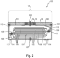
- Fig. 2 illustrates schematically a cross section through an energy storage element 100 according to the invention, wherein this energy storage element is equipped with a stacked electrode-separator assembly 101.
- the housing of the energy storage element 100 is constructed from a cup-shaped housing part 11 and a cover part 12, as already shown in the Figure 1
- the cover part 12 comprises a disk-shaped cover plate 13 with a central opening into which the metallic pole disk 14 is inserted. Between the pole disk 14 and the inner edge of the cover plate 13 there is a gap 15 which is filled with adhesive.
- the adhesive can be, for example, epoxy resin or an acrylate adhesive.
- the electrode-separator assembly 101 shown here in the form of a stack can also be realized, for example, as a cylindrical winding or as a flat winding.
- the stack is formed by the anodes 102 and cathodes 103, which are stacked on top of each other and separated from each other by flat separators 104.
- the electrodes 102, 103 are each formed by a carrier film (current collector film) and a coating with an electrochemically active material. In the case of a button cell, for example, they can be circular.
- copper or nickel foil is used as the carrier foil for the anodes 102.
- An active material based on graphite, silicon (Si), lithium titanium oxide (LTO) or others can be used as the electrochemically active material.
- the carrier foil for the cathode is made of aluminum, for example, and lithium nickel manganese cobalt oxides (NMC), lithium cobalt oxides (LCO), lithium nickel cobalt aluminum oxides (NCA), lithium iron phosphates (LFP) or others can be used as the active material for the cathode.
- uncoated strip-shaped extensions of the current collector foils of the anodes 102 can be welded together (for example via resistance welding, ultrasound or laser).
- the extensions can be welded to an anode conductor 105, for example via resistance welding, ultrasound or laser (welding 106).
- the two welding steps can also be combined in one step.
- the anode conductor 105 can in turn be welded to the cup-shaped housing part 11 by means of resistance welding, ultrasound or laser (welding 107). In the embodiment illustrated here, this welding is provided in the bottom region of the cup-shaped housing part 11.
- uncoated strip-shaped extensions of the current collector foils of the cathodes 103 can be welded to one another and to a cathode conductor 108 (welding 109).
- the welding of the cathode current collectors to one another and the welding to the cathode conductor 108 can also be carried out sequentially or in one step.
- the cathode conductor 108 is welded to the pole disk 14 from the inside (welding 110), whereby this welding can be carried out, for example, by resistance welding, ultrasound or laser from the inside or from the outside.
- the inside of the cover plate 13 is covered with an insulating disk 111. Furthermore, the cathode conductor 108 is provided with an insulating means 115, e.g. an insulating film, for electrical insulation from the housing.
- an insulating means 115 e.g. an insulating film
- the cup-shaped housing part 11 is welded to the cover part 12 in the region of its upper opening (step 112). This is preferably done by laser radiation, which can be applied horizontally and/or vertically.
- the interior of the housing of the energy storage element 100 can be filled with an electrolyte via the activation holes 113 in the base area of the cup-shaped housing part 11.
- the activation holes 113 can then be closed, for example, with a cover plate 114 or the like.
- the closure can be realized, for example, by means of gluing or welding (ultrasonic, resistance or laser).
- the polarity can also be reversed.
- the cover plate 13 can be made of a plastic material, so that only the polarity of the pole disk 14 can be tapped on the upper side of the energy storage element 100 and only the cup-shaped housing part 11 carries the other polarity.
- Fig. 3 shows a concrete embodiment of a cover part 12 according to the invention.
- the cover part 12 is formed by the disk-shaped cover plate 13, in this example a metallic cover plate, and the metallic pole disk 14, which is embedded in the cover plate 13 via an adhesive connection (gap 15 filled with adhesive).
- indentations and undercut areas are present which improve the adhesion of the adhesive and the mechanical connection between the pole disk 14 and the cover plate 13.
- indentations 140 are provided in the area of the outer edge of the pole disk.
- undercut indentations 130 in the shape of a head post are provided.
- the undercut indentations 130 are formed by circular areas that open into the central recess of the cover plate 13 via a narrow web. The areas 130 and 140 allow a particularly stable adhesive connection between the cover plate 13 and the pole disk 14.
- the shapes of the pole disk 14 and the recess of the cover plate 13 can each be round, for example, so that the cover plate 13 is designed as a donut and the pole disk 14 as a round disk.
- This design of the cover part is particularly advantageous with regard to particularly simple production.
Landscapes
- Chemical & Material Sciences (AREA)
- Chemical Kinetics & Catalysis (AREA)
- Electrochemistry (AREA)
- General Chemical & Material Sciences (AREA)
- Engineering & Computer Science (AREA)
- Manufacturing & Machinery (AREA)
- Sealing Battery Cases Or Jackets (AREA)
Priority Applications (2)
| Application Number | Priority Date | Filing Date | Title |
|---|---|---|---|
| EP23188551.8A EP4498463A1 (fr) | 2023-07-28 | 2023-07-28 | Élément accumulateur d'énergie électrochimique, en particulier sous la forme d'une pile bouton |
| PCT/EP2024/071065 WO2025026853A1 (fr) | 2023-07-28 | 2024-07-24 | Élément de stockage d'énergie électrochimique et procédé de production |
Applications Claiming Priority (1)
| Application Number | Priority Date | Filing Date | Title |
|---|---|---|---|
| EP23188551.8A EP4498463A1 (fr) | 2023-07-28 | 2023-07-28 | Élément accumulateur d'énergie électrochimique, en particulier sous la forme d'une pile bouton |
Publications (1)
| Publication Number | Publication Date |
|---|---|
| EP4498463A1 true EP4498463A1 (fr) | 2025-01-29 |
Family
ID=87551043
Family Applications (1)
| Application Number | Title | Priority Date | Filing Date |
|---|---|---|---|
| EP23188551.8A Withdrawn EP4498463A1 (fr) | 2023-07-28 | 2023-07-28 | Élément accumulateur d'énergie électrochimique, en particulier sous la forme d'une pile bouton |
Country Status (1)
| Country | Link |
|---|---|
| EP (1) | EP4498463A1 (fr) |
Citations (8)
| Publication number | Priority date | Publication date | Assignee | Title |
|---|---|---|---|---|
| DE102009017514A1 (de) | 2009-04-04 | 2010-10-07 | Varta Microbattery Gmbh | Knopfzelle ohne Bördelung |
| CN106159350A (zh) | 2015-04-27 | 2016-11-23 | 深圳金山电池有限公司 | 一种纽扣型锂离子二次电池及其制备方法 |
| DE102017216876A1 (de) * | 2017-09-25 | 2019-03-28 | Lithium Energy and Power GmbH & Co. KG | Deckelbaugruppe und Verfahren zum Herstellen derselben |
| EP3813171A1 (fr) | 2019-09-05 | 2021-04-28 | Chongqing VDL Electronics Co., Ltd. | Pile bouton pour améliorer le taux d'utilisation d'espace radial |
| CN113497297A (zh) * | 2021-06-28 | 2021-10-12 | 东莞锂微电子科技有限公司 | 一种电池、用电装置及电池的制备方法 |
| EP3920297A1 (fr) | 2020-06-05 | 2021-12-08 | Chongqing VDL Electronics Co., Ltd. | Batterie au lithium-ion de type bouton avec boîtier métallique |
| EP3940877A1 (fr) * | 2020-05-18 | 2022-01-19 | Ningde Amperex Technology Ltd. | Batterie et dispositif alimenté pourvu de la batterie |
| US20230049098A1 (en) * | 2020-04-30 | 2023-02-16 | Murata Manufacturing Co., Ltd. | Secondary battery |
-
2023
- 2023-07-28 EP EP23188551.8A patent/EP4498463A1/fr not_active Withdrawn
Patent Citations (8)
| Publication number | Priority date | Publication date | Assignee | Title |
|---|---|---|---|---|
| DE102009017514A1 (de) | 2009-04-04 | 2010-10-07 | Varta Microbattery Gmbh | Knopfzelle ohne Bördelung |
| CN106159350A (zh) | 2015-04-27 | 2016-11-23 | 深圳金山电池有限公司 | 一种纽扣型锂离子二次电池及其制备方法 |
| DE102017216876A1 (de) * | 2017-09-25 | 2019-03-28 | Lithium Energy and Power GmbH & Co. KG | Deckelbaugruppe und Verfahren zum Herstellen derselben |
| EP3813171A1 (fr) | 2019-09-05 | 2021-04-28 | Chongqing VDL Electronics Co., Ltd. | Pile bouton pour améliorer le taux d'utilisation d'espace radial |
| US20230049098A1 (en) * | 2020-04-30 | 2023-02-16 | Murata Manufacturing Co., Ltd. | Secondary battery |
| EP3940877A1 (fr) * | 2020-05-18 | 2022-01-19 | Ningde Amperex Technology Ltd. | Batterie et dispositif alimenté pourvu de la batterie |
| EP3920297A1 (fr) | 2020-06-05 | 2021-12-08 | Chongqing VDL Electronics Co., Ltd. | Batterie au lithium-ion de type bouton avec boîtier métallique |
| CN113497297A (zh) * | 2021-06-28 | 2021-10-12 | 东莞锂微电子科技有限公司 | 一种电池、用电装置及电池的制备方法 |
Similar Documents
| Publication | Publication Date | Title |
|---|---|---|
| EP2771922B1 (fr) | Piles boutons comprenant un ensemble d'électrodes enroulées | |
| EP2443691B1 (fr) | Pile bouton à électrode enroulée et son procédé de fabrication | |
| WO2022023321A1 (fr) | Cellule de stockage d'énergie et procédé de production | |
| EP3041062A1 (fr) | Cellule électrochimique | |
| WO2024046982A1 (fr) | Cellule de stockage d'énergie et procédé de fabrication d'une cellule de stockage d'énergie de ce type | |
| WO2021219732A1 (fr) | Pile électrochimique au lithium-ion secondaire | |
| WO2024052435A1 (fr) | Élément de stockage d'énergie et procédé de fabrication d'un tel élément de stockage d'énergie | |
| WO2016116317A1 (fr) | Enroulement d'électrodes pour élément galvanique et son procédé de production | |
| DE102014222332A1 (de) | Schichtaufbau für ein galvanisches Element | |
| EP3745490B1 (fr) | Procédé de fabrication d'une batterie et batterie fabriquée selon ledit procédé | |
| EP4258397A1 (fr) | Élément d'accumulation d'énergie pourvu de boîtier cylindrique et procédé de fabrication | |
| EP4187688A1 (fr) | Cellule d'accumulateur d'énergie, composite de cellules d'accumulateur d'énergie et procédé de fabrication | |
| EP4135088A1 (fr) | Élément accumulateur d'énergie, composite constitué d'éléments accumulateurs d'énergie et procédé de fabrication | |
| EP4498463A1 (fr) | Élément accumulateur d'énergie électrochimique, en particulier sous la forme d'une pile bouton | |
| WO2025026853A1 (fr) | Élément de stockage d'énergie électrochimique et procédé de production | |
| EP4197051B1 (fr) | Élément lithium-ion à haute densité énergétique spécifique | |
| EP4539179A1 (fr) | Élément de stockage d'énergie électrochimique, en particulier sous la forme d'une cellule miniature | |
| WO2023057112A1 (fr) | Élément de stockage d'énergie et son procédé de production | |
| DE102022113906A1 (de) | Energiespeicherzelle mit zylindrischem Gehäuse und Verfahren zur Herstellung | |
| EP4672288A1 (fr) | Élément de stockage d'énergie électrochimique et procédé de fabrication | |
| EP4465393A1 (fr) | Pile bouton électrochimique et procédé de fabrication | |
| EP4164049B1 (fr) | Élément d'accumulateur d'énergie et procédé de fabrication | |
| EP4329083A1 (fr) | Élément électrochimique accumulateur d'énergie et procédé de fabrication | |
| EP4496082A1 (fr) | Élément accumulateur d'énergie électrochimique doté d'une partie de tôle de contact et son procédé de fabrication | |
| EP4456270A1 (fr) | Élément accumulateur d'énergie électrochimique |
Legal Events
| Date | Code | Title | Description |
|---|---|---|---|
| PUAI | Public reference made under article 153(3) epc to a published international application that has entered the european phase |
Free format text: ORIGINAL CODE: 0009012 |
|
| STAA | Information on the status of an ep patent application or granted ep patent |
Free format text: STATUS: THE APPLICATION HAS BEEN PUBLISHED |
|
| AK | Designated contracting states |
Kind code of ref document: A1 Designated state(s): AL AT BE BG CH CY CZ DE DK EE ES FI FR GB GR HR HU IE IS IT LI LT LU LV MC ME MK MT NL NO PL PT RO RS SE SI SK SM TR |
|
| STAA | Information on the status of an ep patent application or granted ep patent |
Free format text: STATUS: THE APPLICATION IS DEEMED TO BE WITHDRAWN |
|
| 18D | Application deemed to be withdrawn |
Effective date: 20250730 |