EP4498482A1 - Module de batterie - Google Patents
Module de batterie Download PDFInfo
- Publication number
- EP4498482A1 EP4498482A1 EP24180375.8A EP24180375A EP4498482A1 EP 4498482 A1 EP4498482 A1 EP 4498482A1 EP 24180375 A EP24180375 A EP 24180375A EP 4498482 A1 EP4498482 A1 EP 4498482A1
- Authority
- EP
- European Patent Office
- Prior art keywords
- insulation sheet
- battery module
- refractory layer
- aerogel
- cells
- Prior art date
- Legal status (The legal status is an assumption and is not a legal conclusion. Google has not performed a legal analysis and makes no representation as to the accuracy of the status listed.)
- Pending
Links
Images


Classifications
-
- H—ELECTRICITY
- H01—ELECTRIC ELEMENTS
- H01M—PROCESSES OR MEANS, e.g. BATTERIES, FOR THE DIRECT CONVERSION OF CHEMICAL ENERGY INTO ELECTRICAL ENERGY
- H01M50/00—Constructional details or processes of manufacture of the non-active parts of electrochemical cells other than fuel cells, e.g. hybrid cells
- H01M50/20—Mountings; Secondary casings or frames; Racks, modules or packs; Suspension devices; Shock absorbers; Transport or carrying devices; Holders
- H01M50/289—Mountings; Secondary casings or frames; Racks, modules or packs; Suspension devices; Shock absorbers; Transport or carrying devices; Holders characterised by spacing elements or positioning means within frames, racks or packs
- H01M50/293—Mountings; Secondary casings or frames; Racks, modules or packs; Suspension devices; Shock absorbers; Transport or carrying devices; Holders characterised by spacing elements or positioning means within frames, racks or packs characterised by the material
-
- B—PERFORMING OPERATIONS; TRANSPORTING
- B32—LAYERED PRODUCTS
- B32B—LAYERED PRODUCTS, i.e. PRODUCTS BUILT-UP OF STRATA OF FLAT OR NON-FLAT, e.g. CELLULAR OR HONEYCOMB, FORM
- B32B19/00—Layered products comprising a layer of natural mineral fibres or particles, e.g. asbestos, mica
- B32B19/04—Layered products comprising a layer of natural mineral fibres or particles, e.g. asbestos, mica next to another layer of the same or of a different material
-
- B—PERFORMING OPERATIONS; TRANSPORTING
- B32—LAYERED PRODUCTS
- B32B—LAYERED PRODUCTS, i.e. PRODUCTS BUILT-UP OF STRATA OF FLAT OR NON-FLAT, e.g. CELLULAR OR HONEYCOMB, FORM
- B32B5/00—Layered products characterised by the non- homogeneity or physical structure, i.e. comprising a fibrous, filamentary, particulate or foam layer; Layered products characterised by having a layer differing constitutionally or physically in different parts
- B32B5/18—Layered products characterised by the non- homogeneity or physical structure, i.e. comprising a fibrous, filamentary, particulate or foam layer; Layered products characterised by having a layer differing constitutionally or physically in different parts characterised by features of a layer of foamed material
-
- B—PERFORMING OPERATIONS; TRANSPORTING
- B32—LAYERED PRODUCTS
- B32B—LAYERED PRODUCTS, i.e. PRODUCTS BUILT-UP OF STRATA OF FLAT OR NON-FLAT, e.g. CELLULAR OR HONEYCOMB, FORM
- B32B7/00—Layered products characterised by the relation between layers; Layered products characterised by the relative orientation of features between layers, or by the relative values of a measurable parameter between layers, i.e. products comprising layers having different physical, chemical or physicochemical properties; Layered products characterised by the interconnection of layers
- B32B7/02—Physical, chemical or physicochemical properties
- B32B7/027—Thermal properties
-
- B—PERFORMING OPERATIONS; TRANSPORTING
- B60—VEHICLES IN GENERAL
- B60L—PROPULSION OF ELECTRICALLY-PROPELLED VEHICLES; SUPPLYING ELECTRIC POWER FOR AUXILIARY EQUIPMENT OF ELECTRICALLY-PROPELLED VEHICLES; ELECTRODYNAMIC BRAKE SYSTEMS FOR VEHICLES IN GENERAL; MAGNETIC SUSPENSION OR LEVITATION FOR VEHICLES; MONITORING OPERATING VARIABLES OF ELECTRICALLY-PROPELLED VEHICLES; ELECTRIC SAFETY DEVICES FOR ELECTRICALLY-PROPELLED VEHICLES
- B60L50/00—Electric propulsion with power supplied within the vehicle
- B60L50/50—Electric propulsion with power supplied within the vehicle using propulsion power supplied by batteries or fuel cells
- B60L50/60—Electric propulsion with power supplied within the vehicle using propulsion power supplied by batteries or fuel cells using power supplied by batteries
- B60L50/64—Constructional details of batteries specially adapted for electric vehicles
-
- F—MECHANICAL ENGINEERING; LIGHTING; HEATING; WEAPONS; BLASTING
- F16—ENGINEERING ELEMENTS AND UNITS; GENERAL MEASURES FOR PRODUCING AND MAINTAINING EFFECTIVE FUNCTIONING OF MACHINES OR INSTALLATIONS; THERMAL INSULATION IN GENERAL
- F16L—PIPES; JOINTS OR FITTINGS FOR PIPES; SUPPORTS FOR PIPES, CABLES OR PROTECTIVE TUBING; MEANS FOR THERMAL INSULATION IN GENERAL
- F16L59/00—Thermal insulation in general
- F16L59/02—Shape or form of insulating materials, with or without coverings integral with the insulating materials
- F16L59/029—Shape or form of insulating materials, with or without coverings integral with the insulating materials layered
-
- H—ELECTRICITY
- H01—ELECTRIC ELEMENTS
- H01M—PROCESSES OR MEANS, e.g. BATTERIES, FOR THE DIRECT CONVERSION OF CHEMICAL ENERGY INTO ELECTRICAL ENERGY
- H01M10/00—Secondary cells; Manufacture thereof
- H01M10/60—Heating or cooling; Temperature control
- H01M10/65—Means for temperature control structurally associated with the cells
- H01M10/658—Means for temperature control structurally associated with the cells by thermal insulation or shielding
-
- H—ELECTRICITY
- H01—ELECTRIC ELEMENTS
- H01M—PROCESSES OR MEANS, e.g. BATTERIES, FOR THE DIRECT CONVERSION OF CHEMICAL ENERGY INTO ELECTRICAL ENERGY
- H01M50/00—Constructional details or processes of manufacture of the non-active parts of electrochemical cells other than fuel cells, e.g. hybrid cells
- H01M50/20—Mountings; Secondary casings or frames; Racks, modules or packs; Suspension devices; Shock absorbers; Transport or carrying devices; Holders
- H01M50/204—Racks, modules or packs for multiple batteries or multiple cells
-
- H—ELECTRICITY
- H01—ELECTRIC ELEMENTS
- H01M—PROCESSES OR MEANS, e.g. BATTERIES, FOR THE DIRECT CONVERSION OF CHEMICAL ENERGY INTO ELECTRICAL ENERGY
- H01M50/00—Constructional details or processes of manufacture of the non-active parts of electrochemical cells other than fuel cells, e.g. hybrid cells
- H01M50/20—Mountings; Secondary casings or frames; Racks, modules or packs; Suspension devices; Shock absorbers; Transport or carrying devices; Holders
- H01M50/233—Mountings; Secondary casings or frames; Racks, modules or packs; Suspension devices; Shock absorbers; Transport or carrying devices; Holders characterised by physical properties of casings or racks, e.g. dimensions
- H01M50/24—Mountings; Secondary casings or frames; Racks, modules or packs; Suspension devices; Shock absorbers; Transport or carrying devices; Holders characterised by physical properties of casings or racks, e.g. dimensions adapted for protecting batteries from their environment, e.g. from corrosion
-
- H—ELECTRICITY
- H01—ELECTRIC ELEMENTS
- H01M—PROCESSES OR MEANS, e.g. BATTERIES, FOR THE DIRECT CONVERSION OF CHEMICAL ENERGY INTO ELECTRICAL ENERGY
- H01M50/00—Constructional details or processes of manufacture of the non-active parts of electrochemical cells other than fuel cells, e.g. hybrid cells
- H01M50/20—Mountings; Secondary casings or frames; Racks, modules or packs; Suspension devices; Shock absorbers; Transport or carrying devices; Holders
- H01M50/249—Mountings; Secondary casings or frames; Racks, modules or packs; Suspension devices; Shock absorbers; Transport or carrying devices; Holders specially adapted for aircraft or vehicles, e.g. cars or trains
-
- B—PERFORMING OPERATIONS; TRANSPORTING
- B32—LAYERED PRODUCTS
- B32B—LAYERED PRODUCTS, i.e. PRODUCTS BUILT-UP OF STRATA OF FLAT OR NON-FLAT, e.g. CELLULAR OR HONEYCOMB, FORM
- B32B2255/00—Coating on the layer surface
- B32B2255/20—Inorganic coating
-
- B—PERFORMING OPERATIONS; TRANSPORTING
- B32—LAYERED PRODUCTS
- B32B—LAYERED PRODUCTS, i.e. PRODUCTS BUILT-UP OF STRATA OF FLAT OR NON-FLAT, e.g. CELLULAR OR HONEYCOMB, FORM
- B32B2255/00—Coating on the layer surface
- B32B2255/26—Polymeric coating
-
- B—PERFORMING OPERATIONS; TRANSPORTING
- B32—LAYERED PRODUCTS
- B32B—LAYERED PRODUCTS, i.e. PRODUCTS BUILT-UP OF STRATA OF FLAT OR NON-FLAT, e.g. CELLULAR OR HONEYCOMB, FORM
- B32B2262/00—Composition or structural features of fibres which form a fibrous or filamentary layer or are present as additives
- B32B2262/10—Inorganic fibres
- B32B2262/101—Glass fibres
-
- B—PERFORMING OPERATIONS; TRANSPORTING
- B32—LAYERED PRODUCTS
- B32B—LAYERED PRODUCTS, i.e. PRODUCTS BUILT-UP OF STRATA OF FLAT OR NON-FLAT, e.g. CELLULAR OR HONEYCOMB, FORM
- B32B2266/00—Composition of foam
- B32B2266/12—Gel
- B32B2266/126—Aerogel, i.e. a supercritically dried gel
-
- B—PERFORMING OPERATIONS; TRANSPORTING
- B32—LAYERED PRODUCTS
- B32B—LAYERED PRODUCTS, i.e. PRODUCTS BUILT-UP OF STRATA OF FLAT OR NON-FLAT, e.g. CELLULAR OR HONEYCOMB, FORM
- B32B2307/00—Properties of the layers or laminate
- B32B2307/30—Properties of the layers or laminate having particular thermal properties
- B32B2307/304—Insulating
-
- B—PERFORMING OPERATIONS; TRANSPORTING
- B32—LAYERED PRODUCTS
- B32B—LAYERED PRODUCTS, i.e. PRODUCTS BUILT-UP OF STRATA OF FLAT OR NON-FLAT, e.g. CELLULAR OR HONEYCOMB, FORM
- B32B2307/00—Properties of the layers or laminate
- B32B2307/30—Properties of the layers or laminate having particular thermal properties
- B32B2307/306—Resistant to heat
- B32B2307/3065—Flame resistant or retardant, fire resistant or retardant
-
- B—PERFORMING OPERATIONS; TRANSPORTING
- B32—LAYERED PRODUCTS
- B32B—LAYERED PRODUCTS, i.e. PRODUCTS BUILT-UP OF STRATA OF FLAT OR NON-FLAT, e.g. CELLULAR OR HONEYCOMB, FORM
- B32B2457/00—Electrical equipment
- B32B2457/10—Batteries
-
- Y—GENERAL TAGGING OF NEW TECHNOLOGICAL DEVELOPMENTS; GENERAL TAGGING OF CROSS-SECTIONAL TECHNOLOGIES SPANNING OVER SEVERAL SECTIONS OF THE IPC; TECHNICAL SUBJECTS COVERED BY FORMER USPC CROSS-REFERENCE ART COLLECTIONS [XRACs] AND DIGESTS
- Y02—TECHNOLOGIES OR APPLICATIONS FOR MITIGATION OR ADAPTATION AGAINST CLIMATE CHANGE
- Y02E—REDUCTION OF GREENHOUSE GAS [GHG] EMISSIONS, RELATED TO ENERGY GENERATION, TRANSMISSION OR DISTRIBUTION
- Y02E60/00—Enabling technologies; Technologies with a potential or indirect contribution to GHG emissions mitigation
- Y02E60/10—Energy storage using batteries
Definitions
- Example embodiments relate to a battery module, a method of manufacturing the battery module, and a battery pack including the battery module.
- a secondary battery is a power storage system that is configured to convert electrical energy into chemical energy, to store the chemical energy, and to provide high energy density.
- a secondary battery is typically rechargeable and is widely used in information technology (IT) devices such as, e.g., smartphones, cellular phones, laptop computers, tablet computers, and the like.
- IT information technology
- Secondary batteries typically exhibit characteristics such as, e.g., high density, high output, and stability.
- one cell may overheat and may go into thermal runaway for various reasons, which may adversely affect other cells adjacent thereto, and therefore it may be advantageous to thermally isolate neighboring cells from each other.
- a plate or an insulating resin sheet is disposed between cells to isolate and insulate neighboring cells from each other.
- Example embodiments include a battery module having desired, advantageous or improved thermal insulation, fire resistance, and flame retardancy or non-flammability to inhibit propagation of heat in a cell to cells adjacent thereto due to thermal runaway in the cell, a method of manufacturing the battery module, and a battery pack including the battery module.
- An example embodiment includes a battery module including a plurality of cells, an insulation sheet between the plurality of cells, the insulation sheet having an upper surface and a lower surface arranged so as to face cells adjacent thereto, respectively, and a refractory layer formed on at least one side surface part of a border side surface between the upper surface and the lower surface of the insulation sheet, wherein the refractory layer includes an inorganic binder.
- Each, or one or more, of the cells may be or include a secondary battery cell.
- the insulation sheet may include a first substrate, a second substrate, and an aerogel layer between the first substrate and the second substrate.
- Each, or one or more, of the first substrate and the second substrate may include at least one of a resin, a metal, an inorganic material other than the metal, and a composite thereof.
- the aerogel layer may include an aerogel, a fibrous support, and a functional material including a binder, a dispersant, or a combination thereof.
- the aerogel may have a Brunauer, Emmett and Teller (BET) specific surface area in a range of 500 m 2 /g to 1,000 m 2 /g.
- BET Brunauer, Emmett and Teller
- the fibrous support may be at least one of natural fiber, silica fiber, glass fiber, ceramic fiber, carbon fiber, graphite fiber, mineral fiber, and polymer fiber.
- the binder may include an aqueous polymer binder, and the aqueous polymer binder may be or include at least one of a water-based polymer, an anionic water-soluble polymer, a cationic water-soluble polymer, and a water-dispersible polymer.
- the dispersant may be at least one of a surfactant and a phosphate-based salt.
- the aerogel may be included so as to account for 10 wt% to 90 wt%, the fibrous support may be included so as to account for 5 wt% to 70 wt%, and the functional material may be included so as to account for 0.5 wt% to 20 wt%, based on the total amount of the aerogel layer.
- the inorganic binder may be at least one of aluminate, silicate, phosphate, sulfate, and chloride.
- the inorganic binder may be at least one of ordinary calcium aluminate, pure calcium aluminate, sodium silicate, potassium silicate, lithium silicate, sodium phosphate, potassium phosphate, magnesium phosphate, zinc phosphate, calcium phosphate, aluminum phosphate, iron phosphate, sodium dihydrogen phosphate, sodium tripolyphosphate, sodium hexametaphosphate, magnesium sulfate, aluminum sulfate, iron (III) sulfate, magnesium chloride, iron (III) chloride, and polyaluminum chloride.
- the refractory layer may be formed on an upper side surface part of the side surface of the insulation sheet, upper and lower side surface parts of the side surface of the insulation sheet, or the entirety of the side surface of the insulation sheet.
- the thickness of the refractory layer formed on the upper side surface part of the side surface of the insulation sheet may be 120% to 400% of the thickness of the refractory layer formed on the lower side surface part of the side surface of the insulation sheet.
- the battery module may include an empty space other than a space in which the cells and the insulation sheet are located, the refractory layer may be configured to wrap the side surface of the insulation sheet and a part or the entirety of a side surface of each of the cells adjacent thereto in the empty space formed in an upper part of the battery module, and the refractory layer may be formed such that the thickness of a central part of the refractory layer is greater than the thickness of opposite edges of the refractory layer.
- Another example embodiment includes a method of manufacturing a battery module, the method including disposing a plurality of cells, disposing an insulation sheet between the plurality of cells such that an upper surface and a lower surface of the insulation sheet face cells adjacent thereto, respectively, and forming a refractory layer on at least one side surface part of a border side surface between the upper surface and the lower surface of the insulation sheet, wherein the refractory layer includes an inorganic binder.
- Forming the refractory layer may be performed before or after disposing the insulation sheet between the plurality of cells.
- Forming the refractory layer may be performed by at least one of gap coating, dip coating, slot die coating, blade coating, dispensing, printing, brush coating, and potting using a solution of an inorganic binder dispersed in a solvent.
- a further example embodiment includes a battery pack including the battery module.
- example embodiments will be described in detail such that a person having ordinary skill in the art can readily implement the example embodiments.
- example embodiments may be implemented in many different forms and are not limited to the example embodiments described herein.
- a battery module includes a plurality of cells, an insulation sheet between the plurality of cells, the insulation sheet having an upper surface and a lower surface configured to face cells adjacent thereto, respectively, and a refractory layer on at least one side surface part of a border side surface between the upper surface and the lower surface of the insulation sheet, wherein the refractory layer includes an inorganic binder.
- the refractory layer may be formed on at least one of an upper side surface part, a lower side surface part, a front side surface part, and a rear side surface part of the border side surface of the insulation sheet.
- the refractory layer may be formed on the upper side surface part of the border side surface of the insulation sheet, the upper side surface part and the lower side surface part of the border side surface of the insulation sheet, or the entirety of the border side surface of the insulation sheet.
- the refractory layer may be essentially formed on the upper side surface part of the border side surface of the insulation sheet.
- the refractory layer may be formed so as to cover a part of the entirety of an externally exposed portion of the surface of the insulation sheet that does not face the cell.
- the refractory layer may be formed so as to further cover a part or the entirety of the cell adjacent to the insulation sheet.
- the battery module having the above structure may have desired, advantageous or improved thermal insulation, fire resistance, and flame retardancy or non-flammability, thereby inhibiting propagation of heat and flames in a cell to cells adjacent thereto due to thermal runaway in the cell.
- a border side surface of the insulation sheet may be exposed to air, and propagation of heat or flames to the exposed side surface may occur during thermal runaway, which may be effectively inhibited by a battery module according to an example embodiment that includes a refractory layer.
- the insulation sheet may have desired, advantageous or improved compressibility, mechanical strength, and dimensional stability, and may reduce or prevent detachment of an aerogel layer due to external impact, thereby improving workability and reducing or preventing contamination of an instrument.
- the cell may be a secondary battery cell.
- the secondary battery cell may be, for example, a lithium secondary battery.
- the lithium secondary battery may be manufactured in various forms, such as, e.g., a lithium ion battery, an all-solid-state battery, a lithium metal battery, and the like.
- the lithium secondary battery may have a structure in which a positive electrode plate having a positive electrode active material applied thereto and a negative electrode plate having a negative electrode active material applied thereto are arranged such that a separator is interposed therebetween, and the lithium secondary battery may be received in a battery case together with an electrolytic solution in a sealed state to constitute a secondary battery cell.
- the secondary battery cell may be classified as, e.g., a cylindrical secondary battery cell, a prismatic secondary battery cell, or a pouch-shaped secondary battery cell, and a plurality of secondary battery cells may be connected to each other in series or in parallel to constitute a battery module.
- the secondary battery cell may require a high degree of stability so that, e.g., when overcharged, the positive electrode active material or an electrolyte may be subjected to decomposition and other side reactions, whereby heat may be emitted from the secondary battery, resulting in a possible explosion of the secondary battery cell.
- an insulation sheet may be disposed between cells, and a refractory layer may be provided on a side surface of the insulation sheet, whereby the battery module may have desired, advantageous or improved thermal insulation, fire resistance, and flame retardancy or non-flammability, and therefore it is possible to reduce or inhibit propagation of heat and flames in a cell to cells adjacent thereto due to thermal runaway in the cell.
- a "left” surface of a cuboid is referred to as a first side surface
- a "right” surface of the cuboid may be referred to as a second side surface opposite the first side surface.
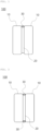
- FIG. 1 is a schematic view showing a part of a battery module according to an example embodiment, the battery module including an insulation sheet disposed between a plurality of cells, wherein a refractory layer is formed on an upper side surface part of a side surface of the insulation sheet.
- flames generated in one cell may be hindered or prevented from moving to an empty space in the battery module through the upper side surface part of the side surface of the insulation sheet, thereby effectively reducing or preventing the propagation of the flames to cells adjacent thereto.
- the battery module 100 may include a plurality of cells 10, and may include an insulation sheet 20 provided between the plurality of cells 10.
- the insulation sheet 20 may be disposed such that an upper surface and a lower surface of the insulation sheet 20 face cells 10 adjacent thereto, respectively.
- the battery module 100 may further include a refractory layer 30 formed on an upper side surface part of a side surface of the insulation sheet 20.
- the refractory layer may be formed on upper and lower side surface parts of the side surface of the insulation sheet, or on substantially the entirety of the side surface of the insulation sheet.
- the terms “upper side surface part” and “lower side surface part” refer to surfaces formed at an upper side and a lower side of the insulation sheet, respectively, based on the form in which the insulation sheet is disposed.
- the refractory layer may be formed on substantially the entirety of the side surface of the insulation sheet.
- flames generated in one cell may be hindered or prevented from moving to the empty space in the battery module through the side surface of the insulation sheet, thereby effectively reducing or preventing the propagation of the flames to cells adjacent thereto.
- the refractory layer may be formed on the upper side surface part and the lower side surface part of the side surface of the insulation sheet, which are opposite to each other. In this case, installation of the refractory layer may be reduced or minimized, and flames generated in one cell may be hindered or prevented from moving to the empty space in the battery module through the upper side surface part and the lower side surface part of the side surface of the insulation sheet, thereby more effectively reducing or preventing the propagation of flames to cells adjacent thereto.
- FIG. 2 is a schematic view showing a part of an example battery module including an insulation sheet disposed between a plurality of cells, wherein a refractory layer is formed on an upper side surface part and a lower side surface part of a side surface of the insulation sheet.
- the battery module 100 may include a plurality of cells 10, and may include an insulation sheet 20 between the plurality of cells 10.
- the insulation sheet 20 may be such that an upper surface and a lower surface of the insulation sheet face cells 10 adjacent thereto, respectively.
- the battery module 100 may further include a refractory layer 30 formed on an upper side surface part and a lower side surface part of a side surface of the insulation sheet 20.
- the refractory layer formed on a front side surface part and a rear side surface part of the side surface of the insulation sheet is not shown in a sectional view, and therefore the refractory layer formed on the front side surface part and the rear side surface part of the side surface of the insulation sheet is not shown in FIG. 2 .
- the thickness of the refractory layer formed on the upper side surface part of the side surface of the insulation sheet may be 120% to 400%, 150% to 350%, or 200% to 350% of the thickness of the refractory layer formed on the lower side surface part of the side surface of the insulation sheet.
- the thickness of the refractory layer formed on the upper side surface part of the side surface of the insulation sheet may be at least one of 1.2 to 4 times, 1.5 to 3.5 times, and 2 to 3.5 times the thickness of the refractory layer formed on the lower side surface part of the side surface of the insulation sheet.
- FIG. 3 is a schematic view showing a part of a battery module including an insulation sheet between a plurality of cells, wherein a refractory layer is formed on an upper side surface part and a lower side surface part of a side surface of the insulation sheet, and the thickness of the refractory layer formed on the upper side surface part is greater than the thickness of the refractory layer formed on the lower side surface part.
- the battery module 100 may include a plurality of cells 10, and may include an insulation sheet 20 between the plurality of cells 10.
- the insulation sheet 20 may be such that an upper surface and a lower surface of the insulation sheet face cells 10 adjacent thereto, respectively.
- the battery module 100 may further include a refractory layer 30 formed on an upper side surface part and a lower side surface part of a side surface of the insulation sheet 20, wherein the thickness of the refractory layer formed on the upper side surface part may be greater than the thickness of the refractory layer formed on the lower side surface part.
- the battery module may include an empty space other than a space in which the cells and the insulation sheet are disposed
- the refractory layer may be formed so as to wrap the side surface of the insulation sheet and a part or the entirety of a side surface of each of the cells adjacent thereto in the empty space formed in an upper part of the battery module
- the refractory layer may be formed such that the thickness of a central part of the refractory layer is greater than the thickness of opposite edges of the refractory layer.
- the refractory layer may be formed in a trapezoidal shape, a dome shape, or the like.
- the refractory layer is formed such that the thickness of the central part of the refractory layer is greater than the thickness of the opposite edges of the refractory layer, as described above, it is possible to hinder or prevent flames and heat in one cell from being transferred to cells adjacent thereto through a vent located in the center in a planar direction of the cell during thermal runaway in the cell through heat and flame shielding at the central part of the refractory layer, and therefore it is possible to delay or prevent further thermal runaway.
- FIG. 4 is a schematic view showing a part of a battery module including an insulation sheet between a plurality of cells, wherein a refractory layer is formed on an upper side surface part of a side surface of the insulation sheet, and the refractory layer is formed in a trapezoidal shape.
- the battery module 100 may include a plurality of cells 10, and may include an insulation sheet 20 between the plurality of cells 10.
- the insulation sheet 20 may be such that an upper surface and a lower surface of the insulation sheet face cells 10 adjacent thereto, respectively.
- the battery module 100 may further include a refractory layer 30 formed on an upper side surface part of a side surface of the insulation sheet 20.
- the refractory layer 30 may be formed in a trapezoidal shape in which the thickness of a central part of the refractory layer may be greater than the thickness of opposite edges of the refractory layer.
- the refractory layer may also be formed on a lower side surface part of the side surface of the insulation sheet, wherein the thickness of the refractory layer formed on the lower side surface part may be less than the thickness of the refractory layer formed on the upper side surface part.
- FIG. 5 is a schematic view showing a part of a battery module including an insulation sheet between a plurality of cells, wherein a refractory layer is formed on an upper side surface part of a side surface of the insulation sheet, and the refractory layer is formed in a dome shape.
- the battery module 100 may include a plurality of cells 10, and may include an insulation sheet 20 between the plurality of cells 10.
- the insulation sheet 20 may be such that an upper surface and a lower surface of the insulation sheet face cells 10 adjacent thereto, respectively.
- the battery module 100 may further include a refractory layer 30 formed on an upper side surface part of a side surface of the insulation sheet 20, wherein the refractory layer 30 may have a dome shape in which the thickness of a central part of the refractory layer is greater than the thickness of opposite edges of the refractory layer.
- the refractory layer may also be formed on a lower side surface part of the side surface of the insulation sheet, wherein the thickness of the refractory layer formed on the lower side surface part may be lower than the thickness of the refractory layer formed on the upper side surface part.
- the insulation sheet may include a first substrate, a second substrate, and an aerogel layer between the first substrate and the second substrate.
- the first substrate and the second substrate may form an upper surface and a lower surface of the insulation sheet, respectively, and may be configured to face cells adjacent thereto, respectively.
- the insulation sheet may include a border side surface provided between the upper surface and the lower surface of the insulation sheet.
- FIG. 6 is a schematic view showing the structure of an insulation sheet according to an example embodiment.
- the insulation sheet 20 may have a structure including a first substrate 21, a second substrate 22, and an aerogel layer 23 between the first substrate 21 and the second substrate 22.
- the first substrate 21 and the second substrate 22 may form an upper surface and a lower surface of the insulation sheet 20, respectively, and may be configured to face cells 10 adjacent thereto, respectively.
- Each, or at least one of, the first substrate and the second substrate may be made of or include at least one of, without being limited to, a resin, a metal, and an inorganic material other than the metal, or may be made of or include a composite thereof.
- the form of the substrate may be, without being limited to, a film, a membrane, a sheet, and the like.
- the resin may be at least one of, for example, polyethylene, polypropylene, polystyrene, polyethylene terephthalate, and polyamide.
- the metal may be or include at least one of, for example, copper, nickel, cobalt, iron, chromium, vanadium, palladium, ruthenium, rhodium, molybdenum, tungsten, iridium, silver, gold, and platinum.
- the substrate may be subjected to anticorrosion treatment or insulating treatment as needed.
- the inorganic material may be or include at least one of calcium carbonate (CaCO 3 ), talc, and mica.
- each, or at least one of, the first substrate and the second substrate may include an inorganic material, and as another example, the substrate may include mica. In this case, thermal insulation, durability, etc. of the insulation sheet may be improved.
- the aerogel layer may include an aerogel, a fibrous support, and a functional material including a binder, a dispersant, or a combination thereof.
- the aerogel may have a BET specific surface area of 500 m 2 /g to 1,000 m 2 /g.
- the aerogel may have a BET specific surface area of 500 m 2 /g to 950 m 2 /g, 550 m 2 /g to 950 m 2 /g, or 600 m 2 /g to 900 m 2 /g.
- the aerogel having a BET specific surface area value within the above range is included, it is possible to provide an insulation sheet capable of effectively reducing or preventing heat transfer and heat propagation between a plurality of cells.
- the BET is measured according to DIN ISO 9277.
- the average particle size D50 of the aerogel may be 5 um to 200 um, 10 um to 100 um, or 20 um to 50 um.
- thermal insulation may be improved, whereby heat transfer between the plurality of cells may be delayed.
- the average particle size D50 may be measured, for example, using a laser diffraction method, or scanning electron microscopy (SEM), wherein the average particle size D50 of particles may be defined as the particle size at 50% of the particle size distribution (the particle size corresponding to cumulative 50% of the volume of the particle size distribution).
- SEM scanning electron microscopy
- the content of the aerogel may be 10 wt% to 90 wt%, 30 wt% to 70 wt%, or 40 wt% to 60 wt%, based on the total amount of the aerogel layer.
- thermal insulation of the insulation sheet may be improved.
- the fibrous support may be included in the aerogel layer, whereby durability of the insulation sheet formed using the same may be improved.
- the fibrous support may include fiber used as a support made of or include, e.g., an ordinary insulating material.
- the fibrous support may be or include at least one of natural fiber, silica fiber, glass fiber, ceramic fiber, carbon fiber, graphite fiber, mineral fiber, and polymer fiber.
- the fibrous support may include, without being limited to, glass fiber.
- the natural fiber may be at least one of, for example, hemp, jute, flax, coir, Kenaf, and cellulose.
- the ceramic fiber may be at least one of silicon carbide, silicon nitride, boron nitride, and aluminum silicon carbide.
- the mineral fiber may include at least one of, for example, basalt, diatomite, alumina, boron, quartz, silica, slag, and rock.
- the polymer fiber may be at least one of, for example, nylon, polyimide, polyamide, polybenzimidazole, polybenzoxazole, polyamideimide, polyethylene terephthalate, polybutylene terephthalate, polyester, polyethylene (PE), and polypropylene (PP).
- the polymer fiber may be at least one of, without being limited to, polyimide, polyamide, and polybenzimidazole.
- the fibrous support may be in the form of at least one of, for example, without being limited to, powder, wool, chop, felt, batting, and lofty batting.
- the average diameter of the fibrous support may be, for example, 0.1 um to 20 um, 0.1 um to 15 um, 0.1 um to 5 um, 1 um to 15 um, or 3 um to 10 um.
- a fibrous support having an average diameter within the above range the structure of the aerogel layer may be stiffened and manufacturing costs may be reduced.
- the average length of the fibrous support may be, for example, 50 um to 1000 um, 70 um to 800 um, or 100 um to 600 um.
- the aerogel layer may be formed robustly, and durability may be improved.
- the content of the fibrous support may be 5 wt% to 70 wt%, 25 wt% to 60 wt%, or 30 wt% to 50 wt%, based on the total amount of the aerogel layer.
- durability may be improved.
- the binder may include an aqueous polymer binder.
- the aqueous polymer binder may be at least one of a water-based polymer, an anionic water-soluble polymer, a cationic water-soluble polymer, and a water-dispersible polymer.
- the water-based polymer may be at least one of, for example, without being limited to, polyvinyl alcohol, polyethylene oxide, polyacrylamide, and polyvinylpyrrolidone.
- the anionic water-soluble polymer may be at least one of carboxylic acid, sulfonic acid, sulfuric acid ester, phosphoric acid ester, and a polymer having functional groups of salts thereof.
- the anionic water-soluble polymer may be a polymer having a carboxylic acid group, and may include, without being limited to, polymaleic acid as an example.
- the cationic water-soluble polymer may be at least one of amine, ammonium, phosphonium, sulfonium, and a polymer having functional groups of salts thereof.
- the cationic water-soluble polymer may be a polymer having an amine group, and may be at least one of, without being limited to, polyethylene amine and polyamine as a specific example.
- the binder may include a water-based polymer and a water-dispersible polymer.
- the binder may include a water-based polymer having binder properties and dispersing properties, and having water-dispersible polyurethane having fire-resistant properties.
- the binder may include polyvinyl alcohol and water-dispersible polyurethane.
- the weight ratio of the water-based polymer to the water-dispersible polymer may be 1:1 to 1:5, 1:1 to 1:4, or 1:2 to 1:3.
- fire resistance and mechanical properties of the insulation sheet may be further improved in addition to the thermal insulation, the dustiness, and the compression properties of the insulation sheet.
- the content of the binder may be 0.5 wt% to 20 wt%, 2 wt% to 15 wt%, or 8 wt% to 15 wt%, based on the total amount of the aerogel layer.
- dustiness of the insulation sheet may be improved.
- the dispersant may be at least one of a surfactant and a phosphate-based salt.
- the dispersant may include at least one of, without being limited to, a non-ionic surfactant, an anionic surfactant, an amphoteric surfactant, a natural surfactant such as lecithin, and phosphate.
- the content of the dispersant may be 0.1 wt% to 6 wt%, 0.1 wt% to 5 wt%, or 0.1 wt% to 3 wt%, based on the total amount of the aerogel layer.
- the dispersant is included within any of the above ranges, it may be possible to manufacture an insulation sheet having desired, advantageous or improved thermal insulation, compressibility, and dustiness.
- the binder and the dispersant may be included in a weight ratio of 1:0.001 to 1:0.67, 1:0.001 to 1:0.5, or 1:0.001 to 1:0.3. Mixing the binder and the dispersant in a weight ratio within the above range may result in more uniform dispersion of the aerogel in the aerogel layer.
- the fibrous support may be included so as to account for 5 wt% to 70 wt%
- the aerogel may be included so as to account for 10 wt% to 90 wt%
- the functional material may be included so as to account for 0.5 wt% to 20 wt%, based on the total amount of the aerogel layer.
- the fibrous support may be included so as to account for 25 wt% to 60 wt%
- the aerogel may be included so as to account for 30 wt% to 70 wt%
- the binder may be included so as to account for 2 wt% to 15 wt%, based on the total amount of the aerogel layer.
- the fibrous support may be included so as to account for 30 wt% to 50 wt%
- the aerogel may be included so as to account for 40 wt% to 60 wt%
- the binder may be included so as to account for 8 wt% to 15 wt%, based on the total amount of the aerogel layer.
- the fibrous support may be included so as to account for 25 wt% to 60 wt%
- the aerogel may be included so as to account for 30 wt% to 70 wt%
- the binder may be included so as to account for 2 wt% to 15 wt%
- the dispersant may be included so as to account for 0.1 wt% to 5 wt%, based on the total amount of the aerogel layer.
- the fibrous support may be included so as to account for 30 wt% to 50 wt%
- the aerogel may be included so as to account for 40 wt% to 60 wt%
- the binder may be included so as to account for 5 wt% to 10 wt%
- the dispersant may be included so as to account for 0.1 wt% to 3 wt%, based on the total amount of the aerogel layer.
- the surface of the fibrous support may be coated with the aerogel.
- the aerogel and the fibrous support may be substantially uniformly distributed, and the binding between the aerogel and the fibrous support may be high, whereby it is possible to reduce dust generation due to detachment of the aerogel.
- the aerogel layer may have a monolayer structure or a multilayer structure.
- the aerogel layer may have 2 to 10 layers, 2 to 7 layers, or 2 to 5 layers.
- the refractory layer may include an inorganic binder or may consist of the inorganic binder.
- the silicate may be at least one of sodium silicate, potassium silicate, and lithium silicate.
- the phosphate may be at least one of sodium phosphate, potassium phosphate, magnesium phosphate, zinc phosphate, calcium phosphate, aluminum phosphate, iron phosphate, sodium dihydrogen phosphate, sodium tripolyphosphate, and sodium hexametaphosphate.
- the sulfate may be at least one of magnesium sulfate, aluminum sulfate, and iron (III) sulfate.
- the chloride may be at least one of magnesium chloride, iron (III) chloride, and polyaluminum chloride.
- a method of manufacturing a battery module may include disposing a plurality of cells, disposing an insulation sheet between the plurality of cells such that an upper surface and a lower surface of the insulation sheet face cells adjacent thereto, respectively, and forming a refractory layer on at least one side surface part of a border side surface between the upper surface and the lower surface of the insulation sheet.
- the form of disposing the plurality of cells is not particularly restricted, and the plurality of cells may be appropriately disposed depending on the type of battery.
- the insulation sheet may be disposed between the plurality of cells.
- the insulation sheet may be such that the upper surface and the lower surface of the insulation sheet face cells adjacent thereto, respectively.
- the insulation sheet may be manufactured by forming a first substrate, applying an aerogel composition to the first substrate, and forming a second substrate on the applied aerogel composition.
- each of the first substrate and the second substrate may be the same as described above, and the size and shape of each substrate may be appropriately adjusted depending on the structure of the cell.
- the aerogel composition may be manufactured by mixing a solvent with a functional material including a binder, a dispersant, or a combination thereof to manufacture a solvent mixture, mixing the solvent mixture with an aerogel to manufacture an aerogel mixture, and mixing the aerogel mixture with a fibrous support to manufacture an aerogel composition.
- the solvent may be mixed with the binder, or the solvent may be mixed with the binder and the dispersant.
- the solvent may be at least one a polar solvent and a non-polar solvent.
- the polar solvent may include water, an alcohol-based solvent, or a combination thereof.
- Water may include purified water, deionized water, or a combination thereof.
- the alcohol-based solvent may be at least one of, for example, without being limited to, methanol, ethanol, propanol, pentanol, butanol, hexanol, ethylene glycol, propylene glycol, diethylene glycol, and glycerol.
- the non-polar solvent may include a hydrocarbon-based solvent.
- the hydrocarbon-based solvent may be at least one of hexane, pentane, heptane, toluene, and benzene, and may be, without being limited to, an alkane solvent such as hexane or a mixture including an alkane solvent.
- the solvent may include water.
- water used as a solvent, however, water may not be sufficiently mixed with aerogel, which is hydrophobic.
- the aerogel may be dispersed evenly by controlling the design of a mixing process, the mixing conditions, the addition of the binder and the dispersant, and the amount of the binder and the dispersant. This substantially even dispersion of the aerogel in the composition may enable the formation of an insulation sheet having desired, advantageous or improved thermal insulation, durability, and dustiness at a low thickness without the use of a large amount of binder.
- the solvent may be included such that the weight ratio of the solvent to the total amount of solids in the aerogel composition is 1:1 to 1:90.
- the weight ratio of the solvent to the total amount of solids in the aerogel composition may be 1:50 to 1:70, 1:20 to 1:30, or 1:2 to 1:10.
- the viscosity may be controlled to coat the aerogel layer.
- binder and the dispersant may be similar to, or the same as, described above.
- the fibrous support In mixing the aerogel mixture with the fibrous support to manufacture the aerogel composition, a detailed description of the fibrous support may be similar to, or the same as described above.
- the aerogel composition may further include a silane-based compound.
- the silane-based compound may be at least one of, for example, 3-(trimethoxysilyl)propylmethacrylate, methyltriethoxysilane, methyltrimethoxysilane, ethyltrimethoxysilane, octadecyltrimethoxysilane, ethyltriethoxysilane, and 3-glycidoxypropyltrimethoxysilane. Further inclusion of the silane-based compound may further improve dispersibility.
- the aerogel composition may further include an additive, such as a wetting agent, an emulsifier, a compatibilizer, a viscosity modifier, a pH modifier, a stabilizer, an antioxidant, an acid or base trapping agent, a metal inactivator, a defoamer, an antistatic agent, a thickener, an adhesion improver, a coupling agent, a flame retardant, an impact modifier, pigment, dye, a colorant, or a deodorant.
- an additive such as a wetting agent, an emulsifier, a compatibilizer, a viscosity modifier, a pH modifier, a stabilizer, an antioxidant, an acid or base trapping agent, a metal inactivator, a defoamer, an antistatic agent, a thickener, an adhesion improver, a coupling agent, a flame retardant, an impact modifier, pigment, dye, a colorant, or a deodorant.
- mixing may be performed using a mixer.
- the mixer may include, without being limited to, a planetary mixer and a Thinky TM mixer.
- the planetary mixer may be used to mix the solvent mixture with the aerogel powder.
- the use of the planetary mixer to mix the solvent mixture with the aerogel powder may allow the aerogel powder to be substantially uniformly dispersed in the solvent.
- the planetary mixer may be a device that may be used to mix or stir different substances in order to produce a homogeneous mixture.
- the planetary mixer may include a blade capable of performing planetary motion.
- the planetary mixer may include at least one of one or more planetary blades and one or more high-speed dispersing blades.
- the planetary mixer may include at least one planetary blade and at least one high-speed dispersing blade.
- Each, or at least one, of the planetary blade and the high-speed dispersing blade may continuously rotate an axis thereof.
- the rotation speed may be expressed in rotations per minute (rpm).
- the planetary mixer may include a first blade and a second blade having different axes of rotation.
- the first blade may be a low speed blade
- the second blade may be a high speed blade.
- the low speed and the high speed refer to relative rotational speeds between the first blade and the second blade.
- the first blade may be an open blade
- the second blade may be a Despa TM blade.
- the rotational speed of the first blade may be, for example, 10 rpm to 100 rpm, 10 rpm to 60 rpm, or 30 rpm to 70 rpm.
- the rotational speed of the second blade may be, for example, 100 rpm to 2000 rpm, 100 rpm to 1000 rpm, 300 rpm to 1700 rpm, or 500 rpm to 1700 rpm.
- the rotational speed of the first blade may be 10 rpm to 60 rpm, 20 rpm to 50 rpm, or 30 rpm to 40 rpm
- the rotational speed of the second blade may be 300 rpm to 1700 rpm, 600 rpm to 1000 rpm, or 700 rpm to 800 rpm.
- the solvent mixture in which the binder, the dispersant, or the combination thereof is substantially uniformly dispersed may be manufactured to facilitate mixing of the aerogel in a subsequent process.
- the rotational speed of the first blade of the mixer may be 30 rpm to 70 rpm, 40 rpm to 70 rpm, or 60 rpm to 70 rpm, and the rotational speed of the second blade may be 500 rpm to 1700 rpm, 600 rpm to 1600 rpm, or 800 rpm to 1500 rpm.
- the aerogel powder may be hindered or prevented from clumping together to induce uniform dispersion.
- the rotational speed of the first blade of the mixer may be from 10 rpm to 60 rpm, 20 rpm to 50 rpm, or 30 rpm to 40 rpm, and the rotational speed of the second blade may be from 300 rpm to 1700 rpm, 400 rpm to 1500 rpm, or 800 rpm to 1200 rpm.
- Mixing the aerogel mixture with the fibrous support as described above may remove air bubbles in the composition, control the viscosity, and facilitate dispersion of the fibrous support in the substantially evenly dispersed aerogel, such that the aerogel surrounds the periphery of the fibrous support in the composition.
- a binder may be present between the aerogel and the fibrous support to improve the binding between the aerogel and the fibrous support.
- thermal insulation and durability may be improved, and the aerogel may be prevented from falling off and creating dust when the insulation sheet is manufactured or installed in an apparatus or when external vibration occurs.
- forming the refractory layer on at least one side surface part of the border side surface between the upper surface and the lower surface of the insulation sheet may be performed before or after disposing the insulation sheet between the plurality of cells.
- forming the refractory layer may be performed before disposing the insulation sheet between the plurality of cells.
- the refractory layer may be formed on at least one side surface part of the side surface of the insulation sheet, and the insulation sheet having the refractory layer formed thereon may be disposed between the plurality of cells.
- the refractory layer may be formed through a solution process such as gap coating, dip coating, slot die coating, blade coating, dispensing, printing, brush coating, or potting using molding.
- the refractory layer can be formed by applying an inorganic binder in a solution state dispersed in a solvent or the like to at least one side surface part of the side surface of the insulation sheet and drying the same at room temperature or at a temperature of 40 °C to 80 °C for less than 24 hours.
- forming the refractory layer may be performed after disposing the insulation sheet between the plurality of cells.
- the insulation sheet may be disposed between the plurality of cells, and the refractory layer may be formed on at least one side surface part of the side surface of the insulation sheet.
- the refractory layer may be formed through a solution process such as gap coating, dispensing, printing, brush coating, or potting.
- the refractory layer may be formed by injecting an inorganic binder in a solution state dispersed in a solvent or the like into the battery module in which the plurality of cells and the insulation sheet are disposed so as to be applied to at least one side surface part of the side surface of the insulation sheet exposed in the battery module and drying the same at room temperature, or at a temperature of 40 °C to 80 °C for less than 24 hours.
- An example embodiment may include a battery pack including the battery module.
- a plurality of battery modules may be disposed in the battery pack.
- a solvent mixture was manufactured by adding polyvinyl alcohol (Sigma Aldrich), as a binder, to deionized water, as a solvent, and mixing the same at 30 rpm using an open blade and at 700 rpm using a Despa TM blade. Subsequently, aerogel powder having a BET value of 800 m 2 /g was added to the solvent mixture and mixed at 70 rpm using the open blade and at 1500 rpm using the Despa TM blade to manufacture an aerogel mixture. An aerogel composition was manufactured by adding glass wool to the aerogel mixture and mixing the same at 30 rpm using the open blade and at 1200 rpm using the Despa TM blade. A planetary mixer (DNTEK, PT-005) was used for mixing.
- the solids content of the manufactured aerogel composition was found to be 50 wt% of the aerogel, 40 wt% of glass wool, and 10 wt% of polyvinyl alcohol.
- a slurry of the manufactured aerogel composition was applied to a 0.1 mm thick mica sheet (Pamica TM , Muscovite TM ), another 0.1 mm thick mica sheet was laminated thereon in a sandwich manner, and coating was performed using a roll-rolling method. Subsequently, an aerogel layer was formed by drying at 60 °C for 24 hours to manufacture an insulation sheet. The total thickness of the manufactured insulation sheet was found to be 1.38 mm.
- a refractory layer was formed by applying calcium silicate, as an inorganic binder, to an upper side surface part of a side surface of the insulation sheet using a dispensing printing method.
- the thickness of the refractory layer was found to be 0.3 mm.
- a plurality of cells was disposed in a battery module, and the insulation sheet having the refractory layer formed thereon was disposed between the plurality of cells.
- a battery module was manufactured using the same method as in Example 1 with a difference that calcium aluminate was used instead of calcium silicate as the inorganic binder.
- a battery module was manufactured using the same method as in Example 1 with a difference that aluminum phosphate was used instead of calcium silicate as the inorganic binder.
- a battery module was manufactured using the same method as in Example 1 with a difference that a refractory layer was manufactured using a brush coating method instead of the dispensing printing method.
- a battery module was manufactured using the same method as in Example 1 with a difference that a refractory layer was formed on an upper side surface part and a lower side surface part of the side surface of the insulation sheet.
- a battery module was manufactured using the same method as in Example 1 with a difference that a refractory layer was formed on the entirety of the side surface of the insulation sheet.
- a battery module was manufactured using the same method as in Example 1 with a difference that a refractory layer was formed on an upper side surface part and a lower side surface part of the side surface of the insulation sheet such that the thickness of the refractory layer formed on the upper side surface part was 0.7 mm and the thickness of the refractory layer formed on the lower side surface part was 0.3 mm.
- a solvent mixture was manufactured by adding polyvinyl alcohol (Sigma Aldrich), as a binder, to deionized water, as a solvent, and mixing the same at 30 rpm using an open blade and at 700 rpm using a Despa TM blade. Subsequently, aerogel powder having a BET value of 800 m 2 /g was added to the solvent mixture and mixed at 70 rpm using the open blade and at 1500 rpm using the Despa TM blade to manufacture an aerogel mixture. An aerogel composition was manufactured by adding glass wool to the aerogel mixture and mixing the same at 30 rpm using the open blade and at 1200 rpm using the Despa TM blade. A planetary mixer (DNTEK, PT-005) was used for mixing.
- the solids content of the manufactured aerogel composition was found to be 50 wt% of the aerogel, 40 wt% of glass wool, and 10 wt% of polyvinyl alcohol.
- a slurry of the manufactured aerogel composition was applied to a 0.1 mm thick mica sheet (Pamica TM , Muscovite TM ), another 0.1 mm thick mica sheet was laminated thereon in a sandwich manner, and coating was performed using a roll-rolling method. Subsequently, an aerogel layer was formed by drying at 60 °C for 24 hours to manufacture an insulation sheet. The total thickness of the manufactured insulation sheet was found to be 1.38 mm.
- a plurality of cells was disposed in a battery module, and the insulation sheet was disposed between the plurality of cells.
- Calcium silicate as an inorganic binder, was injected into a mold having a trapezoidal empty space defined therein in a solution state so as to wrap an upper side surface part of a side surface of the insulation sheet disposed between the plurality of cells and a part of a side surface of the cell adjacent thereto, and drying was performed to form a refractory layer.
- the thickness of a central part of the refractory layer was found to be 0.7 mm, and the thickness of opposite edges of the refractory layer was found to be 0.5 mm.
- An aerogel composition was manufactured by adding polyvinyl alcohol (Sigma Aldrich), as a binder, and an aerogel having a BET value of 800 m 2 /g to deionized water, as a solvent, and mixing the same.
- a planetary mixer (DNTEK, PT-005) was used for mixing.
- the solids content of the manufactured aerogel composition was found to be 50 wt% of the aerogel, 40 wt% of glass wool, and 10 wt% of polyvinyl alcohol.
- a slurry of the manufactured aerogel composition was applied to a 0.1 mm thick mica sheet (Pamica TM , Muscovite TM ), another 0.1 mm thick mica sheet was laminated thereon in a sandwich manner, and coating was performed using a roll-rolling method. Subsequently, an aerogel layer was formed by drying at 60 °C for 24 hours to manufacture an insulation sheet. The total thickness of the manufactured insulation sheet was found to be 1.38 mm.
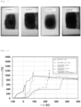
- Example Comparative Example 1 Photographs of Examples 1, 4, and 8 and Comparative Example 1 after emission of flames are shown in FIG. 7 .
- Example Comparative Example 1 2 3 4 5 6 7 8 1 Toughness (J/m 3 ) 10. 13 11. 48 12. 21 9.0 3 10. 23 10. 18 11. 54 12. 05 5.83
- Example 5 toughness is further improved when the refractory layer is formed on the upper and lower side surface parts of the side surface of the insulation sheet.
- Example 6 that the refractory layer is formed on the entirety of the side surface of the insulation sheet, whereby toughness is somewhat improved, and therefore efficiency may be somewhat improved.
- Example 7 when the refractory layer is formed on the upper and lower side surface parts of the side surface of the insulation sheet such that the thickness of the refractory layer formed on the upper side surface part is greater than the thickness of the refractory layer formed on the lower side surface part, toughness is further improved.
- Example 8 it can be seen from Example 8 that, when the refractory layer is formed on the upper and lower side surface parts of the side surface of the insulation sheet and the refractory layer is formed in a trapezoidal shape so as to wrap a part of a side surface of the cell adjacent to the upper side surface part of the side surface of the insulation sheet, toughness is effectively improved.
- Comparison Example 1 which includes no refractory layer, that fire resistance is very low.
- FIG. 7 Interior photographs of the insulation sheets of Examples 1 to 4 and 8 and Comparative Example 1 after fire resistance measurement are shown in FIG. 7 . As shown in FIG. 7 , it can be seen from the internal structures of Examples that fire resistance of the side surface of the insulation sheet is desired, advantageous or improved due to the formation of the refractory layer.
- Comparative Example 1 It can be seen from Comparative Example 1 that the side surface of the insulation sheet has low fire resistance durability while being structurally fragile. It can be seen from Examples 1, 4, and 8 that fire resistance is desired, advantageous or improved, whereby combustion does not occur, and structural stability is desired, advantageous or improved, whereby thermal insulation is also desired, advantageous or improved.
- a thermal runaway test was performed for each insulation sheet through artificial thermal runaway by heating a heating pad attached to a detonation cell (a temperature rise of 20 °C/min) under the condition that an insulation sheet is fastened between cells at a fastening pressure of 15 kN using a simple module device consisting of three prismatic cells, and thermal runaway delay time (s) was measured.
- the results of measurement are shown in Table 2 below. Temperature changes of Examples 1 and 4 and Comparative Example 1 over time are shown in FIG. 8 .
- Example Comparative Example 1 2 3 4 5 6 7 8 1 Thermal runaway delay time (s) 195 .8 187 .5 204 .2 178 .3 203 .8 224 .9 287 .1 312 .2 41.8
- thermal runaway delay effect is better. It can also be seen from FIG. 8 that, in Examples 1 and 4, the temperature rise of adjacent cells during thermal runaway is not immediate but is delayed due to the formation of the refractory layer, and in Example 1, the temperature rise is further delayed during thermal runaway.
- a battery module according to an example embodiment may inhibit propagation of heat and flames in a cell to cells adjacent thereto due to thermal runaway in the cell.
- the insulation sheet included in the battery module according to the example embodiment may have desired, advantageous or improved thermal insulation, compressibility, mechanical strength, and dimensional stability, whereby it is possible to prevent detachment of an aerogel layer due to external impact, to improve workability, and to prevent contamination of an instrument.
Landscapes
- Engineering & Computer Science (AREA)
- Chemical & Material Sciences (AREA)
- Chemical Kinetics & Catalysis (AREA)
- Electrochemistry (AREA)
- General Chemical & Material Sciences (AREA)
- Manufacturing & Machinery (AREA)
- General Engineering & Computer Science (AREA)
- Mechanical Engineering (AREA)
- Thermal Sciences (AREA)
- Physics & Mathematics (AREA)
- Aviation & Aerospace Engineering (AREA)
- Life Sciences & Earth Sciences (AREA)
- Sustainable Development (AREA)
- Sustainable Energy (AREA)
- Power Engineering (AREA)
- Transportation (AREA)
- Battery Mounting, Suspending (AREA)
- Thermal Insulation (AREA)
- Fireproofing Substances (AREA)
Applications Claiming Priority (1)
| Application Number | Priority Date | Filing Date | Title |
|---|---|---|---|
| KR1020230098057A KR20250017388A (ko) | 2023-07-27 | 2023-07-27 | 배터리 장치용 단열 조성물, 이의 제조 방법, 이를 이용하여 제조한 시트 및 이를 포함하는 배터리 모듈 |
Publications (1)
| Publication Number | Publication Date |
|---|---|
| EP4498482A1 true EP4498482A1 (fr) | 2025-01-29 |
Family
ID=91432783
Family Applications (1)
| Application Number | Title | Priority Date | Filing Date |
|---|---|---|---|
| EP24180375.8A Pending EP4498482A1 (fr) | 2023-07-27 | 2024-06-06 | Module de batterie |
Country Status (5)
| Country | Link |
|---|---|
| US (1) | US20250038308A1 (fr) |
| EP (1) | EP4498482A1 (fr) |
| JP (1) | JP7838015B2 (fr) |
| KR (1) | KR20250017388A (fr) |
| CN (1) | CN119381686A (fr) |
Families Citing this family (1)
| Publication number | Priority date | Publication date | Assignee | Title |
|---|---|---|---|---|
| KR102890939B1 (ko) * | 2025-02-27 | 2025-11-25 | 주식회사 보백씨엔에스 | 배터리 단열시트용 에어로겔 조성물, 이를 이용한 배터리 단열시트 및 이의 제조방법 |
Citations (6)
| Publication number | Priority date | Publication date | Assignee | Title |
|---|---|---|---|---|
| US1975078A (en) * | 1931-03-09 | 1934-10-02 | New England Mica Co | Mica products with inorganic binders |
| US20220069377A1 (en) * | 2020-09-02 | 2022-03-03 | Sk Innovation Co., Ltd. | Battery module comprising thermal barrier and pack |
| DE102020133450A1 (de) * | 2020-12-15 | 2022-06-15 | Bayerische Motoren Werke Aktiengesellschaft | Thermisch robuste zellanordnung und zellmodul mit einer solchen zellanordnung |
| EP4109653A1 (fr) * | 2020-10-29 | 2022-12-28 | LG Energy Solution, Ltd. | Module de batterie et bloc-batterie le comprenant |
| KR20230025973A (ko) * | 2021-08-17 | 2023-02-24 | 에스케이온 주식회사 | 열 차단막이 내장된 고전압 배터리 모듈 및 팩 |
| US11702346B2 (en) * | 2019-12-02 | 2023-07-18 | Aspen Aerogels, Inc. | Aerogel-based components and systems for electric vehicle thermal management |
Family Cites Families (4)
| Publication number | Priority date | Publication date | Assignee | Title |
|---|---|---|---|---|
| KR20170014634A (ko) | 2015-07-30 | 2017-02-08 | 현대자동차주식회사 | 단열 코팅 조성물 및 단열 코팅층 |
| JP7009534B2 (ja) | 2020-03-12 | 2022-01-25 | 住友理工株式会社 | バッテリーパック用断熱材およびバッテリーパック |
| WO2023276441A1 (fr) | 2021-06-29 | 2023-01-05 | 住友理工株式会社 | Matériau d'isolation thermique |
| JP2023055573A (ja) | 2021-10-06 | 2023-04-18 | Agc株式会社 | シリカエアロゲルの製造方法 |
-
2023
- 2023-07-27 KR KR1020230098057A patent/KR20250017388A/ko active Pending
-
2024
- 2024-05-17 JP JP2024080558A patent/JP7838015B2/ja active Active
- 2024-05-24 US US18/674,147 patent/US20250038308A1/en active Pending
- 2024-06-06 EP EP24180375.8A patent/EP4498482A1/fr active Pending
- 2024-06-28 CN CN202410855516.8A patent/CN119381686A/zh active Pending
Patent Citations (6)
| Publication number | Priority date | Publication date | Assignee | Title |
|---|---|---|---|---|
| US1975078A (en) * | 1931-03-09 | 1934-10-02 | New England Mica Co | Mica products with inorganic binders |
| US11702346B2 (en) * | 2019-12-02 | 2023-07-18 | Aspen Aerogels, Inc. | Aerogel-based components and systems for electric vehicle thermal management |
| US20220069377A1 (en) * | 2020-09-02 | 2022-03-03 | Sk Innovation Co., Ltd. | Battery module comprising thermal barrier and pack |
| EP4109653A1 (fr) * | 2020-10-29 | 2022-12-28 | LG Energy Solution, Ltd. | Module de batterie et bloc-batterie le comprenant |
| DE102020133450A1 (de) * | 2020-12-15 | 2022-06-15 | Bayerische Motoren Werke Aktiengesellschaft | Thermisch robuste zellanordnung und zellmodul mit einer solchen zellanordnung |
| KR20230025973A (ko) * | 2021-08-17 | 2023-02-24 | 에스케이온 주식회사 | 열 차단막이 내장된 고전압 배터리 모듈 및 팩 |
Also Published As
| Publication number | Publication date |
|---|---|
| KR20250017388A (ko) | 2025-02-04 |
| JP7838015B2 (ja) | 2026-03-31 |
| JP2025018923A (ja) | 2025-02-06 |
| CN119381686A (zh) | 2025-01-28 |
| US20250038308A1 (en) | 2025-01-30 |
Similar Documents
| Publication | Publication Date | Title |
|---|---|---|
| EP4498482A1 (fr) | Module de batterie | |
| EP4445999A1 (fr) | Composition d'aérogel pour feuille d'isolation de batterie, son procédé de préparation, feuille d'isolation de batterie formée à l'aide de celle-ci et son procédé de fabrication | |
| EP4512519A2 (fr) | Composition d'isolation pour dispositif de batterie, procédé de préparation de la composition d'isolation, feuille formée à l'aide de la composition d'isolation et module de batterie comprenant la feuille | |
| EP4509311A1 (fr) | Feuille d'isolation de batterie, son procédé de fabrication et module de batterie comprenant la feuille d'isolation de batterie | |
| EP4446298A1 (fr) | Feuille d'isolation de batterie et son procédé de fabrication | |
| EP4461776A1 (fr) | Composition d'aérogel pour feuille d'isolation de batterie, son procédé de fabrication, feuille d'isolation de batterie formée à l'aide de celle-ci, et module de batterie la comprenant | |
| EP4517940A1 (fr) | Feuille d'isolation pour batterie, son procédé de fabrication et module de batterie la comprenant | |
| EP4481898A1 (fr) | Module de batterie, son procédé de fabrication et bloc-batterie comprenant le module de batterie | |
| EP4512518A2 (fr) | Composition d'isolation pour dispositif de batterie, son procédé de préparation, feuille formée à l'aide de celle-ci, et module de batterie comprenant celle-ci | |
| US20250372769A1 (en) | Heat insulating sheet for rechargeable lithium battery and rechargeable lithium battery module including the same | |
| KR102843088B1 (ko) | 배터리 단열시트용 에어로겔 조성물, 이의 제조방법, 이를 이용하여 형성한 배터리 단열시트 및 이의 제조방법 | |
| US20250385340A1 (en) | Heat insulating sheet for rechargeable lithium battery and rechargeable lithium battery module including the same | |
| US20250337055A1 (en) | Heat insulation sheet for rechargeable lithium battery and rechargeable lithium battery module including the same | |
| KR20250158849A (ko) | 리튬 이차 전지용 단열 시트 및 이를 포함하는 리튬 이차 전지 모듈 | |
| KR20250157840A (ko) | 리튬 이차 전지용 단열 시트 및 이를 포함하는 리튬 이차 전지 모듈 | |
| KR20250158140A (ko) | 리튬 이차 전지용 단열 시트 및 이를 포함하는 리튬 이차 전지 모듈 | |
| KR20250158291A (ko) | 리튬 이차 전지용 단열 시트 및 이를 포함하는 리튬 이차 전지 모듈 |
Legal Events
| Date | Code | Title | Description |
|---|---|---|---|
| PUAI | Public reference made under article 153(3) epc to a published international application that has entered the european phase |
Free format text: ORIGINAL CODE: 0009012 |
|
| STAA | Information on the status of an ep patent application or granted ep patent |
Free format text: STATUS: REQUEST FOR EXAMINATION WAS MADE |
|
| 17P | Request for examination filed |
Effective date: 20240606 |
|
| AK | Designated contracting states |
Kind code of ref document: A1 Designated state(s): AL AT BE BG CH CY CZ DE DK EE ES FI FR GB GR HR HU IE IS IT LI LT LU LV MC ME MK MT NL NO PL PT RO RS SE SI SK SM TR |