EP4498521A1 - Phasengesteuerte gruppenantenneneinheit, phasengesteuerte gruppenantenne und radarsystem - Google Patents
Phasengesteuerte gruppenantenneneinheit, phasengesteuerte gruppenantenne und radarsystem Download PDFInfo
- Publication number
- EP4498521A1 EP4498521A1 EP24182265.9A EP24182265A EP4498521A1 EP 4498521 A1 EP4498521 A1 EP 4498521A1 EP 24182265 A EP24182265 A EP 24182265A EP 4498521 A1 EP4498521 A1 EP 4498521A1
- Authority
- EP
- European Patent Office
- Prior art keywords
- phased array
- array antenna
- radiator
- antenna unit
- patch
- Prior art date
- Legal status (The legal status is an assumption and is not a legal conclusion. Google has not performed a legal analysis and makes no representation as to the accuracy of the status listed.)
- Pending
Links
Images





Classifications
-
- H—ELECTRICITY
- H01—ELECTRIC ELEMENTS
- H01Q—ANTENNAS, i.e. RADIO AERIALS
- H01Q1/00—Details of, or arrangements associated with, antennas
- H01Q1/36—Structural form of radiating elements, e.g. cone, spiral, umbrella; Particular materials used therewith
- H01Q1/38—Structural form of radiating elements, e.g. cone, spiral, umbrella; Particular materials used therewith formed by a conductive layer on an insulating support
-
- H—ELECTRICITY
- H01—ELECTRIC ELEMENTS
- H01Q—ANTENNAS, i.e. RADIO AERIALS
- H01Q1/00—Details of, or arrangements associated with, antennas
- H01Q1/52—Means for reducing coupling between antennas; Means for reducing coupling between an antenna and another structure
- H01Q1/521—Means for reducing coupling between antennas; Means for reducing coupling between an antenna and another structure reducing the coupling between adjacent antennas
- H01Q1/523—Means for reducing coupling between antennas; Means for reducing coupling between an antenna and another structure reducing the coupling between adjacent antennas between antennas of an array
-
- H—ELECTRICITY
- H01—ELECTRIC ELEMENTS
- H01Q—ANTENNAS, i.e. RADIO AERIALS
- H01Q3/00—Arrangements for changing or varying the orientation or the shape of the directional pattern of the waves radiated from an antenna or antenna system
- H01Q3/26—Arrangements for changing or varying the orientation or the shape of the directional pattern of the waves radiated from an antenna or antenna system varying the relative phase or relative amplitude of energisation between two or more active radiating elements; varying the distribution of energy across a radiating aperture
- H01Q3/30—Arrangements for changing or varying the orientation or the shape of the directional pattern of the waves radiated from an antenna or antenna system varying the relative phase or relative amplitude of energisation between two or more active radiating elements; varying the distribution of energy across a radiating aperture varying the relative phase between the radiating elements of an array
- H01Q3/34—Arrangements for changing or varying the orientation or the shape of the directional pattern of the waves radiated from an antenna or antenna system varying the relative phase or relative amplitude of energisation between two or more active radiating elements; varying the distribution of energy across a radiating aperture varying the relative phase between the radiating elements of an array by electrical means
- H01Q3/36—Arrangements for changing or varying the orientation or the shape of the directional pattern of the waves radiated from an antenna or antenna system varying the relative phase or relative amplitude of energisation between two or more active radiating elements; varying the distribution of energy across a radiating aperture varying the relative phase between the radiating elements of an array by electrical means with variable phase-shifters
-
- G—PHYSICS
- G01—MEASURING; TESTING
- G01S—RADIO DIRECTION-FINDING; RADIO NAVIGATION; DETERMINING DISTANCE OR VELOCITY BY USE OF RADIO WAVES; LOCATING OR PRESENCE-DETECTING BY USE OF THE REFLECTION OR RERADIATION OF RADIO WAVES; ANALOGOUS ARRANGEMENTS USING OTHER WAVES
- G01S7/00—Details of systems according to groups G01S13/00, G01S15/00, G01S17/00
- G01S7/02—Details of systems according to groups G01S13/00, G01S15/00, G01S17/00 of systems according to group G01S13/00
- G01S7/03—Details of HF subsystems specially adapted therefor, e.g. common to transmitter and receiver
-
- H—ELECTRICITY
- H01—ELECTRIC ELEMENTS
- H01Q—ANTENNAS, i.e. RADIO AERIALS
- H01Q1/00—Details of, or arrangements associated with, antennas
- H01Q1/52—Means for reducing coupling between antennas; Means for reducing coupling between an antenna and another structure
-
- H—ELECTRICITY
- H01—ELECTRIC ELEMENTS
- H01Q—ANTENNAS, i.e. RADIO AERIALS
- H01Q21/00—Antenna arrays or systems
-
- H—ELECTRICITY
- H01—ELECTRIC ELEMENTS
- H01Q—ANTENNAS, i.e. RADIO AERIALS
- H01Q21/00—Antenna arrays or systems
- H01Q21/06—Arrays of individually energised antenna units similarly polarised and spaced apart
- H01Q21/061—Two dimensional planar arrays
- H01Q21/065—Patch antenna array
-
- H—ELECTRICITY
- H01—ELECTRIC ELEMENTS
- H01Q—ANTENNAS, i.e. RADIO AERIALS
- H01Q21/00—Antenna arrays or systems
- H01Q21/24—Combinations of antenna units polarised in different directions for transmitting or receiving circularly and elliptically polarised waves or waves linearly polarised in any direction
-
- H—ELECTRICITY
- H01—ELECTRIC ELEMENTS
- H01Q—ANTENNAS, i.e. RADIO AERIALS
- H01Q9/00—Electrically-short antennas having dimensions not more than twice the operating wavelength and consisting of conductive active radiating elements
- H01Q9/04—Resonant antennas
- H01Q9/0407—Substantially flat resonant element parallel to ground plane, e.g. patch antenna
-
- H—ELECTRICITY
- H01—ELECTRIC ELEMENTS
- H01Q—ANTENNAS, i.e. RADIO AERIALS
- H01Q9/00—Electrically-short antennas having dimensions not more than twice the operating wavelength and consisting of conductive active radiating elements
- H01Q9/04—Resonant antennas
- H01Q9/0407—Substantially flat resonant element parallel to ground plane, e.g. patch antenna
- H01Q9/045—Substantially flat resonant element parallel to ground plane, e.g. patch antenna with particular feeding means
- H01Q9/0457—Substantially flat resonant element parallel to ground plane, e.g. patch antenna with particular feeding means electromagnetically coupled to the feed line
Definitions
- the present disclosure relates to the field of terminal technology, and in particular, to a phased array antenna unit, a phased array antenna and a radar system.
- phased array antenna When the phased array antenna is in operation, there is a certain amount of electromagnetic energy coupling between adjacent antenna units. That is, there will be a mutual coupling effect between adjacent antenna units. The existence of the mutual coupling effect will change the impedance characteristic of the antenna unit, affecting the beam shape for the phased array antenna.
- the present disclosure provides a phased array antenna unit, a phased array antenna and a radar system, in order to address deficiencies in the related art.
- a phased array antenna unit including: a first dielectric substrate; a radiator; and a plurality of decoupling metal patches, where the plurality of decoupling metal patches and the radiator are arranged on a same surface of the first dielectric substrate, and a side-by-side direction of the plurality of decoupling metal patches is perpendicular to a direction of an electric field intensity when the radiator is operating, and the radiator is arranged between any two adjacent decoupling metal patches.
- the direction of the electric field intensity when the radiator is operating includes a first electric field direction and a second electric field direction, and the first electric field direction is perpendicular to the second electric field direction;
- the plurality of decoupling metal patches includes a plurality of first decoupling metal patches arranged side by side along the first electric field direction, and a plurality of second decoupling metal patches arranged side by side along the second electric field direction; and the radiator is located between two adjacent first decoupling metal patches, and the radiator is also located between two adjacent second decoupling metal patches.
- the decoupling metal patch includes a strip patch, and a length direction of the strip patch is perpendicular to a side-by-side direction of a plurality of strip patches, and a difference between length and width of the strip patch is greater than or equal to a set threshold.
- one or more strip patches are provided on a same side of the radiator.
- lengths of the plurality of strip patches are equal, or the lengths of the plurality of strips are in an arithmetic sequence, and a strip patch with smallest length is placed close to the radiator among a plurality of strip patches provided on the same side of the radiator.
- the decoupling metal patch includes an isosceles trapezoidal patch.
- an upper bottom of the isosceles trapezoidal patch is set toward the radiator.
- the phased array antenna unit further includes a second dielectric substrate, a feed layer, a via layer, a first feed probe and a second feed probe; where the second dielectric substrate is disposed below the first dielectric substrate, the first feed probe is disposed on a surface of the second dielectric substrate facing the first dielectric substrate, and the first feed probe is coupled to the radiator for power feeding; and the feed layer is disposed below the second dielectric substrate, the via layer is disposed between the second dielectric substrate and the feed layer, and the second feed probe passes through the via layer and is electrically connected to the feed layer, and the second feed probe also passes through the second dielectric substrate and is electrically connected to the first feed probe.
- the radiator is a rectangular radiator, and the decoupling metal patch is provided on each side of the rectangular radiator.
- phased array antenna including a plurality of phased array antenna units according to any one of the above embodiments, where adjacent radiators share a same decoupling patch.
- a radar system including a phased array antenna according to any one of the above embodiments.
- the present invention provides a phased array antenna unit.
- the decoupling metal patches side by side along the direction perpendicular to the direction of the electric field intensity on both sides of the radiator, the mutual coupling effect among the radiators is suppressed with the help of the radiated field generated by the decoupling metal patches.
- the decoupling effect is good, and performance indexes such as the low profiling and the lightweight of the phased array antenna are satisfied.
- first, second, third, etc. may be used in the present disclosure to describe various information, the information should not be limited to these terms. These terms are only used to distinguish information of the same type from each other.
- first information may also be called second information, and similarly, the second information may also be called first information.
- word “if” as used herein may be interpreted as "when” or “at” or “in response to determining.”
- the present invention provides a phased array antenna unit.
- a decoupling metal patch outside the radiator of the antenna unit, and by reasonably setting the position of the decoupling metal patch, the radiation field generated by the decoupling metal patch is used to suppress the mutual coupling effect between radiators, which has good decoupling effect, and meets the performance indicators of the phased array antenna such as low profile and lightweight.
- FIG. 1 is a schematic top view of a phased array antenna unit 100 according to an embodiment.
- the phased array antenna unit 100 includes a first dielectric substrate 1, a radiator 2 and a plurality of decoupling metal patches 3.
- the plurality of decoupling metal patches 3 and the radiator 2 are arranged on the same surface of the first dielectric substrate 1.
- the plurality of decoupling metal patches 3 are arranged side by side in a direction perpendicular to the direction of the electric field intensity when the radiator 2 is operating.
- the radiator 2 is arranged between any two adjacent decoupling metal patches 3.
- the plurality of decoupling metal patches 3 can be arranged uniformly on both sides of the radiator 2, or they can also be arranged non-uniformly on both sides of the decoupling metal patch 3.
- the side-by-side direction of the plurality of decoupling metal patches 3 is designed to be perpendicular to the direction of the electric field intensity when the radiator 2 is operating, and then the radiator 2 is arranged between any two adjacent decoupling metal patches 3. In this way, by limiting the positions of the decoupling metal patches 3, the effect of the decoupling metal patches 3 in suppressing the mutual coupling effect can be greatly improved.
- Active S 11 is the active reflection coefficient of the first antenna unit
- Active VSWR is the active standing wave ratio
- ⁇ i 1 is the phase difference of each other antenna unit relative to the first antenna unit at the scanning angle ⁇ 0
- S 1 i is the transmission coefficient between the i-th antenna unit and the first antenna unit.
- the active reflection coefficient and active standing wave ratio it is known that, in order to reduce the mutual coupling effect between adjacent antenna units, it is necessary to reduce the transmission coefficient between antenna units, that is, to reduce the active reflection coefficient. Then, the decrease in reflection coefficient will cause the active standing wave ratio to decrease accordingly. Therefore, when the active standing wave ratio decreases, the mutual coupling effect between array elements can be reduced.
- the decoupling metal patch 3 in FIG. 1 is an isosceles trapezoidal patch and the antenna unit is a doubly fed port, and the upper bottom of the isosceles trapezoidal patch is set towards the radiator 2.
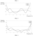
- the standing wave characteristic curves of the two ports of the phased array antenna unit 100 in the case of side radiation.
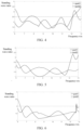
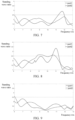
- the E-plane and H-plane scans are analyzed respectively, and standing wave characteristic curves as shown in FIG. 3, FIG. 4 and FIG. 5 are obtained, which are the standing wave characteristic curves of the two ports at the scanning angle of E plane 30°, E plane 45°, and H plane 30°, respectively.
- the standing wave characteristic curves of the two ports in the case of side radiation as shown in FIG. 6 and the standing wave characteristic curves at the same E-plane and H-plane scanning angles as shown in FIG. 7 to FIG. 9 , which are added by the inventor, are obtained by simulation.
- the horizontal coordinate is labeled as frequency
- the vertical coordinate is labeled as active standing wave ratio.
- the solid line represents the change curve of the active standing wave ratio versus frequency of the first port at the same scanning angle.
- the dotted line represents the change curve of the active standing wave ratio versus frequency of the second port at the same scanning angle.
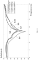
- FIG. 10 shows the isolation curves between the two ports without isosceles trapezoidal patches at various scanning angles.
- the curve S 1 is the isolation curve between the two ports in the case of side radiation.
- the curve S2 is the isolation curve between the two ports at the scanning angle of E plane 30°.
- the curve S3 is the isolation curve between the two ports at the scanning angle of E plane 45°.
- the curve S4 is the isolation curve between the two ports at the scanning angle of H plane 30°.
- the curve S5 is the isolation curve between the two ports at the scanning angle of H plane 45°.
- FIG. 11 shows the isolation curves between the two ports when adding isosceles trapezoidal patches.
- the curve S6 is the isolation curve between the two ports in the case of side radiation.
- the curve S7 is the isolation curve between the two ports at the scanning angle of E plane 30°.
- the curve S8 is the isolation curve between the two ports at the scanning angle of E plane 45°.
- the curve S9 is the isolation curve between the two ports at the scanning angle of H plane 30°.
- the curve S10 is the isolation curve between the two ports at the scanning angle of H plane 45°.
- the horizontal coordinate is frequency and the vertical coordinate is isolation.
- the antenna unit with the isosceles trapezoidal patch is applied to the 7 ⁇ 7 phased array antenna for simulation, and three frequency points of 7GHz, 9.6GHz and 12GHz are selected.
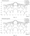
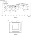
- the radiation patterns of the dual-port phased array antenna in the case of side radiation and at various scanning angles, as shown in FIG. 12, FIG. 13 , FIG. 14, FIG. 15 , FIG. 16 , FIG. 17 , FIG. 18 and FIG. 19 , are further obtained.
- FIG. 12 is the radiation pattern of the phased array antenna with the first port in side radiation.
- FIG. 13 is the radiation pattern of the phased array antenna with the second port in side radiation.
- FIG. 14 is the radiation pattern of the phased array antenna with the first port at the scanning angle of E plane 30°.
- FIG. 15 is the radiation pattern of the phased array antenna with the second port at the scanning angle of E plane 30°.
- FIG. 16 is the radiation pattern of the phased array antenna with the first port at the scanning angle of E plane 45°.
- FIG. 17 is the radiation pattern of the phased array antenna with the second port at the scanning angle of E plane 45°.
- FIG. 18 is radiation pattern of the phased array antenna with the first port at the scan angle of H plane 30°.
- FIG. 19 is the radiation pattern of the phased array antenna with the second port at the scanning angle of H plane 30°.
- the solid lines are the main polarization patterns
- the dotted lines are the cross-polarization patterns. Observing the phased array antenna pattern in FIG. 12 to FIG. 19 , it can be seen that in the case of side radiation and at respective scanning angles, the main polarization gain is greater than the cross-polarization gain, which meets the design requirement of the phased array antenna.
- the radiator 2 has two directions of the electric field intensity. That is, the electric field direction of the electromagnetic wave of the radiator 2 can include a first electric field direction and a second electric field direction.
- the first electric field direction is a direction of the electric field intensity during vertical polarization, and the direction of the electric field intensity is parallel to the ground.
- the second electric field direction is a direction of the electric field intensity during horizontal polarization, and the direction of the electric field intensity is perpendicular to the ground. That is, the first electric field direction is the horizontal direction with the ground in FIG. 1 , the second electric field direction is the vertical direction in FIG. 1 .
- the first electric field direction is perpendicular to the second electric field direction.
- the plurality of decoupling metal patches 3 may include a first decoupling metal patch 3A arranged parallel to the first electric field direction, and a second decoupling metal patch 3B arranged parallel to the second electric field direction.
- the radiator 2 may be arranged between two adjacent first decoupling metal patches 3A and between two adjacent second decoupling metal patches 3B. Therefore, when the radiator 2 is a dual-polarized antenna, the decoupling metal patches 3 can be arranged in directions perpendicular to various polarization direction to enhance the decoupling effect.
- the radiator 2 can be a single-polarized radiator. That is, there is only one direction of the electric field intensity when the radiator 2 is operating, such as the horizontal direction or the vertical direction in FIG. 1 .
- the decoupling metal patches 3 can be set only on the horizontal sides of the radiator 2, or the decoupling metal patches 3 can be set only on the vertical sides of the radiator 2, which can be specifically determined according to the polarity direction of the radiator 2.
- the radiator 2 is a single-polarized radiator, since the phased array antenna unit 100 needs to be used in a phased array antenna later, multiple decoupling metal patches 3 can be arranged side by side in a direction parallel to the electric field direction of the electromagnetic wave to enhance the decoupling effect. For example, assuming that the radiator 2 is a rectangular radiator, a decoupling metal patch 3 can be provided on each side of the rectangular radiator.
- the decoupling metal patch 3 is an isosceles trapezoidal patch as an example.
- the decoupling metal patch 3 may include a strip patch.
- the length direction of the strip patch is perpendicular to the side-by-side direction of multiple strip patches, and the difference between the length and width of the strip patch is greater than or equal to the set threshold.
- the arrangement can refer to the arrangement of the isosceles trapezoidal patch in the previous embodiment.
- a strip patch can be provided on each side of the radiator 2.
- FIG. 20 when the radiator 2 is a dual-polarized radiator, a strip patch can be provided on each side of the radiator 2. Or, as shown in FIG.
- corresponding strip patches can be set only on the periphery of a set of opposite sides of the radiator 2.
- the side-by-side direction of the strip patches is perpendicular to the direction of the electric field intensity when the radiator 2 is operating, which will not be repeated here.
- strip patches can also be arranged on each side of the radiator 2, which is not limited by the present disclosure.
- a single strip patch is arranged on each side of the radiator 2 as an example.
- multiple strip patches can also be arranged on each side of the radiator 2.
- the lengths of the plurality of strip patches can be equal.
- the lengths of the plurality of strip patches are different.
- the lengths of the plurality of strip patches can be set in an arithmetic sequence, and the strip patch with the smallest length is arranged close to the radiator 2 among the plurality of strip patches arranged on the same side of the radiator 2.
- the lengths of the plurality of the strip patches are set in an arithmetic sequence, and the decoupling effect is equivalent to that of isosceles trapezoidal patches.
- the lengths of the plurality of the strip patches being set in an arithmetic sequence can be considered to be another expression of isosceles trapezoidal patches.
- the isosceles trapezoidal patch is designed for continuity of current.
- the phased array antenna unit 100 may also include a second dielectric substrate 4, a feed layer 5, a via layer 6, a first feed probe 7 and a second feed probe 8.
- the second dielectric substrate 4 is disposed below the first dielectric substrate 1.
- the feed layer 5 is disposed below the second dielectric substrate 4.
- the via layer 6 is disposed between the second dielectric substrate 4 and the feed layer 5.
- the first feed probe 7 is disposed on the surface of the second dielectric substrate 4 facing the first dielectric substrate 1, and the radiator 2 is coupled and fed through the first feed probe 7.
- the second feed probe 8 passes through the via layer 6 and the second dielectric substrate 4, and is connected to the feed layer 5 and the first feed probe 7 respectively, so that the signal transmission between the feed layer 5 and the radiator 2 can be realized.
- the feed layer 5 may include structures such as radio frequency devices and required dielectric substrate layers.
- the present invention also provides a phased array antenna.
- the phased array antenna may include a plurality of phased array antenna units described in any of the above embodiments.
- the plurality of phased array antenna units are arranged in a regular array, and the adjacent radiators 2 can share the same decoupling patch.
- the present disclosure also provides a radar system.
- the radar system may include the phased array antenna described in the above embodiments.
- the radar system may be applied to satellites, fighter aircraft, and other apparatus.
Landscapes
- Engineering & Computer Science (AREA)
- Physics & Mathematics (AREA)
- Computer Networks & Wireless Communication (AREA)
- General Physics & Mathematics (AREA)
- Radar, Positioning & Navigation (AREA)
- Remote Sensing (AREA)
- Electromagnetism (AREA)
- Variable-Direction Aerials And Aerial Arrays (AREA)
Applications Claiming Priority (1)
| Application Number | Priority Date | Filing Date | Title |
|---|---|---|---|
| CN202310912815.6A CN116706531A (zh) | 2023-07-24 | 2023-07-24 | 相控阵天线单元、相控阵天线和雷达系统 |
Publications (1)
| Publication Number | Publication Date |
|---|---|
| EP4498521A1 true EP4498521A1 (de) | 2025-01-29 |
Family
ID=87824148
Family Applications (1)
| Application Number | Title | Priority Date | Filing Date |
|---|---|---|---|
| EP24182265.9A Pending EP4498521A1 (de) | 2023-07-24 | 2024-06-14 | Phasengesteuerte gruppenantenneneinheit, phasengesteuerte gruppenantenne und radarsystem |
Country Status (3)
| Country | Link |
|---|---|
| US (1) | US20250038406A1 (de) |
| EP (1) | EP4498521A1 (de) |
| CN (1) | CN116706531A (de) |
Citations (4)
| Publication number | Priority date | Publication date | Assignee | Title |
|---|---|---|---|---|
| US20210313703A1 (en) * | 2018-05-09 | 2021-10-07 | Huawei Technologies Co., Ltd. | Millimeter-Wave Antenna Array Element, Array Antenna, and Communications Product |
| CN112072294B (zh) * | 2020-08-28 | 2022-01-25 | 电子科技大学 | 一种宽带低剖面高隔离度双圆极化二维宽角扫描稀疏阵列 |
| US20230039854A1 (en) * | 2021-08-05 | 2023-02-09 | South China University Of Technology | Shared-Aperture Dual-Band Dual-Polarized Antenna Array and Communication Equipment |
| US20230101577A1 (en) * | 2020-06-08 | 2023-03-30 | Guangdong Oppo Mobile Telecommunications Corp, Ltd. | Millimeter wave antenna module and electronic device |
Family Cites Families (3)
| Publication number | Priority date | Publication date | Assignee | Title |
|---|---|---|---|---|
| CN111769358B (zh) * | 2020-07-30 | 2022-07-12 | 西安电子科技大学 | 基于超表面的低剖面宽带方向图分集天线 |
| CN112838361B (zh) * | 2020-12-30 | 2021-11-23 | 华南理工大学 | 耦合抵消路径枝节及基于其的高隔离毫米波相控阵列天线 |
| CN113451760B (zh) * | 2021-07-28 | 2025-04-25 | 福州大学 | 一种应用于5g移动通信的毫米波宽带mimo天线 |
-
2023
- 2023-07-24 CN CN202310912815.6A patent/CN116706531A/zh active Pending
-
2024
- 2024-04-30 US US18/651,641 patent/US20250038406A1/en active Pending
- 2024-06-14 EP EP24182265.9A patent/EP4498521A1/de active Pending
Patent Citations (4)
| Publication number | Priority date | Publication date | Assignee | Title |
|---|---|---|---|---|
| US20210313703A1 (en) * | 2018-05-09 | 2021-10-07 | Huawei Technologies Co., Ltd. | Millimeter-Wave Antenna Array Element, Array Antenna, and Communications Product |
| US20230101577A1 (en) * | 2020-06-08 | 2023-03-30 | Guangdong Oppo Mobile Telecommunications Corp, Ltd. | Millimeter wave antenna module and electronic device |
| CN112072294B (zh) * | 2020-08-28 | 2022-01-25 | 电子科技大学 | 一种宽带低剖面高隔离度双圆极化二维宽角扫描稀疏阵列 |
| US20230039854A1 (en) * | 2021-08-05 | 2023-02-09 | South China University Of Technology | Shared-Aperture Dual-Band Dual-Polarized Antenna Array and Communication Equipment |
Also Published As
| Publication number | Publication date |
|---|---|
| CN116706531A (zh) | 2023-09-05 |
| US20250038406A1 (en) | 2025-01-30 |
Similar Documents
| Publication | Publication Date | Title |
|---|---|---|
| KR102063222B1 (ko) | 안테나 어레이에서의 상호 결합을 감소시키기 위한 장치 및 방법 | |
| EP0891643B1 (de) | Dualpolarisations-gruppenantenne mit sehr niedriger kreuzpolarisation und kleinen seitenkeulen | |
| Shafai et al. | Dual-band dual-polarized perforated microstrip antennas for SAR applications | |
| US6195063B1 (en) | Dual-polarized antenna system | |
| KR101687504B1 (ko) | 집적된 밸룬을 가진 이중 분극 전류 루프 라디에이터 | |
| US7994985B2 (en) | Isolation enhancement technique for dual-polarized probe-fed patch antenna | |
| CN105226400A (zh) | 一种宽带双极化相控阵天线及全极化波束形成方法 | |
| CN113871865A (zh) | 一种低剖面宽带宽角二维扫描双极化相控阵天线及应用 | |
| CN203596414U (zh) | 渐变缝隙天线及其相控阵天线 | |
| Benny et al. | Aperture fed microstrip dual polarization wide scan phased array antenna with mutual coupling reduction | |
| CN113285215B (zh) | 一种宽带双极化波导缝隙天线单元 | |
| Chen et al. | A cross-polarization suppressed probe-fed patch antenna and its applications to wide-angle beam-scanning arrays | |
| CN110165406A (zh) | 一种方向图可重构天线单元及相控阵 | |
| CN209822857U (zh) | 一种新型紧馈型宽带双极化蝶形振子 | |
| EP4498521A1 (de) | Phasengesteuerte gruppenantenneneinheit, phasengesteuerte gruppenantenne und radarsystem | |
| US12476359B2 (en) | Phased array antenna with high impedance surface | |
| Yang et al. | Differentially-fed dual-polarized 2D multibeam antenna array for millimeter-wave applications | |
| Lee et al. | Multiparametric design of an all-metal, broadband, slant dual-polarized Vivaldi array antenna | |
| Zhao et al. | Microstrip phased array antenna with small element space for 5G millimeter-wave applications | |
| CN117013245A (zh) | 一种基于双模贴片单元的毫米波宽角扫描相控阵 | |
| Liu et al. | An X-band dual-polarized microstrip phased array antenna with wide-angle scanning | |
| CN113964489A (zh) | 基于弯折形缝隙的宽角扫描相控阵天线 | |
| Oikonomopoulos-Zachos et al. | A MIMO antenna array with shaped beam in waveguide technology for WiFi base stations | |
| CN115296047B (zh) | 紧耦合圆极化共口径天线 | |
| Li et al. | A wide beam dipole antenna in the E-and H-plane with a novel structure |
Legal Events
| Date | Code | Title | Description |
|---|---|---|---|
| PUAI | Public reference made under article 153(3) epc to a published international application that has entered the european phase |
Free format text: ORIGINAL CODE: 0009012 |
|
| STAA | Information on the status of an ep patent application or granted ep patent |
Free format text: STATUS: THE APPLICATION HAS BEEN PUBLISHED |
|
| AK | Designated contracting states |
Kind code of ref document: A1 Designated state(s): AL AT BE BG CH CY CZ DE DK EE ES FI FR GB GR HR HU IE IS IT LI LT LU LV MC ME MK MT NL NO PL PT RO RS SE SI SK SM TR |
|
| STAA | Information on the status of an ep patent application or granted ep patent |
Free format text: STATUS: REQUEST FOR EXAMINATION WAS MADE |
|
| 17P | Request for examination filed |
Effective date: 20250728 |