EP4498535A1 - Alimentation électrique à fiches interchangeables - Google Patents
Alimentation électrique à fiches interchangeables Download PDFInfo
- Publication number
- EP4498535A1 EP4498535A1 EP23197599.6A EP23197599A EP4498535A1 EP 4498535 A1 EP4498535 A1 EP 4498535A1 EP 23197599 A EP23197599 A EP 23197599A EP 4498535 A1 EP4498535 A1 EP 4498535A1
- Authority
- EP
- European Patent Office
- Prior art keywords
- plug
- power supply
- unit
- power
- interchangeable
- Prior art date
- Legal status (The legal status is an assumption and is not a legal conclusion. Google has not performed a legal analysis and makes no representation as to the accuracy of the status listed.)
- Pending
Links
- 239000002184 metal Substances 0.000 claims abstract description 38
- 229910052751 metal Inorganic materials 0.000 claims abstract description 38
- 230000003993 interaction Effects 0.000 claims abstract description 16
- 238000000465 moulding Methods 0.000 claims description 2
- 230000002708 enhancing effect Effects 0.000 claims 1
- 238000006243 chemical reaction Methods 0.000 abstract description 9
- 238000010586 diagram Methods 0.000 description 6
- 238000004880 explosion Methods 0.000 description 4
- 235000014676 Phragmites communis Nutrition 0.000 description 3
- 150000002739 metals Chemical class 0.000 description 2
- 244000089486 Phragmites australis subsp australis Species 0.000 description 1
- 230000004308 accommodation Effects 0.000 description 1
- 238000005516 engineering process Methods 0.000 description 1
- 238000012986 modification Methods 0.000 description 1
- 230000004048 modification Effects 0.000 description 1
- 238000007789 sealing Methods 0.000 description 1
Images




Classifications
-
- H—ELECTRICITY
- H01—ELECTRIC ELEMENTS
- H01R—ELECTRICALLY-CONDUCTIVE CONNECTIONS; STRUCTURAL ASSOCIATIONS OF A PLURALITY OF MUTUALLY-INSULATED ELECTRICAL CONNECTING ELEMENTS; COUPLING DEVICES; CURRENT COLLECTORS
- H01R31/00—Coupling parts supported only by co-operation with counterpart
- H01R31/06—Intermediate parts for linking two coupling parts, e.g. adapter
-
- H—ELECTRICITY
- H01—ELECTRIC ELEMENTS
- H01R—ELECTRICALLY-CONDUCTIVE CONNECTIONS; STRUCTURAL ASSOCIATIONS OF A PLURALITY OF MUTUALLY-INSULATED ELECTRICAL CONNECTING ELEMENTS; COUPLING DEVICES; CURRENT COLLECTORS
- H01R27/00—Coupling parts adapted for co-operation with two or more dissimilar counterparts
-
- H—ELECTRICITY
- H01—ELECTRIC ELEMENTS
- H01R—ELECTRICALLY-CONDUCTIVE CONNECTIONS; STRUCTURAL ASSOCIATIONS OF A PLURALITY OF MUTUALLY-INSULATED ELECTRICAL CONNECTING ELEMENTS; COUPLING DEVICES; CURRENT COLLECTORS
- H01R13/00—Details of coupling devices of the kinds covered by groups H01R12/70 or H01R24/00 - H01R33/00
- H01R13/46—Bases; Cases
- H01R13/52—Dustproof, splashproof, drip-proof, waterproof, or flameproof cases
- H01R13/5202—Sealing means between parts of housing or between housing part and a wall, e.g. sealing rings
-
- H—ELECTRICITY
- H01—ELECTRIC ELEMENTS
- H01R—ELECTRICALLY-CONDUCTIVE CONNECTIONS; STRUCTURAL ASSOCIATIONS OF A PLURALITY OF MUTUALLY-INSULATED ELECTRICAL CONNECTING ELEMENTS; COUPLING DEVICES; CURRENT COLLECTORS
- H01R13/00—Details of coupling devices of the kinds covered by groups H01R12/70 or H01R24/00 - H01R33/00
- H01R13/02—Contact members
- H01R13/20—Pins, blades, or sockets shaped, or provided with separate member, to retain co-operating parts together
-
- H—ELECTRICITY
- H01—ELECTRIC ELEMENTS
- H01R—ELECTRICALLY-CONDUCTIVE CONNECTIONS; STRUCTURAL ASSOCIATIONS OF A PLURALITY OF MUTUALLY-INSULATED ELECTRICAL CONNECTING ELEMENTS; COUPLING DEVICES; CURRENT COLLECTORS
- H01R13/00—Details of coupling devices of the kinds covered by groups H01R12/70 or H01R24/00 - H01R33/00
- H01R13/46—Bases; Cases
- H01R13/502—Bases; Cases composed of different pieces
-
- H—ELECTRICITY
- H01—ELECTRIC ELEMENTS
- H01R—ELECTRICALLY-CONDUCTIVE CONNECTIONS; STRUCTURAL ASSOCIATIONS OF A PLURALITY OF MUTUALLY-INSULATED ELECTRICAL CONNECTING ELEMENTS; COUPLING DEVICES; CURRENT COLLECTORS
- H01R13/00—Details of coupling devices of the kinds covered by groups H01R12/70 or H01R24/00 - H01R33/00
- H01R13/62—Means for facilitating engagement or disengagement of coupling parts or for holding them in engagement
- H01R13/629—Additional means for facilitating engagement or disengagement of coupling parts, e.g. aligning or guiding means, levers, gas pressure electrical locking indicators, manufacturing tolerances
-
- H—ELECTRICITY
- H01—ELECTRIC ELEMENTS
- H01R—ELECTRICALLY-CONDUCTIVE CONNECTIONS; STRUCTURAL ASSOCIATIONS OF A PLURALITY OF MUTUALLY-INSULATED ELECTRICAL CONNECTING ELEMENTS; COUPLING DEVICES; CURRENT COLLECTORS
- H01R13/00—Details of coupling devices of the kinds covered by groups H01R12/70 or H01R24/00 - H01R33/00
- H01R13/62—Means for facilitating engagement or disengagement of coupling parts or for holding them in engagement
- H01R13/639—Additional means for holding or locking coupling parts together, after engagement, e.g. separate keylock, retainer strap
-
- H—ELECTRICITY
- H01—ELECTRIC ELEMENTS
- H01R—ELECTRICALLY-CONDUCTIVE CONNECTIONS; STRUCTURAL ASSOCIATIONS OF A PLURALITY OF MUTUALLY-INSULATED ELECTRICAL CONNECTING ELEMENTS; COUPLING DEVICES; CURRENT COLLECTORS
- H01R13/00—Details of coupling devices of the kinds covered by groups H01R12/70 or H01R24/00 - H01R33/00
- H01R13/02—Contact members
- H01R13/04—Pins or blades for co-operation with sockets
-
- H—ELECTRICITY
- H01—ELECTRIC ELEMENTS
- H01R—ELECTRICALLY-CONDUCTIVE CONNECTIONS; STRUCTURAL ASSOCIATIONS OF A PLURALITY OF MUTUALLY-INSULATED ELECTRICAL CONNECTING ELEMENTS; COUPLING DEVICES; CURRENT COLLECTORS
- H01R13/00—Details of coupling devices of the kinds covered by groups H01R12/70 or H01R24/00 - H01R33/00
- H01R13/02—Contact members
- H01R13/10—Sockets for co-operation with pins or blades
- H01R13/11—Resilient sockets
- H01R13/112—Resilient sockets forked sockets having two legs
-
- H—ELECTRICITY
- H01—ELECTRIC ELEMENTS
- H01R—ELECTRICALLY-CONDUCTIVE CONNECTIONS; STRUCTURAL ASSOCIATIONS OF A PLURALITY OF MUTUALLY-INSULATED ELECTRICAL CONNECTING ELEMENTS; COUPLING DEVICES; CURRENT COLLECTORS
- H01R13/00—Details of coupling devices of the kinds covered by groups H01R12/70 or H01R24/00 - H01R33/00
- H01R13/02—Contact members
- H01R13/10—Sockets for co-operation with pins or blades
- H01R13/11—Resilient sockets
- H01R13/113—Resilient sockets co-operating with pins or blades having a rectangular transverse section
-
- H—ELECTRICITY
- H01—ELECTRIC ELEMENTS
- H01R—ELECTRICALLY-CONDUCTIVE CONNECTIONS; STRUCTURAL ASSOCIATIONS OF A PLURALITY OF MUTUALLY-INSULATED ELECTRICAL CONNECTING ELEMENTS; COUPLING DEVICES; CURRENT COLLECTORS
- H01R13/00—Details of coupling devices of the kinds covered by groups H01R12/70 or H01R24/00 - H01R33/00
- H01R13/62—Means for facilitating engagement or disengagement of coupling parts or for holding them in engagement
- H01R13/629—Additional means for facilitating engagement or disengagement of coupling parts, e.g. aligning or guiding means, levers, gas pressure electrical locking indicators, manufacturing tolerances
- H01R13/631—Additional means for facilitating engagement or disengagement of coupling parts, e.g. aligning or guiding means, levers, gas pressure electrical locking indicators, manufacturing tolerances for engagement only
-
- H—ELECTRICITY
- H01—ELECTRIC ELEMENTS
- H01R—ELECTRICALLY-CONDUCTIVE CONNECTIONS; STRUCTURAL ASSOCIATIONS OF A PLURALITY OF MUTUALLY-INSULATED ELECTRICAL CONNECTING ELEMENTS; COUPLING DEVICES; CURRENT COLLECTORS
- H01R13/00—Details of coupling devices of the kinds covered by groups H01R12/70 or H01R24/00 - H01R33/00
- H01R13/62—Means for facilitating engagement or disengagement of coupling parts or for holding them in engagement
- H01R13/629—Additional means for facilitating engagement or disengagement of coupling parts, e.g. aligning or guiding means, levers, gas pressure electrical locking indicators, manufacturing tolerances
- H01R13/633—Additional means for facilitating engagement or disengagement of coupling parts, e.g. aligning or guiding means, levers, gas pressure electrical locking indicators, manufacturing tolerances for disengagement only
- H01R13/635—Additional means for facilitating engagement or disengagement of coupling parts, e.g. aligning or guiding means, levers, gas pressure electrical locking indicators, manufacturing tolerances for disengagement only by mechanical pressure, e.g. spring force
Definitions
- the present invention relates to technology field of plug-in power supply, and more particularly, a power supply with interchangeable plugs.
- plug-in power supply units are increasing built as switching mode power supply units. Power supply units can provide electrical power to an electric appliance through a so-called universal input voltage input.
- plug adapters have to be additionally used in most cases; due to the enlarged distance between the plug-in power supply and the power socket, these plug adapters may increase the torque, which acts on the power socket, in an inadmissible manner.
- the plug adapter has only one socket, shaped for use with the power plugs of several types, i.e. the plug adapter socket has some features of different power sockets. This also reduces the safety of the plug adapters, since an accidental contact with the powered pins becomes more probable when pins of a plug are inserted into the plug adapter socket and gaps are left.
- plug-in power supply is designed to be provided with interchangeable plug units.
- these designs do not have a waterproof function.
- security electrical contact design for the interchangeable plug unit engaged with the main portion of the power supply also inadequate, which might cause loose contact duo to external impact.
- the invention provides a novel design that strengthen contact between the contact shrapnel of the interchangeable head and corresponding pins located at engaging portion of the power supply to reduce the risk of power failure during normal use.
- a power supply with interchangeable plug units which includes a power adapter unit and a plug unit.
- the power adapter unit includes a housing with an engaging base formed over a bottom surface of the housing, a power conversion module installed in the housing, at least two electric contact pins in the engaging base electric connecting with the power conversion module, a locking member arranged adjacent to the engaging base.
- the plug unit is slidably engaged with the engaging base, which includes at least two plug pins extending from outer side of the plug unit and each of the plug pins electrically connected to a metal contact located at inner side of the plug unit, a locking matching member to interact with the locking member for allowing the plug unit lock or unlock from the engaging base.
- the plug unit is interchangeable with the power adapter unit.
- the metal contacts and the plug pins provide an additional interlock interaction when the plug unit is slidably engaged with the engaging base of the power adapter unit.
- the bottom surface of the housing is an inner side of the power supply facing toward to a power socket inlet while the power supply is plug into the power socket inlet.
- the engaging base is enclosed by a pair of side walls protruding from the bottom case surface, each side wall has front stop, a gap is formed between the front stop of the pair of side walls.
- the plug unit is slidably engaged with the engaging base at the walls.
- the locking member includes a spring and a button with extended tail hook installed in a button recess formed over the bottom surface of the housing, the spring being disposed beneath the button, the tail hook being extended over the gap to the engaging base.
- the button recess is formed along matching direction adjacent to the front stop of the engaging base.
- the locking matching member is a portion of front flange of the plug unit used to establish locking interaction with the tail hook of the button, when the button is pressed down, the locking interaction is released.
- each of the metal contacts of the plug unit includes a metal reed to form a clamp clip with two arms, a small bump formed on inner surface of each arm near tip; each electric contact pin of the power adapter unit has a through hole.
- the additional interlock interaction between the metal contacts and the electric contact pins is established by interlocking between the small bump of the metal contacts and the through hole of the electric contact pin while the plug unit is engaged with the power adapter unit.
- the additional interlock interaction offers additional security in keeping electric contact in plug and unplug directions of the power supply.
- a power supply with interchangeable plugs which includes a power adapter unit and a plug unit.
- the power adapter unit includes a housing with an engaging base formed over a bottom surface of the housing, the bottom surface of the housing is an inner side of the power supply facing toward to a power socket inlet while the power supply is plug into the power socket inlet, at least two electric contact pins in the engaging base, and a locking member arranged adjacent to the engaging base along matching direction of the plug unit.
- the plug unit is slidably engaged with the engaging base, which includes at least two plug pins extending from outer side of the plug unit and each of the plug pins electrically connected to a metal contact located at inner side of the plug unit, a locking matching member to interact with the locking member for allowing the plug unit lock or unlock from the engaging base.
- the plug unit is interchangeable with the power adapter unit.
- the metal contacts and the plug pins provide an additional interlock interaction when the plug unit is slidably engaged with the engaging base of the power adapter unit.
- the power supply further includes a power conversion module installed in the housing electrically connected to the at least two electric contact pins.
- the engaging base is enclosed by a pair of side walls protruding from the bottom case surface, each side wall has front stop, a gap is formed between the front stop of the pair of side walls.
- the plug unit is slidably engaged with the engaging base at the walls.
- the locking member includes a spring and a button with extended tail hook installed in a button recess formed over the bottom surface of the housing, the spring being disposed beneath the button, the tail hook being extended over the gap to the engaging base.
- the button recess is formed along the matching direction adjacent to the front stop of the engaging base.
- the locking matching member is a portion of front flange of the plug unit used to establish locking interaction with the tail hook of the button, when the button is pressed down, the locking interaction is released.
- each of the metal contacts of the plug unit includes a metal reed to form a clamp clip with two arms, a small bump formed on inner surface of each arm near tip; each electric contact pin of the power adapter unit has a through hole.
- the additional interlock interaction between the metal contacts and the electric contact pins is established by interlocking between the small bump of the metal contacts and the through hole of the electric contact pin while the plug unit is engaged with the power adapter unit.
- the additional interlock interaction offers additional security in keeping electric contact in plug and unplug directions of the power supply.
- FIG. 1A it illustrates a perspective view of a power supply 100, ready to be assembled with a plug unit 101 before and after engaging with a power adapter unit 103.
- FIG. 1B shows perspective view of various plug units 101, for example US/TW, China, EU and Australia plugs, which are interchangeable and used to be inserted to the power adapter unit 103.
- FIG. 2 illustrates explosion diagram of the power adapter unit 103, which includes a housing 105 composed of top case 105a and bottom case 105b, an engaging base 107 formed over the bottom case surface 109, two electric contact pins 110 in the engaging base 107, a button recess 111 formed over the bottom case surface 109, a spring 121, a button 123, a button cover 125 and a DC cable 127.
- the bottom case surface 109 is an inner side of the power supply 100 facing to the power socket inlet while it is plugged into the power socket inlet.
- the accommodation space enclosed by the top and bottom cases (105a, 105b) is used to place AC to DC conversion components (transformer) and circuit board (such as PCB), which are not shown here, and a portion of the DC cable 127.
- the engaging base 107 enclosed by a pair of side walls 113 with front stop 113a protruding from the bottom case surface 109 for slidably engaging a plug unit 101;
- the button recess 111 is formed over the bottom case surface 109 and adjacent to the front stop 113a of the side walls 113 along the matching direction to receive the spring 121 and the button 123 for locking and unlocking the plug unit 101;
- the button cover 125 is used to interlock the spring 121 and the button 123 on the button recess 111.
- the AC to DC conversion components (transformer) and circuit board (such as PCB) together can be acted as a power conversion module of the power supply.
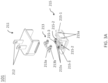
- FIG. 3A illustrates an explosion diagram of a plug unit 101, it includes plug top portion 211 having two plug pins 212, two metal contacts 213, which are made of metal reeds, and a plug base 215.
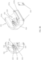
- FIG. 3B illustrates the bottom side of the plug top portion 211 with two metal contacts 213 being assembled onto.
- the plug top portion 211 has two pair of guiding bars (217a, 217b) disposed on outer edges of its side wall 216 to use for slidably engaging the power adapter unit 103 through corresponding guiding grooves 113b (see FIG. 2 ) located at the power adapter unit 103 and a recess 219 with an opening enclosed by the side wall 216.
- a plurality of guiding ribs 221 and protruding points 223 are used to position and fix the metal contacts 213, where the guiding ribs 221 serve as alignment guide to make each metal contact 213 engaging with corresponding electric contact pin 110 of the power adapter unit 103.
- each of the metal contacts 213 has a flat tail 213a and a clamp clip 213b, the flat tail 213a has a plurality of holes used to match the protruding points 223 for fixation the metal contact onto the plug top portion and also making electrical contact with the plug pins 212.
- the plug base 215 includes a front flange 215-1, rib-like support structure 215-2 with one end merged with the front flange 215-1 the other end with space enclosed by post structure 215-3, where the rib-like support structure 215-2 has two plug guiding slots 215a formed all the way from the front flange to the post structure for receiving the electric contact pins 110 of the power adapter unit 103 and interlock with the contact metals 213.
- the space 215s enclosed by post structure is used to embed and secure the clamp clip 213b of the contact metals 213.
- the guiding ribs 221 are respectively aligned with corresponding plug guiding slots 215a. Therefore, the assembled plug unit 101 has the metal contacts 213 embedded inside and located at the appropriate positions ready for engaging and making electrical contact with electric contact pins 110 of the power adapter unit 103.
- FIG. 4A illustrates locking mechanism of the assembled power supply 100
- the left of FIG. 4A shows a prospective view of the assembled power supply 100
- the right of FIG. 4A illustrates cross-sectional view along C-C section.
- the locking mechanism is established by the interlock between the tail hook of button 123 and baffle of front flange 215-1 of the plug unit 101.
- the button 123 is pressed down, locking between the tail hook of button 123 and the baffle of the front flange 215-1 of the plug unit 101 is released.
- the spring 121 is placed in the button recess 111 and the button 123 are disposed on top of the spring 121, where a portion of the button 123 including tail hook of the button 123 is disposed over the engaging base 107 through front gap 1131 of the side walls 113a to engage with the plug unit 101.
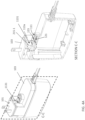
- FIG. 4B schematically illustrates the matching movement between the metal contacts 213 of the plug unit 101 and the electric contact pins 110 of the power adapter unit 103, which shows that each inner face of the clamp clip 213b near the tip has a small bump 213c used to interlock with through hole 110a of each electric contact pin 110 while the plug unit 101 is engaged with the power adapter unit 103.
- the interlock between the metal contacts and the electric pins is caused by the elastic force of the clamp clip 213b forcing the small bumps 213c near the tip of both arms of the clamp clip 213b to lock into through hole 110a of the electric contact pin 110.
- its main purpose is to demonstrate the engagement/matching between the metal contacts 213 of the plug unit 103 and the electric contact pins 110 of the power adapter unit 103, details of the plug unit 101 is skipped.
- FIG. 4C illustrates cross-sectional views of the assembled power supply 100 in various directions, to clearly demonstrate the interlock mechanism between the metal contacts 213 of the plug unit 101 and the electric contact pins 110 of the power adapter unit 103, details of the supporting structure inside the plug unit 101 is neglected, only the metal contacts 213 is depicted.
- the cross-sectional diagram shown in section A-A it clearly demonstrates how the clamp clip 213b of the metal contacts 213 interlock with the electric contact pins 110.
- the interlock between the metal contacts 213 and the electric contact pins 110 can further provide secured electric contacts while frequently plug and unplug during uses of the power supply 100, therefore prevent loose electric contact from happening.
- each of the electric contact pins 110 extends into the interior of the power adapter unit 103 for making electric connections with the power conversion module.
- a waterproof design can easily be achieved, since the electric contact pins 110 can be manufactured with top case 105a of the housing 105 by integrated molding to form an embedded structure where each pin of the electric contact pins 110 can extend toward both inside and outside the top case 105a of the housing 105 for making electric contacts, therefore after waterproof sealing between the top case 105a and the bottom case 105b and between the housing 105 and the DC cable 127 been completed, the power adapter unit 103 is waterproofed.
Landscapes
- Details Of Connecting Devices For Male And Female Coupling (AREA)
- Connector Housings Or Holding Contact Members (AREA)
Applications Claiming Priority (1)
| Application Number | Priority Date | Filing Date | Title |
|---|---|---|---|
| US18/360,569 US12609500B2 (en) | 2023-07-27 | 2023-07-27 | Power supply with interchangeable plugs |
Publications (1)
| Publication Number | Publication Date |
|---|---|
| EP4498535A1 true EP4498535A1 (fr) | 2025-01-29 |
Family
ID=88092981
Family Applications (1)
| Application Number | Title | Priority Date | Filing Date |
|---|---|---|---|
| EP23197599.6A Pending EP4498535A1 (fr) | 2023-07-27 | 2023-09-15 | Alimentation électrique à fiches interchangeables |
Country Status (5)
| Country | Link |
|---|---|
| US (1) | US12609500B2 (fr) |
| EP (1) | EP4498535A1 (fr) |
| CN (1) | CN119381813A (fr) |
| AU (1) | AU2023216747B1 (fr) |
| TW (1) | TWM665038U (fr) |
Families Citing this family (1)
| Publication number | Priority date | Publication date | Assignee | Title |
|---|---|---|---|---|
| US12609500B2 (en) * | 2023-07-27 | 2026-04-21 | Phihong Technology Co., Ltd. | Power supply with interchangeable plugs |
Citations (7)
| Publication number | Priority date | Publication date | Assignee | Title |
|---|---|---|---|---|
| DE3110609A1 (de) * | 1981-03-18 | 1982-10-07 | Siemens Ag | Mechanisch-elektrische steckverbindung |
| US20110223787A1 (en) * | 2010-03-12 | 2011-09-15 | Ampower Technology Co., Ltd. | Power device with a movable connector plug |
| CN202308685U (zh) * | 2011-09-30 | 2012-07-04 | 呈威电子(东莞)有限公司 | 可更换插头的电源转接器 |
| KR20170069118A (ko) * | 2015-12-10 | 2017-06-20 | 삼성전자주식회사 | 어댑터 어셈블리 |
| US9722377B1 (en) * | 2016-08-04 | 2017-08-01 | Edac Power Electronics Co., Ltd. | Pluggable power supply device |
| US20180241164A1 (en) * | 2014-08-25 | 2018-08-23 | Friwo Gerätebau Gmbh | Plug-in power supply with interchangeable mains plug units |
| US20200059052A1 (en) * | 2018-08-16 | 2020-02-20 | Samsung Electronics Co., Ltd. | Adapter |
Family Cites Families (16)
| Publication number | Priority date | Publication date | Assignee | Title |
|---|---|---|---|---|
| US1486790A (en) * | 1924-03-11 | Separable attachment plug | ||
| US2499296A (en) * | 1948-07-02 | 1950-02-28 | Buchanan Electrical Prod Corp | Electric connector |
| JP2769529B2 (ja) * | 1988-10-26 | 1998-06-25 | 朝日医理科株式会社 | コンタクトレンズ用消毒器 |
| US5634806A (en) * | 1994-02-24 | 1997-06-03 | Asian Micro Sources, Inc. | Interchangeable collapsible plug device for battery charger |
| US5613863A (en) * | 1995-05-18 | 1997-03-25 | Motorola, Inc. | Power transformer |
| US5684689A (en) * | 1996-06-19 | 1997-11-04 | Advanced Mobile Solutions, Inc. | Interchangeable plug power supply with automatically adjusting input voltage receiving mechanism |
| GB0308141D0 (en) * | 2003-03-24 | 2003-05-14 | Research In Motion Ltd | Battery charger adapter |
| CN2694564Y (zh) * | 2004-02-06 | 2005-04-20 | 诸葛瑞 | 可换插脚的电源插头 |
| TWI262634B (en) * | 2005-09-16 | 2006-09-21 | Hon Hai Prec Ind Co Ltd | Power supply devices and electronic products using the same |
| US7654838B1 (en) * | 2008-12-08 | 2010-02-02 | Rui Zhuge | Universal-conversion power cable |
| US8052441B2 (en) * | 2010-01-11 | 2011-11-08 | Hewlett-Packard Development Company, L.P. | Plug module |
| TWI415348B (zh) * | 2010-10-18 | 2013-11-11 | Leader Electronics Inc | Can replace the different plugs and can change the direction of the plug power conversion device |
| US10027078B2 (en) * | 2014-01-02 | 2018-07-17 | Sears Brands, L.L.C. | Slide battery and power tool for use with both slide and post batteries |
| US9166351B1 (en) * | 2014-05-30 | 2015-10-20 | Tongt-Huei Wang | Power adapting device |
| TW201628277A (zh) * | 2015-01-26 | 2016-08-01 | 台達電子工業股份有限公司 | 傳輸線的接頭結構及傳輸線 |
| US12609500B2 (en) * | 2023-07-27 | 2026-04-21 | Phihong Technology Co., Ltd. | Power supply with interchangeable plugs |
-
2023
- 2023-07-27 US US18/360,569 patent/US12609500B2/en active Active
- 2023-08-14 AU AU2023216747A patent/AU2023216747B1/en active Active
- 2023-08-23 TW TW113208161U patent/TWM665038U/zh unknown
- 2023-08-28 CN CN202311084959.3A patent/CN119381813A/zh active Pending
- 2023-09-15 EP EP23197599.6A patent/EP4498535A1/fr active Pending
Patent Citations (7)
| Publication number | Priority date | Publication date | Assignee | Title |
|---|---|---|---|---|
| DE3110609A1 (de) * | 1981-03-18 | 1982-10-07 | Siemens Ag | Mechanisch-elektrische steckverbindung |
| US20110223787A1 (en) * | 2010-03-12 | 2011-09-15 | Ampower Technology Co., Ltd. | Power device with a movable connector plug |
| CN202308685U (zh) * | 2011-09-30 | 2012-07-04 | 呈威电子(东莞)有限公司 | 可更换插头的电源转接器 |
| US20180241164A1 (en) * | 2014-08-25 | 2018-08-23 | Friwo Gerätebau Gmbh | Plug-in power supply with interchangeable mains plug units |
| KR20170069118A (ko) * | 2015-12-10 | 2017-06-20 | 삼성전자주식회사 | 어댑터 어셈블리 |
| US9722377B1 (en) * | 2016-08-04 | 2017-08-01 | Edac Power Electronics Co., Ltd. | Pluggable power supply device |
| US20200059052A1 (en) * | 2018-08-16 | 2020-02-20 | Samsung Electronics Co., Ltd. | Adapter |
Also Published As
| Publication number | Publication date |
|---|---|
| US12609500B2 (en) | 2026-04-21 |
| AU2023216747B1 (en) | 2025-01-02 |
| TWM665038U (zh) | 2025-01-01 |
| CN119381813A (zh) | 2025-01-28 |
| US20250038463A1 (en) | 2025-01-30 |
Similar Documents
| Publication | Publication Date | Title |
|---|---|---|
| US8382526B2 (en) | Power adapter with interchangeable connectors and power supply having the same | |
| US7179105B1 (en) | Power supply with a changeable plug element | |
| KR100975188B1 (ko) | 전기 잭 | |
| US20140273636A1 (en) | Active hdmi connector with integrated design | |
| EP4498535A1 (fr) | Alimentation électrique à fiches interchangeables | |
| TWM612275U (zh) | 電連接器 | |
| CN102299452B (zh) | 连接器装置 | |
| CN113823960A (zh) | 具有可移动式接地插脚的电源插头 | |
| JP7839897B2 (ja) | 給電装置、コンセント装置及びシステム | |
| CN215989457U (zh) | 母排结构及导电装置 | |
| CN211088587U (zh) | 一种自带电源的高速数据连接器 | |
| TWI686020B (zh) | 配線器具 | |
| CN204696402U (zh) | 一种电子设备 | |
| TWI672870B (zh) | 配線器具 | |
| JP6057372B2 (ja) | コネクタ | |
| CN110011086A (zh) | 导电端子及连接器 | |
| CN113555731A (zh) | 母排结构及导电装置 | |
| KR102503752B1 (ko) | 마이크로 유에스비 플러그 커넥터 | |
| CN110890661A (zh) | 一种自带电源的高速数据连接器 | |
| CN204695319U (zh) | 用于电子密钥设备的音频信号转接器及电子密钥设备 | |
| CN220544428U (zh) | 转换器 | |
| CN220984999U (zh) | 电连接结构、板端和线端连接器、转接线及连接组件 | |
| CN219477076U (zh) | 充电接口、数据线和电子设备 | |
| WO2013110333A1 (fr) | Coupleur c5/c6 mince | |
| KR200398887Y1 (ko) | 케이블 커넥터 |
Legal Events
| Date | Code | Title | Description |
|---|---|---|---|
| PUAI | Public reference made under article 153(3) epc to a published international application that has entered the european phase |
Free format text: ORIGINAL CODE: 0009012 |
|
| STAA | Information on the status of an ep patent application or granted ep patent |
Free format text: STATUS: REQUEST FOR EXAMINATION WAS MADE |
|
| 17P | Request for examination filed |
Effective date: 20231031 |
|
| AK | Designated contracting states |
Kind code of ref document: A1 Designated state(s): AL AT BE BG CH CY CZ DE DK EE ES FI FR GB GR HR HU IE IS IT LI LT LU LV MC ME MK MT NL NO PL PT RO RS SE SI SK SM TR |