EP4498622A2 - Procédé et appareil de communication - Google Patents
Procédé et appareil de communication Download PDFInfo
- Publication number
- EP4498622A2 EP4498622A2 EP24191937.2A EP24191937A EP4498622A2 EP 4498622 A2 EP4498622 A2 EP 4498622A2 EP 24191937 A EP24191937 A EP 24191937A EP 4498622 A2 EP4498622 A2 EP 4498622A2
- Authority
- EP
- European Patent Office
- Prior art keywords
- bwp
- terminal device
- indication information
- secondary cell
- dormant
- Prior art date
- Legal status (The legal status is an assumption and is not a legal conclusion. Google has not performed a legal analysis and makes no representation as to the accuracy of the status listed.)
- Pending
Links
Images



Classifications
-
- H—ELECTRICITY
- H04—ELECTRIC COMMUNICATION TECHNIQUE
- H04W—WIRELESS COMMUNICATION NETWORKS
- H04W72/00—Local resource management
- H04W72/04—Wireless resource allocation
- H04W72/044—Wireless resource allocation based on the type of the allocated resource
- H04W72/0453—Resources in frequency domain, e.g. a carrier in FDMA
-
- H—ELECTRICITY
- H04—ELECTRIC COMMUNICATION TECHNIQUE
- H04W—WIRELESS COMMUNICATION NETWORKS
- H04W52/00—Power management, e.g. Transmission Power Control [TPC] or power classes
- H04W52/02—Power saving arrangements
- H04W52/0209—Power saving arrangements in terminal devices
- H04W52/0212—Power saving arrangements in terminal devices managed by the network, e.g. network or access point is leader and terminal is follower
- H04W52/0216—Power saving arrangements in terminal devices managed by the network, e.g. network or access point is leader and terminal is follower using a pre-established activity schedule, e.g. traffic indication frame
-
- H—ELECTRICITY
- H04—ELECTRIC COMMUNICATION TECHNIQUE
- H04L—TRANSMISSION OF DIGITAL INFORMATION, e.g. TELEGRAPHIC COMMUNICATION
- H04L5/00—Arrangements affording multiple use of the transmission path
- H04L5/0001—Arrangements for dividing the transmission path
- H04L5/0003—Two-dimensional division
- H04L5/0005—Time-frequency
- H04L5/0007—Time-frequency the frequencies being orthogonal, e.g. OFDM(A) or DMT
- H04L5/001—Time-frequency the frequencies being orthogonal, e.g. OFDM(A) or DMT the frequencies being arranged in component carriers
-
- H—ELECTRICITY
- H04—ELECTRIC COMMUNICATION TECHNIQUE
- H04L—TRANSMISSION OF DIGITAL INFORMATION, e.g. TELEGRAPHIC COMMUNICATION
- H04L5/00—Arrangements affording multiple use of the transmission path
- H04L5/003—Arrangements for allocating sub-channels of the transmission path
- H04L5/0032—Distributed allocation, i.e. involving a plurality of allocating devices, each making partial allocation
-
- H—ELECTRICITY
- H04—ELECTRIC COMMUNICATION TECHNIQUE
- H04L—TRANSMISSION OF DIGITAL INFORMATION, e.g. TELEGRAPHIC COMMUNICATION
- H04L5/00—Arrangements affording multiple use of the transmission path
- H04L5/003—Arrangements for allocating sub-channels of the transmission path
- H04L5/0053—Allocation of signalling, i.e. of overhead other than pilot signals
-
- H—ELECTRICITY
- H04—ELECTRIC COMMUNICATION TECHNIQUE
- H04L—TRANSMISSION OF DIGITAL INFORMATION, e.g. TELEGRAPHIC COMMUNICATION
- H04L5/00—Arrangements affording multiple use of the transmission path
- H04L5/003—Arrangements for allocating sub-channels of the transmission path
- H04L5/0078—Timing of allocation
-
- H—ELECTRICITY
- H04—ELECTRIC COMMUNICATION TECHNIQUE
- H04L—TRANSMISSION OF DIGITAL INFORMATION, e.g. TELEGRAPHIC COMMUNICATION
- H04L5/00—Arrangements affording multiple use of the transmission path
- H04L5/0091—Signalling for the administration of the divided path, e.g. signalling of configuration information
- H04L5/0096—Indication of changes in allocation
-
- H—ELECTRICITY
- H04—ELECTRIC COMMUNICATION TECHNIQUE
- H04L—TRANSMISSION OF DIGITAL INFORMATION, e.g. TELEGRAPHIC COMMUNICATION
- H04L5/00—Arrangements affording multiple use of the transmission path
- H04L5/0091—Signalling for the administration of the divided path, e.g. signalling of configuration information
- H04L5/0096—Indication of changes in allocation
- H04L5/0098—Signalling of the activation or deactivation of component carriers, subcarriers or frequency bands
-
- H—ELECTRICITY
- H04—ELECTRIC COMMUNICATION TECHNIQUE
- H04W—WIRELESS COMMUNICATION NETWORKS
- H04W72/00—Local resource management
- H04W72/04—Wireless resource allocation
- H04W72/044—Wireless resource allocation based on the type of the allocated resource
- H04W72/0457—Variable allocation of band or rate
-
- H—ELECTRICITY
- H04—ELECTRIC COMMUNICATION TECHNIQUE
- H04W—WIRELESS COMMUNICATION NETWORKS
- H04W72/00—Local resource management
- H04W72/20—Control channels or signalling for resource management
- H04W72/23—Control channels or signalling for resource management in the downlink direction of a wireless link, i.e. towards a terminal
-
- H—ELECTRICITY
- H04—ELECTRIC COMMUNICATION TECHNIQUE
- H04W—WIRELESS COMMUNICATION NETWORKS
- H04W76/00—Connection management
- H04W76/20—Manipulation of established connections
- H04W76/28—Discontinuous transmission [DTX]; Discontinuous reception [DRX]
-
- H—ELECTRICITY
- H04—ELECTRIC COMMUNICATION TECHNIQUE
- H04L—TRANSMISSION OF DIGITAL INFORMATION, e.g. TELEGRAPHIC COMMUNICATION
- H04L5/00—Arrangements affording multiple use of the transmission path
- H04L5/003—Arrangements for allocating sub-channels of the transmission path
- H04L5/0058—Allocation criteria
- H04L5/0064—Rate requirement of the data, e.g. scalable bandwidth, data priority
-
- H—ELECTRICITY
- H04—ELECTRIC COMMUNICATION TECHNIQUE
- H04W—WIRELESS COMMUNICATION NETWORKS
- H04W76/00—Connection management
- H04W76/20—Manipulation of established connections
- H04W76/27—Transitions between radio resource control [RRC] states
-
- Y—GENERAL TAGGING OF NEW TECHNOLOGICAL DEVELOPMENTS; GENERAL TAGGING OF CROSS-SECTIONAL TECHNOLOGIES SPANNING OVER SEVERAL SECTIONS OF THE IPC; TECHNICAL SUBJECTS COVERED BY FORMER USPC CROSS-REFERENCE ART COLLECTIONS [XRACs] AND DIGESTS
- Y02—TECHNOLOGIES OR APPLICATIONS FOR MITIGATION OR ADAPTATION AGAINST CLIMATE CHANGE
- Y02D—CLIMATE CHANGE MITIGATION TECHNOLOGIES IN INFORMATION AND COMMUNICATION TECHNOLOGIES [ICT], I.E. INFORMATION AND COMMUNICATION TECHNOLOGIES AIMING AT THE REDUCTION OF THEIR OWN ENERGY USE
- Y02D30/00—Reducing energy consumption in communication networks
- Y02D30/70—Reducing energy consumption in communication networks in wireless communication networks
Definitions
- This application relates to the field of communications technologies, and in particular, to a communication method and an apparatus.
- carrier aggregation carrier aggregation
- CA carrier aggregation
- a plurality of component carriers may be configured for one terminal device.
- One of the CCs corresponds to a primary cell (primary cell, PCell), which is a cell in which the terminal device establishes an initial connection, a cell in which the terminal device reestablishes a radio resource control (radio resource control, RRC) connection, or a primary cell specified in a handover (handover) process.
- the PCell is responsible for RRC communication with the terminal device.
- Physical uplink control channel Physical up control channel (physical up control channel, PUCCH) information can be sent only in the PCell.
- the other CCs correspond to secondary cells (secondary cell, SCell).
- a network device may indicate, in the PCell, the terminal device whether to perform dormancy behavior in an SCell. If the network device indicates the terminal device to perform dormancy behavior, the terminal device does not monitor physical downlink control channel (physical downlink control channel, PDCCH) information in the corresponding SCell.
- PDCCH physical downlink control channel
- 5th generation (5 generation, 5G) new radio (new radio, NR) supports a bandwidth part (bandwidth part, BWP) technology, that is, supports transmission between a network device and a terminal device by occupying a part of bandwidth.
- BWP bandwidth part
- the network device may configure a plurality of BWPs for the terminal device, so that the terminal device can support a plurality of service types.
- a specific method in which the network device indicates the terminal device to perform dormancy behavior may be: configuring a dormant BWP (dormant BWP) in the SCell, and then indicating, in the PCell by using 1 bit (bit), the terminal device to switch between the dormant BWP and a non-dormant BWP (non-dormant BWP) in the SCell.
- a dormant BWP dormant BWP
- bit 1 bit
- '1' indicates switching from the dormant BWP to the non-dormant BWP
- '0' indicates switching from the non-dormant BWP to the dormant BWP.
- a current standard discusses only that the network device indicates the dormancy behavior of the terminal device by using indication information, but specific behavior performed by the terminal device after the terminal device receives the indication information is not clear.
- This application provides a communication method and an apparatus, so that when a terminal device receives indication information used by a network device to indicate the terminal device to work on a non-dormant BWP in a secondary cell, the terminal device can determine a specific BWP on which the terminal device is to work, and perform a corresponding operation.
- this application provides a communication method.
- the method includes: A terminal device receives indication information from a network device, where the indication information is used to indicate the terminal device to work on a non-dormant bandwidth part BWP in a first secondary cell; and the terminal device enables, according to the indication information, the terminal device to work on a first BWP, where the first BWP is the non-dormant BWP in the first secondary cell.
- the terminal device when receiving indication information used by the network device to indicate the terminal device to work on a non-dormant BWP in a secondary cell, the terminal device can determine a specific BWP on which the terminal device is to work, and work on the corresponding BWP.
- a specific method in which the terminal device enables the terminal device to work on the first BWP may be: The terminal device switches from a second BWP to the first BWP, where the second BWP is a dormant BWP or a non-dormant BWP currently used by the terminal device, and the first BWP is a first active BWP in the first secondary cell. In this way, the terminal device can work on the determined BWP.
- a specific method in which the terminal device enables the terminal device to work on the first BWP may be: The terminal device switches from a third BWP to the first BWP, where the third BWP is a dormant BWP or a non-dormant BWP currently used by the terminal device, and the first BWP is a BWP that is configured by the network device and to which the terminal device needs to switch. In this way, the terminal device can work on the determined BWP.
- a specific method in which the terminal device enables the terminal device to work on the first BWP may be: The terminal device switches from a fourth BWP to the first BWP, where the fourth BWP is a dormant BWP in the first secondary cell, and the terminal device works on the first BWP before switching to the fourth BWP. In this way, the terminal device can work on the determined BWP.
- a specific method in which the terminal device enables the terminal device to work on the first BWP may be: The terminal device switches from a fifth BWP to the first BWP, where the fifth BWP is a dormant BWP in the first secondary cell, and the first BWP is associated with the fifth BWP. In this way, the terminal device can work on the determined BWP.
- a specific method in which the terminal device enables the terminal device to work on the first BWP may be: When the terminal device currently uses the first BWP, the terminal device keeps the terminal device working on the first BWP. In this way, the terminal device can work on the determined BWP.
- this application provides a communication method.
- the method may include: A network device generates indication information, where the indication information is used to indicate a terminal device to work on a non-dormant bandwidth part BWP in a first secondary cell; and the network device sends the indication information to the terminal device, to enable the terminal device to work on a first BWP, where the first BWP is the non-dormant BWP in the first secondary cell.
- the terminal device when receiving indication information used by the network device to indicate the terminal device to work on a non-dormant BWP in a secondary cell, the terminal device can determine a specific BWP on which the terminal device is to work, and work on the corresponding BWP.
- this application provides a communication method.
- the method may include: A terminal device receives first configuration information from a network device, where the first configuration information is used to configure or indicate the terminal device to receive downlink control information, a category of indication information included in the downlink control information includes at least one of first indication information or second indication information or a category of indication information included in the downlink control information includes neither the first indication information nor the second indication information, the first indication information is used to indicate the terminal device whether to start an on duration timer in a first discontinuous reception DRX cycle, and the second indication information is used to indicate the terminal device whether to perform a dormancy operation in a secondary cell; and the terminal device monitors or does not monitor first downlink control information based on the first configuration information and the category of the indication information included in the downlink control information. In this way, specific behavior about whether the terminal device monitors the downlink control information is determined.
- the terminal device when the category of the indication information included in the downlink control information includes the first indication information, the terminal device receives second configuration information from the network device, and the second configuration information is used to configure that the category of the indication information included in the downlink control information includes the first indication information.
- the category of the indication information included in the downlink control information includes the first indication information by default.
- the terminal device monitors the first downlink control information; and when the first indication information is used to indicate the terminal device to start the on duration timer in the first DRX cycle, the terminal device starts the on duration timer in the first DRX cycle, and monitors a PDCCH in each cell within on duration in the first DRX cycle; or when the first indication information is used to indicate the terminal device not to start the on duration timer in the first DRX cycle, the terminal device does not start the on duration timer in the first DRX cycle, and does not monitor a PDCCH in each cell within on duration in the first DRX cycle. In this way, specific behavior about whether the terminal device monitors the downlink control information is determined.
- the terminal device monitors the first downlink control information; and when the first indication information is used to indicate the terminal device to start the on duration timer in the first DRX cycle, the terminal device starts the on duration timer in the first DRX cycle, monitors a physical downlink control channel PDCCH in a primary cell within on duration in the first DRX cycle, and determines, based on the second indication information, whether to monitor a PDCCH in the secondary cell within the on duration in the first DRX cycle; or when the first indication information is used to indicate the terminal device not to start the on duration timer in the first DRX cycle, the terminal device does not start the on duration timer in the first DRX cycle, and does not monitor a PDCCH in each cell within on duration in the first DRX cycle. In this way, specific behavior about whether the terminal device monitors the downlink control information when the category of the indication information included in the downlink control information
- the terminal device monitors the first downlink control information; the terminal device starts the on duration timer in the first DRX cycle, and monitors a PDCCH in a primary cell within on duration in the first DRX cycle; and the terminal device determines, based on the second indication information, whether to monitor a PDCCH in the secondary cell within the on duration in the first DRX cycle. In this way, specific behavior about whether the terminal device monitors the downlink control information when the category of the indication information included in the downlink control information includes the second indication information is determined.
- the terminal device when the category of the indication information included in the downlink control information includes neither the first indication information nor the second indication information, the terminal device does not monitor the first downlink control information. In this way, specific behavior about whether the terminal device monitors the downlink control information when the category of the indication information included in the downlink control information includes neither the first indication information nor the second indication information is determined.
- this application provides a communication method.
- the method may include: A network device sends first configuration information to the terminal device, where the first configuration information is used to configure or indicate the terminal device to receive downlink control information, a category of indication information included in the downlink control information includes at least one of first indication information or second indication information or a category of indication information included in the downlink control information includes neither the first indication information nor the second indication information, the first indication information is used to indicate the terminal device whether to start an on duration on duration timer in a first discontinuous reception DRX cycle, and the second indication information is used to indicate the terminal device whether to perform a dormancy operation in a secondary cell; and the network device sends or does not send first downlink control information based on the first configuration information and the category of the indication information included in the downlink control information. In this way, the terminal device can determine specific behavior about whether to monitor the downlink control information.
- this application further provides a terminal device.
- the terminal device has a function of implementing the terminal device in the method example in the first aspect or the third aspect.
- the function may be implemented by hardware, or may be implemented by hardware by executing corresponding software.
- the hardware or the software includes one or more modules corresponding to the function.
- a structure of the terminal device includes a processing unit and a transceiver unit. These units may perform corresponding functions in the method example in the first aspect or the third aspect. For details, refer to the detailed descriptions in the method example. Details are not described herein.
- a structure of the terminal device includes a transceiver and a processor, and optionally may further include a memory.
- the transceiver is configured to send and receive data, and communicate and interact with another device in a system.
- the processor is configured to support the terminal device in performing a corresponding function of the terminal device in the method in the first aspect or the third aspect.
- the memory is coupled to the processor, and the memory stores program instructions and data that are necessary for the terminal device.
- this application further provides a network device.
- the network device has a function of implementing the network device in the method example in the second aspect or the fourth aspect.
- the function may be implemented by hardware, or may be implemented by hardware by executing corresponding software.
- the hardware or the software includes one or more modules corresponding to the function.
- a structure of the network device includes a processing unit and a transceiver unit. These units may perform corresponding functions in the method example in the second aspect or the fourth aspect. For details, refer to the detailed descriptions in the method example. Details are not described herein.
- a structure of the network device includes a transceiver and a processor, and optionally may further include a memory.
- the transceiver is configured to send and receive data, and communicate and interact with another device in a system.
- the processor is configured to support the network device in performing a corresponding function of the network device in the method in the second aspect or the fourth aspect.
- the memory is coupled to the processor, and the memory stores program instructions and data that are necessary for the network device.
- this application further provides a communications system.
- the communications system includes the terminal device and the network device mentioned in at least one of the foregoing designs. Further, the network device in the communications system may perform any method performed by the network device in the foregoing methods, and the terminal device in the communications system may perform any method performed by the terminal device in the foregoing methods.
- this application provides a computer-readable storage medium.
- the computer-readable storage medium stores computer executable instructions, and when being invoked by a computer, the computer executable instructions are used to enable the computer to perform any one of the foregoing methods.
- this application provides a computer program product including instructions.
- the computer program product runs on a computer, the computer is enabled to perform any one of the foregoing methods.
- this application provides a chip.
- the chip is coupled to a memory, and is configured to read and execute program instructions stored in the memory, to implement any one of the foregoing methods.
- Embodiments of this application provide a communication method and an apparatus, so that when a terminal device receives indication information used by a network device to indicate the terminal device to work on a non-dormant BWP in a secondary cell, the terminal device can determine a specific BWP on which the terminal device is to work, and perform a corresponding operation.
- the method and the apparatus in this application are based on a same inventive concept.
- the method and the apparatus have similar problem resolving principles. Therefore, for implementation of the apparatus and the method, mutual reference may be made to each other. Details of repeated parts are not described.
- FIG. 1 shows an architecture of a possible communications system to which a communication method according to an embodiment of this application is applicable.
- the architecture of the communications system includes a network device and a terminal device.
- the network device is a device that has a wireless transceiver function or a chip that can be disposed in the network device.
- the network device includes but is not limited to: a gNB, a radio network controller (radio network controller, RNC), a NodeB (NodeB, NB), a base station controller (base station controller, BSC), a base transceiver station (base transceiver station, BTS), a home base station (for example, a home evolved NodeB, or a home NodeB, HNB), a baseband unit (baseband unit, BBU), an access point (access point, AP) in a wireless fidelity (wireless fidelity, WIFI) system, a wireless relay node, a wireless backhaul node, or a transmission and reception point (transmission and reception point, TRP, or transmission point, TP).
- the network device may alternatively be a network node, such as a baseband unit (BBU) or a distributed unit (distributed unit,
- the gNB may include a centralized unit (centralized unit, CU) and a DU.
- the gNB may further include a radio frequency unit (radio unit, RU).
- the CU implements some functions of the gNB
- the DU implements some functions of the gNB.
- the CU implements functions of a radio resource control (radio resource control, RRC) layer and a packet data convergence protocol (packet data convergence protocol, PDCP) layer
- the DU implements functions of a radio link control (radio link control, RLC) layer, a media access control (media access control, MAC) layer, and a physical (physical, PHY) layer.
- RRC radio resource control
- PDCP packet data convergence protocol
- the DU implements functions of a radio link control (radio link control, RLC) layer, a media access control (media access control, MAC) layer, and a physical (physical, PHY) layer.
- the network device may be a CU node, a DU node, or a device including a CU node and a DU node.
- the CU may be classified as a network device in an access network RAN, or the CU may be classified as a network device in a core network CN. This is not limited.
- the terminal device may also be referred to as user equipment (user equipment, UE), an access terminal, a subscriber unit, a subscriber station, a mobile station, a mobile console, a remote station, a remote terminal, a mobile device, a user terminal, a terminal, a wireless communications device, a user agent, or a user apparatus.
- user equipment user equipment
- UE user equipment
- an access terminal a subscriber unit, a subscriber station, a mobile station, a mobile console, a remote station, a remote terminal, a mobile device, a user terminal, a terminal, a wireless communications device, a user agent, or a user apparatus.
- the terminal device in the embodiments of this application may be a mobile phone (mobile phone), a tablet computer (Pad), a computer having a wireless transceiver function, a virtual reality (virtual reality, VR) terminal device, an augmented reality (augmented reality, AR) terminal device, a wireless terminal in industrial control (industrial control), a wireless terminal in self-driving (self-driving), a wireless terminal in telemedicine (remote medical), a wireless terminal in a smart grid (smart grid), a wireless terminal in transportation safety (transportation safety), a wireless terminal in a smart city (smart city), a wireless terminal in a smart home (smart home), or the like.
- An application scenario is not limited in the embodiments of this application.
- a terminal device having a wireless transceiver function and a chip that can be disposed in the terminal device are collectively referred to as terminal devices.
- the communications system shown in FIG. 1 may be but is not limited to a 5th generation (5th Generation, 5G) system, for example, a new radio access technology (new radio access technology, NR).
- 5G 5th Generation
- NR new radio access technology
- the method in the embodiments of this application is further applicable to various future communications systems, for example, a 6G system or another communications network.
- carrier aggregation carrier aggregation
- CA carrier aggregation
- a plurality of component carriers may be configured for one terminal device.
- One of the CCs corresponds to a primary cell (primary cell, PCell), which is a cell in which the terminal device establishes an initial connection, a cell in which the terminal device reestablishes a radio resource control (radio resource control, RRC) connection, or a primary cell specified in a handover (handover) process.
- the PCell is responsible for RRC communication with the terminal device.
- Physical uplink control channel Physical up control channel (physical up control channel, PUCCH) information can be sent in only the PCell.
- the other CCs correspond to secondary cells (secondary cell, SCell).
- a network device may indicate, in the PCell, the terminal device whether to perform dormancy behavior in an SCell. If the terminal device is indicated to perform dormancy behavior, the terminal device does not monitor a PDCCH in the corresponding SCell.
- a specific method is as follows: A dormant BWP (dormant BWP) is configured in the SCell. Then, in the PCell, the terminal device is indicated, by using 1-bit, to switch between the dormant BWP and a non-dormant BWP (non-dormant BWP) in the SCell.
- '1' indicates that the terminal device performs dormancy behavior (dormancy behavior) in the SCell, for example, switches from the dormant BWP to the non-dormant BWP
- '0' indicates that the terminal device performs non-dormancy behavior (non-dormancy behavior) in the SCell, for example, switches from the non-dormant BWP to the dormant BWP.
- the 1 -bit This is not limited in this application.
- the 1-bit indication in the PCell has the following two possibilities:
- a first possibility is as follows: When connected mode (CONNECTED mode, C)-discontinuous reception (discontinuous reception, DRX) is not configured for the terminal device, or C-DRX is configured for the terminal device and it is within a C-DRX active time (Active time), the indication may be carried in a downlink control information (downlink control information, DCI) format 0_1 or a DCI format 1_1.
- DCI downlink control information
- a second possibility is as follows: When C-DRX is configured for the terminal device and the indication is before on duration (OnDuration), the indication may be carried in a DCI format 3_0.
- the network device may send a PDCCH before DRX OnDuration.
- a DCI format corresponding to the PDCCH may be 3_0.
- the DCI format may also be referred to as another name (for example, a format 2_6). This is not limited in this application.
- the PDCCH may carry a wakeup indication to indicate whether a PDCCH needs to be monitored in a C-DRX cycle (cycle) after the PDCCH. If the terminal device is indicated not to wake up, regardless of a specific quantity of cells configured for the terminal device, the terminal device does not monitor a PDCCH in each cell.
- the DCI format 3_0 may further indicate dormancy behavior (dormancy behavior) in an SCell, and specifically indicate SCells on which the PDCCH needs to be monitored and SCells on which the PDCCH does not need to be monitored. The indication for the dormancy behavior does not affect the PCell.
- this application provides a communication method, to define specific behavior performed by the terminal device after the terminal device receives, from the network device, indication information indicating that the terminal device needs to work on a non-dormant BWP.
- a communication method provided in an embodiment of this application is applicable to the communications system shown in FIG. 1 .
- a specific procedure of the method may include the following steps.
- Step 201 A network device generates indication information, where the indication information is used to indicate a terminal device to work on a non-dormant BWP in a first secondary cell.
- Step 202 The network device sends the indication information to the terminal device.
- a specific method in which the network device sends the indication information to the terminal device may be: The network device sends the indication information to the terminal device in a primary cell.
- Step 203 The terminal device enables, according to the indication information, the terminal device to work on a first BWP, where the first BWP is the non-dormant BWP in the first secondary cell.
- the terminal device does not monitor a PDCCH signal on a dormant BWP, and monitors a PDCCH signal on a non-dormant BWP.
- the terminal device enables the terminal device to work on the first BWP may have the following five cases.
- Case a1 The terminal device switches from a second BWP to the first BWP, where the second BWP is a dormant BWP or a non-dormant BWP currently used by the terminal device, and the first BWP is a first active BWP (first active BWP) in the first secondary cell.
- the first active BWP is a specific BWP.
- a first active BWP in the secondary cell may be configured for the terminal device, to determine a specific BWP to be used when the terminal device works in the secondary cell for the first time.
- the network device configures the first active BWP in the first secondary cell, where the first active BWP is a BWP to which the terminal device needs to switch as long as the terminal device receives the indication information. Regardless of whether the terminal device currently works on the dormant BWP or the non-dormant BWP in the first secondary cell, as long as the terminal device does not work on the first active BWP, the terminal device switches to and works on the first active BWP in the first secondary cell.
- Case a2 The terminal device switches from a third BWP to the first BWP, where the third BWP is a dormant BWP or a non-dormant BWP currently used by the terminal device, and the first BWP is a BWP that is configured by the network device and to which the terminal device needs to switch.
- the third BWP is a dormant BWP or a non-dormant BWP currently used by the terminal device
- the first BWP is a BWP that is configured by the network device and to which the terminal device needs to switch.
- the network device configures a specific BWP (which is the first BWP herein) in the first secondary cell, where the specific BWP is a BWP to which the terminal device needs to switch as long as the terminal device receives the indication information.
- the terminal device switches to and works on the specific BWP in the first secondary cell.
- Case a3 The terminal device switches from a fourth BWP to the first BWP, where the fourth BWP is a dormant BWP in the first secondary cell, and the terminal device works on the first BWP before switching to the fourth BWP.
- Case a4 The terminal device switches from a fifth BWP to the first BWP, where the fifth BWP is a dormant BWP in the first secondary cell, and the first BWP is associated with the fifth BWP.
- each pair of BWPs are associated with each other.
- each pair of BWPs are one dormant BWP and one non-dormant BWP that are associated with each other.
- the terminal device switches between only two BWPs that are associated with each other.
- Case a5 When the terminal device currently uses the first BWP, the terminal device keeps the terminal device working on the first BWP.
- a possible scenario is that the first BWP is neither a first active BWP in the first secondary cell nor a BWP that is configured by the network device and to which the terminal device needs to switch.
- the method in the case 5a is used only in this scenario.
- Another possible scenario is that regardless of which BWP the first BWP is, as long as the first BWP is a non-dormant BWP, the method in the case a5 may be used.
- the network device separately performs the following operations.
- the network device determines that the terminal device switches from the second BWP to the first BWP, where the second BWP is the dormant BWP or the non-dormant BWP currently used by the terminal device, and the first BWP is the first active BWP in the first secondary cell.
- the network device determines that the terminal device switches from the third BWP to the first BWP, where the third BWP is the dormant BWP or the non-dormant BWP currently used by the terminal device, and the first BWP is the BWP that is configured by the network device and to which the terminal device needs to switch.
- the network device determines that the terminal device switches from the fourth BWP to the first BWP, where the fourth BWP is the dormant BWP in the first secondary cell, and the terminal device works on the first BWP before switching to the fourth BWP.
- the network device determines that the terminal device switches from the fifth BWP to the first BWP, where the fifth BWP is the dormant BWP in the first secondary cell, and the first BWP is associated with the fifth BWP.
- the network device determines that the terminal device keeps the terminal device working on the first BWP.
- the indication information is used to indicate the terminal device to work on the non-dormant bandwidth part BWP in the first secondary cell.
- the first secondary cell is an example used to describe the communication method provided in this application.
- the indication information is used to indicate the terminal device to work on a non-dormant BWP in one or more secondary cells, or to work on a dormant BWP in one or more secondary cells.
- the first secondary cell is any one of the one or more secondary cells.
- the terminal device when receiving indication information used by the network device to indicate the terminal device to work on a non-dormant BWP in a secondary cell, the terminal device can determine a specific BWP on which the terminal device is to work, and work on the corresponding BWP.
- the network device indicates that the terminal device needs to switch to a non-dormant BWP in a specific SCell. For example, if the terminal device works on a BWP 1 when receiving an indication, there are the following several cases.
- the terminal device switches to and works on a BWP 2 after receiving the indication, where the BWP 2 is a BWP used when the terminal device switches from the dormant BWP, for example, a first active BWP, a specific (default) non-dormant BWP configured by the network device, or an active BWP used by the terminal device before the terminal device switches to the dormant BWP.
- the BWP 2 is a BWP used when the terminal device switches from the dormant BWP, for example, a first active BWP, a specific (default) non-dormant BWP configured by the network device, or an active BWP used by the terminal device before the terminal device switches to the dormant BWP.
- the terminal device switches to and works on a BWP 2 after receiving the indication, where the BWP 2 is the BWP used when the terminal device switches from the dormant BWP, for example, a first active BWP, or a default non-dormant BWP configured by the network device; or the terminal device still works on the BWP 1.
- the BWP 1 is a non-dormant BWP and is a BWP used when the terminal device switches from a dormant BWP, the terminal device still works on the BWP 1.
- a plurality of BWPs may be configured for the UE in one cell. It is assumed that there are a plurality of non-dormant BWPs in one SCell.
- the following uses a specific example to describe which BWP the UE should switch to when the UE receives, in a PCell, an indication indicating that the UE needs to monitor a PDCCH in the SCell (that is, needs to work on a non-dormant BWP).
- a BWP 1, a BWP 2, and a BWP 3 are normal BWPs (that is, BWPs on which a PDCCH needs to be monitored, namely, non-dormant BWPs), and a BWP 4 is a dormant BWP (that is, a BWP on which a PDCCH does not need to be monitored).
- the UE initially works on the BWP 2, and at a first moment, the UE receives an indication in the PCell, and needs to switch to a dormant BWP (that is, the BWP 4).
- the UE receives an indication in the PCell, and needs to switch from the dormant BWP.
- the UE for determining of a specific BWP to which the UE switches from the BWP 4, there are the following three possible solutions:
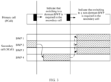
- the foregoing switching process may be shown in FIG. 3 .
- four normal BWPs are configured for the UE, and are a BWP 1, a BWP 2, a BWP 3, and a BWP 4.
- four dormant BWPs are further configured for the UE, and are a BWP 5, a BWP 6, a BWP 7, and a BWP 8, which respectively correspond to the BWP 1, the BWP 2, the BWP 3, and the BWP 4.
- an active BWP of the UE is the BWP 1
- the UE receives an indication from the network device, and needs to switch to a dormant BWP, the UE switches to the BWP 5.
- the UE When an active BWP of the UE is the BWP 5, if the UE receives an indication from the network device, and needs to switch to a non-dormant BWP, the UE switches to the BWP 1. In other words, the UE switches to a non-dormant BWP associated with a current dormant BWP.
- the UE works on a non-dormant BWP
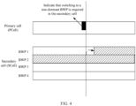
- the UE receives, in the PCell, an indication indicating that the UE needs to monitor a PDCCH in the SCell, whether the UE should switch between BWPs is specifically described below.
- a BWP 1, a BWP 2, and a BWP 3 are normal BWPs (that is, BWPs on which a PDCCH needs to be monitored, namely, non-dormant BWPs), and a BWP 4 is a dormant BWP (that is, a BWP on which a PDCCH does not need to be monitored).
- the BWP 1 is a BWP used when the UE switches from a dormant BWP in the SCell (or the first active BWP in the solution 1 in the foregoing example, or the BWP configured by a network side in the solution 3 in the foregoing example).
- a current active BWP of the UE is the BWP 2
- behavior of the UE may be implemented by using the following two solutions:
- the foregoing switching process may be shown in FIG. 4 .
- An embodiment of this application further provides another communication method, applicable to the communications system shown in FIG. 1 .
- a specific procedure of the method may include the following steps.
- Step 501 A terminal device receives first configuration information from a network device, where the first configuration information is used to configure or indicate the terminal device to receive downlink control information.
- a category of indication information included in the downlink control information includes at least one of first indication information or second indication information, or a category of indication information included in the downlink control information includes neither the first indication information nor the second indication information.
- the category of the indication information included in the downlink control information includes at least one of the first indication information or the second indication information.
- the category of the indication information included in the downlink control information includes at least the first indication information.
- the category of the indication information included in the downlink control information includes the second indication information.
- the category of the indication information included in the downlink control information includes the first indication information and the second indication information.
- the category of the indication information included in the downlink control information may be any case in the foregoing three scenarios, the three cases may randomly exist, and the category of the indication information included in the downlink control information is not limited.
- the first indication information is used to indicate the terminal device whether to start an on duration timer in a first DRX cycle
- the second indication information is used to indicate the terminal device whether to perform a dormancy operation in a secondary cell.
- Step 502 The terminal device monitors or does not monitor first downlink control information based on the first configuration information and the category of the indication information included in the downlink control information.
- Step 503 The network device sends or does not send the first downlink control information based on the first configuration information and the category of the indication information included in the downlink control information.
- step 502 and step 503 are merely an example, and the sequence of the two steps is not limited in this application.
- the terminal device when the category of the indication information included in the downlink control information includes the first indication information, the terminal device receives second configuration information from the network device, and the second configuration information is used to configure that the category of the indication information included in the downlink control information includes the first indication information.
- the category of the indication information included in the downlink control information includes the first indication information by default.
- the terminal device monitors the first downlink control information; and when the first indication information is used to indicate the terminal device to start the on duration timer in the first DRX cycle, the terminal device starts the on duration timer in the first DRX cycle, and monitors a PDCCH in each cell within on duration in the first DRX cycle; or when the first indication information is used to indicate the terminal device not to start the on duration timer in the first DRX cycle, the terminal device does not start the on duration timer in the first DRX cycle, and does not monitor a PDCCH in each cell within on duration in the first DRX cycle.
- the network device sends the first downlink control information to the terminal device; and when the first indication information is used to indicate the terminal device to start the on duration timer in the first DRX cycle, the network device sends a PDCCH to the terminal device in each cell within the on duration in the first DRX cycle; or when the first indication information is used to indicate the terminal device not to start the on duration timer in the first DRX cycle, the network device does not send a PDCCH to the terminal device in each cell within the on duration in the first DRX cycle.
- the terminal device monitors the first downlink control information; and when the first indication information is used to indicate the terminal device to start the on duration timer in the first DRX cycle, the terminal device starts the on duration timer in the first DRX cycle, monitors a physical downlink control channel PDCCH in a primary cell within on duration in the first DRX cycle, and determines, based on the second indication information, whether to monitor a PDCCH in the secondary cell within the on duration in the first DRX cycle; or when the first indication information is used to indicate the terminal device not to start the on duration timer in the first DRX cycle, the terminal device does not start the on duration timer in the first DRX cycle, and does not monitor a PDCCH in each cell within on duration in the first DRX cycle.
- the network device may send a PDCCH to the terminal device in the primary cell within the on duration in the first DRX cycle, and determine the second indication information based on whether the network device can send a PDCCH to the terminal device in the secondary cell within the on duration in the first DRX cycle; or when the first indication information is used to indicate the terminal device not to start the on duration timer in the first DRX cycle, the network device does not send a PDCCH in each cell within the on duration in the first DRX cycle; and the network device sends the first downlink control information to the terminal device.
- That the network device determines the second indication information based on whether the network device can send a PDCCH to the terminal device in the secondary cell within the on duration in the first DRX cycle may be specifically as follows: When the network device can send the PDCCH to the terminal device in the secondary cell within the on duration in the first DRX cycle, the network device determines that the second indication information is used to indicate that the network can send the PDCCH to the terminal device in the secondary cell within the on duration in the first DRX cycle. For example, the network device may determine that the second indication information is " 1".
- the second indication information is used to indicate that the network device cannot send the PDCCH to the terminal device in the secondary cell within the on duration in the first DRX cycle. For example, the network device may determine that the second indication information is "0".
- the terminal device monitors the first downlink control information; the terminal device starts the on duration timer in the first DRX cycle, and monitors a PDCCH in a primary cell within on duration in the first DRX cycle; and the terminal device determines, based on the second indication information, whether to monitor a PDCCH in the secondary cell within the on duration in the first DRX cycle.
- the network device sends a PDCCH to the terminal device in the primary cell within the on duration in the first DRX cycle; the network device determines the second indication information based on whether the network device can send a PDCCH to the terminal device in the secondary cell within the on duration in the first DRX cycle; and the network device sends the first downlink control information to the terminal device.
- the network device determines the second indication information based on whether the network device can send a PDCCH to the terminal device in the secondary cell within the on duration in the first DRX cycle is similar to the case in the previous example (namely, the foregoing another example). Mutual reference may be made, and details are not described herein again.
- the terminal device when the category of the indication information included in the downlink control information includes neither the first indication information nor the second indication information, the terminal device does not monitor the first downlink control information.
- the network device does not send the first downlink control information to the terminal device.
- the first downlink control information is before a start moment of the on duration in the first DRX cycle, for example, as shown in FIG. 6 .
- the DCI format 3_0 indicates wakeup (wakeup) and dormancy (dormancy) behavior (that is, when a category of indication information included in the DCI format 3_0 may be the first indication information and the second indication information), there may be the following four indication function combinations:
- UE has two types of possible behavior.
- the UE When the combination is an invalid combination, that is, when the UE is configured to monitor DCI, the UE needs to receive at least a wakeup indication in the DCI.
- UE behavior should be that monitoring always needs to be performed in a PCell of the UE within OnDuration, and whether monitoring is performed in an SCell is determined based on a specific indication.
- UE also has two types of possible behavior.
- the combination is an invalid combination, that is, when the UE is configured to monitor DCI, at least one indication function needs to be configured for the UE.
- the UE may not monitor the DCI.
- an embodiment of this application further provides a terminal device.
- the terminal device is used in the communications system shown in FIG. 1 .
- the terminal device may be configured to implement a function of the terminal device in the communication method shown in FIG. 2 or FIG. 5 .
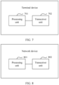
- the terminal device may include a processing unit 701 and a transceiver unit 702.
- the terminal device when the terminal device implements a function of the terminal device in the communication method shown in FIG. 2 , details may be as follows.
- the transceiver unit 702 is configured to receive indication information from a network device, where the indication information is used to indicate the terminal device to work on a non-dormant bandwidth part BWP in a first secondary cell.
- the processing unit 701 is configured to enable, according to the indication information, the terminal device to work on a first BWP, where the first BWP is the non-dormant BWP in the first secondary cell.
- the processing unit 701 when enabling the terminal device to work on the first BWP, is specifically configured to switch from a second BWP to the first BWP, where the second BWP is a dormant BWP or a non-dormant BWP currently used by the terminal device, and the first BWP is a first active BWP in the first secondary cell.
- the processing unit 701 when enabling the terminal device to work on the first BWP, is specifically configured to switch from a third BWP to the first BWP, where the third BWP is a dormant BWP or a non-dormant BWP currently used by the terminal device, and the first BWP is a BWP that is configured by the network device and to which the terminal device needs to switch.
- the processing unit 701 when enabling the terminal device to work on the first BWP, is specifically configured to switch from a fourth BWP to the first BWP, where the fourth BWP is a dormant BWP in the first secondary cell, and the terminal device works on the first BWP before switching to the fourth BWP.
- the processing unit 701 when enabling the terminal device to work on the first BWP, is specifically configured to switch from a fifth BWP to the first BWP, where the fifth BWP is a dormant BWP in the first secondary cell, and the first BWP is associated with the fifth BWP.
- the processing unit 701 when enabling the terminal device to work on the first BWP, is specifically configured to: when the terminal device currently uses the first BWP, keep the terminal device working on the first BWP.
- the first BWP is neither a first active BWP in the first secondary cell nor a BWP that is configured by the network device and to which the terminal device needs to switch.
- the transceiver unit 702 when receiving the indication information from the network device, is specifically configured to receive the indication information from the network device in a primary cell.
- the terminal device when the terminal device implements a function of the terminal device in the communication method shown in FIG. 5 , details may be as follows.
- the transceiver unit 702 is configured to receive first configuration information from a network device, where the first configuration information is used to configure or indicate the terminal device to receive downlink control information.
- a category of indication information included in the downlink control information includes at least one of first indication information or second indication information, or a category of indication information included in the downlink control information includes neither the first indication information nor the second indication information.
- the first indication information is used to indicate the terminal device whether to start an on duration on duration timer in a first discontinuous reception DRX cycle
- the second indication information is used to indicate the terminal device whether to perform a dormancy operation in a secondary cell.
- the processing unit 701 is configured to monitor or not monitor first downlink control information based on the first configuration information and the category of the indication information included in the downlink control information.
- the transceiver unit 702 is further configured to receive second configuration information from the network device, where the second configuration information is used to configure that the category of the indication information included in the downlink control information includes the first indication information; or the category of the indication information included in the downlink control information includes the first indication information by default.
- the processing unit 701 is further configured to: monitor the first downlink control information; and when the first indication information is used to indicate the terminal device to start the on duration timer in the first DRX cycle, start the on duration timer in the first DRX cycle, and monitor a PDCCH in each cell within on duration in the first DRX cycle; or when the first indication information is used to indicate the terminal device not to start the on duration timer in the first DRX cycle, not start the on duration timer in the first DRX cycle, and not monitor a PDCCH in each cell within on duration in the first DRX cycle.
- the processing unit 701 is further configured to: monitor the first downlink control information; and when the first indication information is used to indicate the terminal device to start the on duration timer in the first DRX cycle, start the on duration timer in the first DRX cycle, monitor a physical downlink control channel PDCCH in a primary cell within on duration in the first DRX cycle, and determine, based on the second indication information, whether to monitor a PDCCH in the secondary cell within the on duration in the first DRX cycle; or when the first indication information is used to indicate the terminal device not to start the on duration timer in the first DRX cycle, not start the on duration timer in the first DRX cycle, and not monitor a PDCCH in each cell within on duration in the first DRX cycle.
- the processing unit 701 is further configured to: monitor the first downlink control information; start the on duration timer in the first DRX cycle, and monitor a PDCCH in a primary cell within on duration in the first DRX cycle; and determine, based on the second indication information, whether to monitor a PDCCH in the secondary cell within the on duration in the first DRX cycle.
- the processing unit 701 is further configured to not monitor the first downlink control information.
- the first downlink control information is before a start moment of the on duration on duration in the first DRX cycle.
- an embodiment of this application further provides a network device.
- the network device is used in the communications system shown in FIG. 1 .
- the network device may be configured to implement the communication method shown in FIG. 2 or FIG. 5 .
- the network device may include a processing unit 801 and a transceiver unit 802.
- the network device when the network device implements a function of the network device in the communication method shown in FIG. 2 , details may be as follows.
- the processing unit 801 is configured to generate indication information, where the indication information is used to indicate a terminal device to work on a non-dormant bandwidth part BWP in a first secondary cell.
- the transceiver unit 802 is configured to send the indication information to the terminal device, to enable the terminal device to work on a first BWP, where the first BWP is the non-dormant BWP in the first secondary cell.
- the processing unit 801 is further configured to determine that the terminal device switches from a second BWP to the first BWP, where the second BWP is a dormant BWP or a non-dormant BWP currently used by the terminal device, and the first BWP is a first active BWP in the first secondary cell.
- the processing unit 801 is further configured to determine that the terminal device switches from a third BWP to the first BWP, where the third BWP is a dormant BWP or a non-dormant BWP currently used by the terminal device, and the first BWP is a BWP that is configured by the network device and to which the terminal device needs to switch.
- the processing unit 801 is further configured to determine that the terminal device switches from a fourth BWP to the first BWP, where the fourth BWP is a dormant BWP in the first secondary cell, and the terminal device works on the first BWP before switching to the fourth BWP.
- the processing unit 801 is further configured to determine that the terminal device switches from a fifth BWP to the first BWP, where the fifth BWP is a dormant BWP in the first secondary cell, and the first BWP is associated with the fifth BWP.
- the processing unit 801 is further configured to: when the terminal device currently uses the first BWP, determine that the terminal device keeps the terminal device working on the first BWP.
- the first BWP is neither a first active BWP in the first secondary cell nor a BWP that is configured by the network device and to which the terminal device needs to switch.
- the transceiver unit 802 when sending the indication information to the terminal device, is specifically configured to send the indication information to the terminal device in a primary cell.
- the transceiver unit 802 is configured to send first configuration information to a terminal device, where the first configuration information is used to configure or indicate the terminal device to receive downlink control information.
- a category of indication information included in the downlink control information includes at least one of first indication information or second indication information, or a category of indication information included in the downlink control information includes neither the first indication information nor the second indication information.
- the first indication information is used to indicate the terminal device whether to start an on duration on duration timer in a first discontinuous reception DRX cycle
- the second indication information is used to indicate the terminal device whether to perform a dormancy operation in a secondary cell.
- the processing unit 801 is configured to send or not send first downlink control information based on the first configuration information and the category of the indication information included in the downlink control information.
- the transceiver unit 802 is further configured to send second configuration information to the terminal device, where the second configuration information is used to configure that the category of the indication information included in the downlink control information includes the first indication information; or the category of the indication information included in the downlink control information includes the first indication information by default.
- the transceiver unit 802 is further configured to: send the first downlink control information to the terminal device; and when the first indication information is used to indicate the terminal device to start the on duration timer in the first DRX cycle, send a PDCCH to the terminal device in each cell within on duration in the first DRX cycle; or when the first indication information is used to indicate the terminal device not to start the on duration timer in the first DRX cycle, not send a PDCCH to the terminal device in each cell within on duration in the first DRX cycle.
- the transceiver unit 802 when the category of the indication information included in the downlink control information includes the first indication information and the second indication information, if the first indication information is used to indicate the terminal device to start the on duration timer in the first DRX cycle, the transceiver unit 802 is further configured to send a PDCCH to the terminal device in a primary cell within on duration in the first DRX cycle, and the processing unit 801 is further configured to determine the second indication information based on whether the network device sends a PDCCH to the terminal device in the secondary cell within the on duration in the first DRX cycle; or if the first indication information is used to indicate the terminal device not to start the on duration timer in the first DRX cycle, the transceiver unit 802 is further configured to not send a PDCCH in each cell within on duration in the first DRX cycle; and the transceiver unit 802 is further configured to send the first downlink control information to the terminal device.
- the transceiver unit 802 is further configured to send a PDCCH to the terminal device in a primary cell within on duration in the first DRX cycle; the processing unit 801 is further configured to determine the second indication information based on whether the network device sends a PDCCH to the terminal device in the secondary cell within the on duration in the first DRX cycle; and the transceiver unit 802 is further configured to send the first downlink control information to the terminal device.
- the transceiver unit 802 is further configured to not send the first downlink control information to the terminal device.
- the first downlink control information is before a start moment of the on duration on duration in the first DRX cycle.
- division into units is an example, and is merely logical function division. During actual implementation, there may be another division manner.
- Function units in the embodiments of this application may be integrated into one processing unit, or each of the units may exist alone physically, or two or more units may be integrated into one unit.
- the integrated unit may be implemented in a form of hardware, or may be implemented in a form of a software function unit.
- the integrated unit When the integrated unit is implemented in a form of a software function unit and sold or used as an independent product, the integrated unit may be stored in a computer-readable storage medium. Based on such an understanding, the technical solutions of this application essentially, or the part contributing to the conventional technology, or all or some of the technical solutions may be implemented in a form of a software product.
- the computer software product is stored in a storage medium and includes several instructions for instructing a computer device (which may be a personal computer, a server, or a network device) or a processor (processor) to perform all or some of the steps of the methods described in the embodiments of this application.
- the foregoing storage medium includes any medium that can store program code, such as a USB flash drive, a removable hard disk, a read-only memory (read-only memory, ROM), a random access memory (random access memory, RAM), a magnetic disk, or a compact disc.
- program code such as a USB flash drive, a removable hard disk, a read-only memory (read-only memory, ROM), a random access memory (random access memory, RAM), a magnetic disk, or a compact disc.
- an embodiment of this application further provides a terminal device.
- the terminal device is configured to implement a function of the terminal device in the communication method shown in FIG. 2 or FIG. 5 .
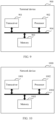
- the terminal device 900 includes a transceiver 901 and a processor 902.
- the processor 902 may be a central processing unit (central processing unit, CPU), a network processor (network processor, NP), or a combination of a CPU and an NP.
- the processor 902 may further include a hardware chip.
- the hardware chip may be an application-specific integrated circuit (application-specific integrated circuit, ASIC), a programmable logic device (programmable logic device, PLD), or a combination thereof.
- the PLD may be a complex programmable logic device (complex programmable logic device, CPLD), a field-programmable gate array (field-programmable gate array, FPGA), generic array logic (generic array logic, GAL), or any combination thereof.
- the processor 902 may implement the foregoing function by hardware or by hardware executing corresponding software.
- the transceiver 901 and the processor 902 are connected to each other.
- the transceiver 901 and the processor 902 are connected to each other by using a bus 904.
- the bus 904 may be a peripheral component interconnect (Peripheral Component Interconnect, PCI) bus, an extended industry standard architecture (Extended Industry Standard Architecture, EISA) bus, or the like.
- PCI peripheral component interconnect
- EISA Extended Industry Standard Architecture
- the bus may be classified into an address bus, a data bus, a control bus, and the like. For ease of representation, only one thick line is used to represent the bus in FIG. 9 , but this does not mean that there is only one bus or only one type of bus.
- the terminal device may further include a memory 903, and the memory 903 is configured to store a program and the like.
- the program may include program code, and the program code includes computer operation instructions.
- the memory 903 may include a RAM, and may further include a non-volatile memory (non-volatile memory), for example, at least one magnetic disk memory.
- the processor 902 performs the application program stored in the memory 903 to implement the foregoing function, so as to implement the communication method shown in FIG 2 or FIG. 5 .
- the transceiver 901 may implement sending and receiving operations performed by the terminal device in the embodiment shown in FIG. 2
- the processor 902 may implement an operation other than the sending and receiving operations performed by the terminal device in the embodiment shown in FIG. 2 .
- the transceiver 901 may implement sending and receiving operations performed by the terminal device in the embodiment shown in FIG. 5
- the processor 902 may implement an operation other than the sending and receiving operations performed by the terminal device in the embodiment shown in FIG. 5 .
- an embodiment of this application further provides a network device.
- the network device is configured to implement a function of the network device in the communication method shown in FIG. 2 or FIG. 5 .
- the network device 1000 includes a transceiver 1001 and a processor 1002.
- the processor 1002 may be a central processing unit (central processing unit, CPU), a network processor (network processor, NP), or a combination of a CPU and an NP.
- the processor 1002 may further include a hardware chip.
- the hardware chip may be an application-specific integrated circuit (application-specific integrated circuit, ASIC), a programmable logic device (programmable logic device, PLD), or a combination thereof.
- the PLD may be a complex programmable logic device (complex programmable logic device, CPLD), a field-programmable gate array (field-programmable gate array, FPGA), generic array logic (generic array logic, GAL), or any combination thereof.
- the processor 1002 may implement the foregoing function by hardware or by hardware executing corresponding software.
- the transceiver 1001 and the processor 1002 are connected to each other.
- the transceiver 1001 and the processor 1002 are connected to each other by using a bus 1004.
- the bus 1004 may be a peripheral component interconnect (Peripheral Component Interconnect, PCI) bus, an extended industry standard architecture (Etended Industry Standard Architecture, EISA) bus, or the like.
- PCI peripheral component interconnect
- EISA Extended Industry Standard Architecture
- the bus may be classified into an address bus, a data bus, a control bus, and the like. For ease of representation, only one thick line is used to represent the bus in FIG. 10 , but this does not mean that there is only one bus or only one type of bus.
- the network device may further include a memory 1003, and the memory 1003 is configured to store a program and the like.
- the program may include program code, and the program code includes computer operation instructions.
- the memory 1003 may include a RAM, and may further include a non-volatile memory (non-volatile memory), for example, at least one magnetic disk memory.
- the processor 1002 performs the application program stored in the memory 1003 to implement the foregoing function, so as to implement the communication method shown in FIG 2 or FIG. 5 .
- the transceiver 1001 may implement sending and receiving operations performed by the network device in the embodiment shown in FIG. 2
- the processor 1002 may implement an operation other than the sending and receiving operations performed by the network device in the embodiment shown in FIG. 2 .
- the transceiver 1001 may implement sending and receiving operations performed by the network device in the embodiment shown in FIG. 5
- the processor 1002 may implement an operation other than the sending and receiving operations performed by the network device in the embodiment shown in FIG. 5 .
- a communication method includes:
- Embodiment 2 In the method according to Embodiment 1, the enabling, by the terminal device, the terminal device to work on a first BWP includes: switching, by the terminal device, from a second BWP to the first BWP, where the second BWP is a dormant BWP or a non-dormant BWP currently used by the terminal device, and the first BWP is a first active BWP in the first secondary cell.
- Embodiment 3 In the method according to Embodiment 1, the enabling, by the terminal device, the terminal device to work on a first BWP includes: switching, by the terminal device, from a third BWP to the first BWP, where the third BWP is a dormant BWP or a non-dormant BWP currently used by the terminal device, and the first BWP is a BWP that is configured by the network device and to which the terminal device needs to switch.
- Embodiment 4 In the method according to Embodiment 1, the enabling, by the terminal device, the terminal device to work on a first BWP includes: switching, by the terminal device, from a fourth BWP to the first BWP, where the fourth BWP is a dormant BWP in the first secondary cell, and the terminal device works on the first BWP before switching to the fourth BWP.
- Embodiment 5 In the method according to Embodiment 1, the enabling, by the terminal device, the terminal device to work on a first BWP includes: switching, by the terminal device, from a fifth BWP to the first BWP, where the fifth BWP is a dormant BWP in the first secondary cell, and the first BWP is associated with the fifth BWP.
- Embodiment 6 In the method according to Embodiment 1, the enabling, by the terminal device, the terminal device to work on a first BWP includes: when the terminal device currently uses the first BWP, keeping, by the terminal device, the terminal device working on the first BWP.
- Embodiment 7 In the method according to Embodiment 6, the first BWP is neither a first active BWP in the first secondary cell nor a BWP that is configured by the network device and to which the terminal device needs to switch.
- Embodiment 8 In the method according to any one of Embodiment 1 to Embodiment 7, the receiving, by a terminal device, indication information from a network device includes: receiving, by the terminal device, the indication information from the network device in a primary cell.
- a communication method includes:
- Embodiment 10 In the method according to Embodiment 9, the method further includes: determining, by the network device, that the terminal device switches from a second BWP to the first BWP, where the second BWP is a dormant BWP or a non-dormant BWP currently used by the terminal device, and the first BWP is a first active BWP in the first secondary cell.
- Embodiment 11 In the method according to Embodiment 9, the method further includes: determining, by the network device, that the terminal device switches from a third BWP to the first BWP, where the third BWP is a dormant BWP or a non-dormant BWP currently used by the terminal device, and the first BWP is a BWP that is configured by the network device and to which the terminal device needs to switch.
- Embodiment 12 In the method according to Embodiment 9, the method further includes: determining, by the network device, that the terminal device switches from a fourth BWP to the first BWP, where the fourth BWP is a dormant BWP in the first secondary cell, and the terminal device works on the first BWP before switching to the fourth BWP.
- Embodiment 13 In the method according to Embodiment 9, the method further includes: determining, by the network device, that the terminal device switches from a fifth BWP to the first BWP, where the fifth BWP is a dormant BWP in the first secondary cell, and the first BWP is associated with the fifth BWP.
- Embodiment 14 In the method according to Embodiment 9, the method further includes: when the terminal device currently uses the first BWP, determining, by the network device, that the terminal device keeps the terminal device working on the first BWP.
- Embodiment 15 In the method according to Embodiment 14, the first BWP is neither a first active BWP in the first secondary cell nor a BWP that is configured by the network device and to which the terminal device needs to switch.
- Embodiment 16 In the method according to any one of Embodiment 9 to Embodiment 15, the sending, by the network device, the indication information to the terminal device includes: sending by the network device, the indication information to the terminal device in a primary cell.
- a terminal device includes:
- Embodiment 18 In the terminal device according to Embodiment 17, when enabling the terminal device to work on the first BWP, the processing unit is specifically configured to: switch from a second BWP to the first BWP, where the second BWP is a dormant BWP or a non-dormant BWP currently used by the terminal device, and the first BWP is a first active BWP in the first secondary cell.
- Embodiment 19 In the terminal device according to Embodiment 17, when enabling the terminal device to work on the first BWP, the processing unit is specifically configured to: switch from a third BWP to the first BWP, where the third BWP is a dormant BWP or a non-dormant BWP currently used by the terminal device, and the first BWP is a BWP that is configured by the network device and to which the terminal device needs to switch.
- the processing unit when enabling the terminal device to work on the first BWP, the processing unit is specifically configured to: switch from a third BWP to the first BWP, where the third BWP is a dormant BWP or a non-dormant BWP currently used by the terminal device, and the first BWP is a BWP that is configured by the network device and to which the terminal device needs to switch.
- Embodiment 20 In the terminal device according to Embodiment 17, when enabling the terminal device to work on the first BWP, the processing unit is specifically configured to: switch from a fourth BWP to the first BWP, where the fourth BWP is a dormant BWP in the first secondary cell, and the terminal device works on the first BWP before switching to the fourth BWP.
- Embodiment 21 In the terminal device according to Embodiment 17, when enabling the terminal device to work on the first BWP, the processing unit is specifically configured to: switch from a fifth BWP to the first BWP, where the fifth BWP is a dormant BWP in the first secondary cell, and the first BWP is associated with the fifth BWP.
- Embodiment 22 In the terminal device according to Embodiment 17, when enabling the terminal device to work on the first BWP, the processing unit is specifically configured to: when the terminal device currently uses the first BWP, keep the terminal device working on the first BWP.
- Embodiment 23 In the terminal device according to Embodiment 22, the first BWP is neither a first active BWP in the first secondary cell nor a BWP that is configured by the network device and to which the terminal device needs to switch.
- Embodiment 24 In the terminal device according to any one of Embodiment 17 to Embodiment 23, when receiving the indication information from the network device, the transceiver unit is specifically configured to: receive the indication information from the network device in a primary cell.
- a network device includes:
- Embodiment 26 In the network device according to Embodiment 25, the processing unit is further configured to: determine that the terminal device switches from a second BWP to the first BWP, where the second BWP is a dormant BWP or a non-dormant BWP currently used by the terminal device, and the first BWP is a first active BWP in the first secondary cell.
- the processing unit is further configured to: determine that the terminal device switches from a second BWP to the first BWP, where the second BWP is a dormant BWP or a non-dormant BWP currently used by the terminal device, and the first BWP is a first active BWP in the first secondary cell.
- Embodiment 27 In the network device according to Embodiment 25, the processing unit is further configured to: determine that the terminal device switches from a third BWP to the first BWP, where the third BWP is a dormant BWP or a non-dormant BWP currently used by the terminal device, and the first BWP is a BWP that is configured by the network device and to which the terminal device needs to switch.
- the third BWP is a dormant BWP or a non-dormant BWP currently used by the terminal device
- the first BWP is a BWP that is configured by the network device and to which the terminal device needs to switch.
- Embodiment 28 In the network device according to Embodiment 25, the processing unit is further configured to: determine that the terminal device switches from a fourth BWP to the first BWP, where the fourth BWP is a dormant BWP in the first secondary cell, and the terminal device works on the first BWP before switching to the fourth BWP.
- Embodiment 29 In the network device according to Embodiment 25, the processing unit is further configured to: determine that the terminal device switches from a fifth BWP to the first BWP, where the fifth BWP is a dormant BWP in the first secondary cell, and the first BWP is associated with the fifth BWP.
- Embodiment 30 In the network device according to Embodiment 25, the processing unit is further configured to: when the terminal device currently uses the first BWP, determine that the terminal device keeps the terminal device working on the first BWP.
- Embodiment 31 In the network device according to Embodiment 30, the first BWP is neither a first active BWP in the first secondary cell nor a BWP that is configured by the network device and to which the terminal device needs to switch.
- Embodiment 32 In the network device according to any one of Embodiment 25 to Embodiment 31, when sending the indication information to the terminal device, the transceiver unit is specifically configured to: send the indication information to the terminal device in a primary cell.
- a terminal device includes:
- a network device includes:
- Embodiment 35 A communications system includes a network device and a terminal device.
- the network device is configured to: generate indication information, and send the indication information to the terminal device, where the indication information is used to indicate the terminal device to work on a non-dormant bandwidth part BWP in a first secondary cell.
- the terminal device is configured to enable, according to the indication information, the terminal device to work on a first BWP, where the first BWP is the non-dormant BWP in the first secondary cell.
- Embodiment 36 In the communications system according to Embodiment 35, when enabling the terminal device to work on the first BWP, the terminal device is specifically configured to: switch from a second BWP to the first BWP, where the second BWP is a dormant BWP or a non-dormant BWP currently used by the terminal device, and the first BWP is a first active BWP in the first secondary cell.
- the terminal device when enabling the terminal device to work on the first BWP, the terminal device is specifically configured to: switch from a second BWP to the first BWP, where the second BWP is a dormant BWP or a non-dormant BWP currently used by the terminal device, and the first BWP is a first active BWP in the first secondary cell.
- Embodiment 37 In the communications system according to Embodiment 35 or Embodiment 36, the network device is further configured to: determine that the terminal device switches from the second BWP to the first BWP, where the second BWP is the dormant BWP or the non-dormant BWP currently used by the terminal device, and the first BWP is the first active BWP in the first secondary cell.
- Embodiment 38 In the communications system according to Embodiment 35, when enabling the terminal device to work on the first BWP, the terminal device is specifically configured to: switch from a third BWP to the first BWP, where the third BWP is a dormant BWP or a non-dormant BWP currently used by the terminal device, and the first BWP is a BWP that is configured by the network device and to which the terminal device needs to switch.
- the terminal device when enabling the terminal device to work on the first BWP, the terminal device is specifically configured to: switch from a third BWP to the first BWP, where the third BWP is a dormant BWP or a non-dormant BWP currently used by the terminal device, and the first BWP is a BWP that is configured by the network device and to which the terminal device needs to switch.
- Embodiment 39 In the communications system according to Embodiment 35 or Embodiment 38, the network device is further configured to: determine that the terminal device switches from the third BWP to the first BWP, where the third BWP is the dormant BWP or the non-dormant BWP currently used by the terminal device, and the first BWP is the BWP that is configured by the network device and to which the terminal device needs to switch.
- Embodiment 40 In the communications system according to Embodiment 35, when enabling the terminal device to work on the first BWP, the terminal device is specifically configured to: switch from a fourth BWP to the first BWP, where the fourth BWP is a dormant BWP in the first secondary cell, and the terminal device works on the first BWP before switching to the fourth BWP.
- Embodiment 41 In the communications system according to Embodiment 35 or Embodiment 40, the network device is further configured to: determine that the terminal device switches from the fourth BWP to the first BWP, where the fourth BWP is the dormant BWP in the first secondary cell, and the terminal device works on the first BWP before switching to the fourth BWP.
- Embodiment 42 In the communications system according to Embodiment 35, when enabling the terminal device to work on the first BWP, the terminal device is specifically configured to: switch from a fifth BWP to the first BWP, where the fifth BWP is a dormant BWP in the first secondary cell, and the first BWP is associated with the fifth BWP.
- Embodiment 43 In the communications system according to Embodiment 35 or Embodiment 42, the network device is further configured to: determine that the terminal device switches from the fifth BWP to the first BWP, where the fifth BWP is the dormant BWP in the first secondary cell, and the first BWP is associated with the fifth BWP.
- Embodiment 44 In the communications system according to Embodiment 35, when enabling the terminal device to work on the first BWP, the terminal device is specifically configured to: when the terminal device currently uses the first BWP, keep the terminal device working on the first BWP.
- Embodiment 45 In the communications system according to Embodiment 35 or Embodiment 44, the network device is further configured to: when the terminal device currently uses the first BWP, determine that the terminal device keeps the terminal device working on the first BWP.
- Embodiment 46 In the communications system according to Embodiment 44 or Embodiment 45, the first BWP is neither a first active BWP in the first secondary cell nor a BWP that is configured by the network device and to which the terminal device needs to switch.
- Embodiment 47 In the communications system according to any one of Embodiment 35 to Embodiment 46, when receiving the indication information from the network device, the terminal device is specifically configured to: receive the indication information from the network device in a primary cell.
- Embodiment 48 A communication method includes:
- Embodiment 49 In the method according to Embodiment 48, when the category of the indication information included in the downlink control information includes the first indication information, the method further includes:
- Embodiment 50 In the method according to Embodiment 48 or Embodiment 49, the method further includes:
- Embodiment 51 In the method according to Embodiment 48, when the category of the indication information included in the downlink control information includes the first indication information and the second indication information, the method further includes:
- Embodiment 52 In the method according to Embodiment 48, when the category of the indication information included in the downlink control information includes the second indication information, the method further includes:
- Embodiment 53 In the method according to Embodiment 48, when the category of the indication information included in the downlink control information includes neither the first indication information nor the second indication information, the method further includes: not monitoring, by the terminal device, the first downlink control information.
- Embodiment 54 In the method according to any one of Embodiment 48 to Embodiment 53, the first downlink control information is before a start moment of the on duration on duration in the first DRX cycle.
- Embodiment 55 A communication method includes:
- Embodiment 56 In the method according to Embodiment 55, when the category of the indication information included in the downlink control information includes the first indication information, the method further includes:
- Embodiment 57 In the method according to Embodiment 55 or Embodiment 56, the method further includes:
- Embodiment 58 In the method according to Embodiment 55, when the category of the indication information included in the downlink control information includes the first indication information and the second indication information, the method further includes:
- Embodiment 59 In the method according to Embodiment 55, when the category of the indication information included in the downlink control information includes the second indication information, the method further includes:
- Embodiment 60 In the method according to Embodiment 55, when the category of the indication information included in the downlink control information includes neither the first indication information nor the second indication information, the method further includes: not sending, by the network device, the first downlink control information to the terminal device.
- Embodiment 61 In the method according to any one of Embodiment 55 to Embodiment 60, the first downlink control information is before a start moment of the on duration on duration in the first DRX cycle.
- Embodiment 62 A terminal device includes:
- Embodiment 63 In the terminal device according to Embodiment 62, when the category of the indication information included in the downlink control information includes the first indication information,
- Embodiment 64 In the terminal device according to Embodiment 62 or Embodiment 63, the processing unit is further configured to:
- Embodiment 65 In the terminal device according to Embodiment 62, when the category of the indication information included in the downlink control information includes the first indication information and the second indication information, the processing unit is further configured to:
- Embodiment 66 In the terminal device according to Embodiment 62, when the category of the indication information included in the downlink control information includes the second indication information, the processing unit is further configured to:
- Embodiment 67 In the terminal device according to Embodiment 62, when the category of the indication information included in the downlink control information includes neither the first indication information nor the second indication information, the processing unit is further configured to: not monitor the first downlink control information.
- Embodiment 68 In the terminal device according to any one of Embodiment 62 to Embodiment 67, the first downlink control information is before a start moment of the on duration on duration in the first DRX cycle.
- a network device includes:
- Embodiment 70 In the network device according to Embodiment 69, when the category of the indication information included in the downlink control information includes the first indication information,
- Embodiment 71 In the network device according to Embodiment 69 or Embodiment 70, the transceiver unit is further configured to:
- Embodiment 72 In the network device according to Embodiment 69, when the category of the indication information included in the downlink control information includes the first indication information and the second indication information,
- Embodiment 73 In the network device according to Embodiment 69, when the category of the indication information included in the downlink control information includes the second indication information,
- Embodiment 74 In the network device according to Embodiment 69, when the category of the indication information included in the downlink control information includes neither the first indication information nor the second indication information, the transceiver unit is further configured to: not send the first downlink control information to the terminal device.
- Embodiment 75 In the network device according to any one of Embodiment 69 to Embodiment 74, the first downlink control information is before a start moment of the on duration on duration in the first DRX cycle.
- Embodiment 76 A terminal device includes:
- a network device includes:
- Embodiment 78 A communications system includes a network device and a terminal device.
- the terminal device is configured to receive first configuration information from the network device, where the first configuration information is used to configure or indicate the terminal device to receive downlink control information.
- a category of indication information included in the downlink control information includes at least one of first indication information or second indication information, or a category of indication information included in the downlink control information includes neither the first indication information nor the second indication information.
- the first indication information is used to indicate the terminal device whether to start an on duration on duration timer in a first discontinuous reception DRX cycle
- the second indication information is used to indicate the terminal device whether to perform a dormancy operation in a secondary cell.
- the terminal device is further configured to monitor or not monitor first downlink control information based on the first configuration information and the category of the indication information included in the downlink control information.
- the network device is further configured to send or not send the first downlink control information based on the first configuration information and the category of the indication information included in the downlink control information.
- Embodiment 79 In the communications system according to Embodiment 78, when the category of the indication information included in the downlink control information includes the first indication information, the terminal device is further configured to:
- Embodiment 80 In the communications system according to Embodiment 78 or Embodiment 79, the terminal device is further configured to:
- Embodiment 81 In the communications system according to any one of Embodiment 78 to Embodiment 80, the network device is further configured to:
- Embodiment 82 In the communications system according to Embodiment 78, when the category of the indication information included in the downlink control information includes the first indication information and the second indication information, the terminal device is further configured to:
- Embodiment 83 In the communications system according to Embodiment 78 or Embodiment 82, when the category of the indication information included in the downlink control information includes the first indication information and the second indication information, the network device is further configured to:
- Embodiment 84 In the communications system according to Embodiment 78, when the category of the indication information included in the downlink control information includes the second indication information, the terminal device is further configured to:
- Embodiment 85 In the communications system according to Embodiment 78 or Embodiment 84, when the category of the indication information included in the downlink control information includes the second indication information, the network device is further configured to:
- Embodiment 86 In the communications system according to Embodiment 78, when the category of the indication information included in the downlink control information includes neither the first indication information nor the second indication information, the terminal device is further configured to: not monitor the first downlink control information.
- Embodiment 87 In the communications system according to Embodiment 78 or Embodiment 86, when the category of the indication information included in the downlink control information includes neither the first indication information nor the second indication information, the network device is further configured to: not send the first downlink control information to the terminal device.
- Embodiment 88 In the communications system according to any one of Embodiment 78 to Embodiment 87, the first downlink control information is before a start moment of the on duration on duration in the first DRX cycle.
- Embodiment 89 A chip is provided, where the chip is coupled to a memory, and is configured to read and execute program instructions stored in the memory, to implement the method according to any one of Embodiments 1 to 16 or Embodiments 48 to 61.
- Embodiment 90 A computer-readable storage medium is provided, where the computer-readable storage medium stores computer executable instructions, and when being invoked by a computer, the computer executable instructions are used to enable the computer to perform the method according to any one of Embodiments 1 to 16 or Embodiments 48 to 61.
- Embodiment 91 A computer program product including instructions is provided, where when the computer program product runs on a computer, the computer is enabled to perform the method according to any one of Embodiments 1 to 16 or Embodiments 48 to 61.
- this application may be provided as a method, a system, or a computer program product. Therefore, this application may use a form of hardware only embodiments, software only embodiments, or embodiments with a combination of software and hardware. Moreover, this application may use a form of a computer program product that is implemented on one or more computer-usable storage media (including but not limited to a disk memory, a CD-ROM, an optical memory, and the like) that include computer-usable program code.
- computer-usable storage media including but not limited to a disk memory, a CD-ROM, an optical memory, and the like
- These computer program instructions may be provided for a general-purpose computer, a special-purpose computer, an embedded processor, or a processor of another programmable data processing device to generate a machine, so that the instructions executed by the computer or the processor of the another programmable data processing device generate an apparatus for implementing a specific function in one or more processes in the flowcharts and/or in one or more blocks in the block diagrams.
- These computer program instructions may be alternatively stored in a computer-readable memory that can indicate a computer or another programmable data processing device to work in a specific manner, so that the instructions stored in the computer-readable memory generate an artifact that includes an instruction apparatus.
- the instruction apparatus implements a specific function in one or more processes in the flowcharts and/or in one or more blocks in the block diagrams.
- These computer program instructions may be alternatively loaded onto a computer or another programmable data processing device, so that a series of operations and steps are performed on the computer or the another programmable device, to generate computer-implemented processing. Therefore, the instructions executed on the computer or the another programmable device provide steps for implementing a specific function in one or more processes in the flowcharts and/or in one or more blocks in the block diagrams.
Landscapes
- Engineering & Computer Science (AREA)
- Signal Processing (AREA)
- Computer Networks & Wireless Communication (AREA)
- Mobile Radio Communication Systems (AREA)
Applications Claiming Priority (3)
| Application Number | Priority Date | Filing Date | Title |
|---|---|---|---|
| CN201911089858.9A CN112788759A (zh) | 2019-11-08 | 2019-11-08 | 一种通信方法及装置 |
| EP20885339.0A EP4044698A4 (fr) | 2019-11-08 | 2020-10-27 | Procédé et dispositif de communication |
| PCT/CN2020/123968 WO2021088679A1 (fr) | 2019-11-08 | 2020-10-27 | Procédé et dispositif de communication |
Related Parent Applications (1)
| Application Number | Title | Priority Date | Filing Date |
|---|---|---|---|
| EP20885339.0A Division EP4044698A4 (fr) | 2019-11-08 | 2020-10-27 | Procédé et dispositif de communication |
Publications (2)
| Publication Number | Publication Date |
|---|---|
| EP4498622A2 true EP4498622A2 (fr) | 2025-01-29 |
| EP4498622A3 EP4498622A3 (fr) | 2025-04-30 |
Family
ID=75748984
Family Applications (2)
| Application Number | Title | Priority Date | Filing Date |
|---|---|---|---|
| EP24191937.2A Pending EP4498622A3 (fr) | 2019-11-08 | 2020-10-27 | Procédé et appareil de communication |
| EP20885339.0A Withdrawn EP4044698A4 (fr) | 2019-11-08 | 2020-10-27 | Procédé et dispositif de communication |
Family Applications After (1)
| Application Number | Title | Priority Date | Filing Date |
|---|---|---|---|
| EP20885339.0A Withdrawn EP4044698A4 (fr) | 2019-11-08 | 2020-10-27 | Procédé et dispositif de communication |
Country Status (7)
| Country | Link |
|---|---|
| US (1) | US12335931B2 (fr) |
| EP (2) | EP4498622A3 (fr) |
| JP (2) | JP7512383B2 (fr) |
| KR (1) | KR20220082043A (fr) |
| CN (2) | CN112788759A (fr) |
| CA (1) | CA3159092A1 (fr) |
| WO (1) | WO2021088679A1 (fr) |
Families Citing this family (3)
| Publication number | Priority date | Publication date | Assignee | Title |
|---|---|---|---|---|
| CN113038635B (zh) * | 2019-12-24 | 2023-04-25 | 维沃移动通信有限公司 | Scell休眠指示处理方法、终端及网络设备 |
| CN115486138B (zh) * | 2020-06-03 | 2025-04-08 | 高通股份有限公司 | 当未针对连接模式ue配置drx时的scell休眠指示 |
| CN113825217B (zh) * | 2021-09-28 | 2023-11-03 | 华为技术有限公司 | 一种载波聚合系统的配置方法、相关设备和装置及系统 |
Family Cites Families (17)
| Publication number | Priority date | Publication date | Assignee | Title |
|---|---|---|---|---|
| US8861502B2 (en) | 2008-03-03 | 2014-10-14 | Qualcomm Incorporated | Assisted initial network acquisition and system determination |
| US11133912B2 (en) * | 2017-10-02 | 2021-09-28 | Qualcomm Incorporated | Bandwidth part activation, deactivation, and switching in wireless communications |
| US10887073B2 (en) * | 2017-10-26 | 2021-01-05 | Ofinno, Llc | Activation and deactivation of bandwidth part |
| US10693620B2 (en) * | 2017-10-27 | 2020-06-23 | Ofinno, Llc | Bandwidth part configuration and operation |
| US10879985B2 (en) * | 2017-11-16 | 2020-12-29 | Ofinno, Llc | Channel state information report on bandwidth part |
| WO2019136205A1 (fr) * | 2018-01-04 | 2019-07-11 | Ofinno, Llc | Rapport d'informations d'état de canal semi-persistantes |
| US10772151B2 (en) * | 2018-01-05 | 2020-09-08 | Ofinno, Llc | Beam management in discontinuous reception |
| US10567145B2 (en) * | 2018-01-05 | 2020-02-18 | Ofinno, Llc | Beam reports with multiple cells |
| EP3586469B1 (fr) | 2018-01-09 | 2020-12-02 | Ofinno, LLC | Processus de couche physique et mac dans un dispositif sans fil |
| CN110167128B (zh) * | 2018-02-12 | 2021-01-29 | 维沃移动通信有限公司 | 信息检测方法、传输方法、终端及网络设备 |
| WO2019182287A1 (fr) * | 2018-03-22 | 2019-09-26 | 주식회사 케이티 | Procédé pour l'exécution d'une communication par un terminal, et appareil correspondant |
| EP3873126A4 (fr) * | 2018-10-26 | 2022-02-16 | NEC Corporation | Terminal radio, noeud de réseau d'accès radio, et procédé pour ceux-ci |
| US11375518B2 (en) * | 2019-01-23 | 2022-06-28 | Samsung Electronics Co., Ltd. | Method and apparatus for managing PDCCH processing timelines |
| WO2020154871A1 (fr) * | 2019-01-28 | 2020-08-06 | Oppo广东移动通信有限公司 | Procédé de commande de mesure, dispositif terminal, et dispositif de réseau |
| WO2021087678A1 (fr) * | 2019-11-04 | 2021-05-14 | Oppo广东移动通信有限公司 | Procédé et appareil de gestion d'état de cellule, dispositif terminal et dispositif réseau |
| US12382391B2 (en) * | 2019-11-06 | 2025-08-05 | Lg Electronics Inc. | Method for operating terminal when DCI is not detected |
| CN114339968B (zh) * | 2019-11-08 | 2023-08-04 | Oppo广东移动通信有限公司 | 一种信号监听方法、发送方法、终端设备、网络设备 |
-
2019
- 2019-11-08 CN CN201911089858.9A patent/CN112788759A/zh active Pending
-
2020
- 2020-10-27 KR KR1020227016062A patent/KR20220082043A/ko not_active Ceased
- 2020-10-27 CA CA3159092A patent/CA3159092A1/fr active Pending
- 2020-10-27 WO PCT/CN2020/123968 patent/WO2021088679A1/fr not_active Ceased
- 2020-10-27 CN CN202080004136.3A patent/CN113099737A/zh active Pending
- 2020-10-27 JP JP2022526164A patent/JP7512383B2/ja active Active
- 2020-10-27 EP EP24191937.2A patent/EP4498622A3/fr active Pending
- 2020-10-27 EP EP20885339.0A patent/EP4044698A4/fr not_active Withdrawn
-
2022
- 2022-05-06 US US17/738,753 patent/US12335931B2/en active Active
-
2024
- 2024-02-28 JP JP2024029182A patent/JP7845758B2/ja active Active
Also Published As
| Publication number | Publication date |
|---|---|
| WO2021088679A1 (fr) | 2021-05-14 |
| CA3159092A1 (fr) | 2021-05-14 |
| JP7512383B2 (ja) | 2024-07-08 |
| JP7845758B2 (ja) | 2026-04-14 |
| EP4044698A1 (fr) | 2022-08-17 |
| KR20220082043A (ko) | 2022-06-16 |
| US20220264574A1 (en) | 2022-08-18 |
| CN112788759A (zh) | 2021-05-11 |
| EP4044698A4 (fr) | 2023-04-12 |
| EP4498622A3 (fr) | 2025-04-30 |
| JP2023501402A (ja) | 2023-01-18 |
| JP2024073481A (ja) | 2024-05-29 |
| US12335931B2 (en) | 2025-06-17 |
| CN113099737A (zh) | 2021-07-09 |
Similar Documents
| Publication | Publication Date | Title |
|---|---|---|
| US12127160B2 (en) | Communication method and apparatus | |
| US12375955B2 (en) | Method for indicating to skip PDCCH monitoring and apparatus | |
| EP3920603A1 (fr) | Procédé et appareil de commande d'état de scg, ue, mn, sn et support | |
| EP3606253A1 (fr) | Procédé et appareil de transmission répétée | |
| KR102343455B1 (ko) | 페이징 방법 및 페이징 장치 | |
| AU2020220935A1 (en) | Transmission method and communications apparatus | |
| US12335931B2 (en) | Communication method and apparatus | |
| EP3503662B1 (fr) | Procédé de communication, équipement d'utilisateur, et dispositif de réseau associé | |
| EP3993493B1 (fr) | Procédé et dispositif de communication | |
| US12335754B2 (en) | Uplink measurement management method, apparatus, and system | |
| JP7842235B2 (ja) | 通信方法および装置 | |
| CN118612861A (zh) | 用于通信网络中的带宽部分切换的方法和设备 | |
| EP3890405A1 (fr) | Procédé et appareil de communication sans fil | |
| CN109842915B (zh) | 一种通信方法和装置以及系统 | |
| US11540332B2 (en) | Communication method and device | |
| EP3668218A1 (fr) | Procédé d'accès aléatoire, station de base et équipement utilisateur | |
| EP4080972B1 (fr) | Procédé et dispositif de communication | |
| CN108540998B (zh) | 处理用户端配置的装置及方法 | |
| US20220053557A1 (en) | Random access method and apparatus | |
| EP4568345A1 (fr) | Procédé et appareil de communication | |
| US10070370B1 (en) | Apparatus, systems and methods for initiating a cell selection | |
| US20190132226A1 (en) | Data transmission method, device, and network system | |
| EP3823387B1 (fr) | Procédé et appareil d'indication d'informations | |
| CN109525378B (zh) | 一种载波聚合管理方法及装置 | |
| JP2018507595A (ja) | 無線装置、ネットワークノード、および、それらにおける方法 |
Legal Events
| Date | Code | Title | Description |
|---|---|---|---|
| PUAI | Public reference made under article 153(3) epc to a published international application that has entered the european phase |
Free format text: ORIGINAL CODE: 0009012 |
|
| STAA | Information on the status of an ep patent application or granted ep patent |
Free format text: STATUS: THE APPLICATION HAS BEEN PUBLISHED |
|
| AC | Divisional application: reference to earlier application |
Ref document number: 4044698 Country of ref document: EP Kind code of ref document: P |
|
| AK | Designated contracting states |
Kind code of ref document: A2 Designated state(s): AL AT BE BG CH CY CZ DE DK EE ES FI FR GB GR HR HU IE IS IT LI LT LU LV MC MK MT NL NO PL PT RO RS SE SI SK SM TR |
|
| REG | Reference to a national code |
Ref country code: DE Ref legal event code: R079 Free format text: PREVIOUS MAIN CLASS: H04L0001000000 Ipc: H04L0005000000 |
|
| PUAL | Search report despatched |
Free format text: ORIGINAL CODE: 0009013 |
|
| AK | Designated contracting states |
Kind code of ref document: A3 Designated state(s): AL AT BE BG CH CY CZ DE DK EE ES FI FR GB GR HR HU IE IS IT LI LT LU LV MC MK MT NL NO PL PT RO RS SE SI SK SM TR |
|
| RIC1 | Information provided on ipc code assigned before grant |
Ipc: H04L 1/00 20060101ALI20250324BHEP Ipc: H04W 52/02 20090101ALI20250324BHEP Ipc: H04L 5/00 20060101AFI20250324BHEP |
|
| STAA | Information on the status of an ep patent application or granted ep patent |
Free format text: STATUS: REQUEST FOR EXAMINATION WAS MADE |
|
| 17P | Request for examination filed |
Effective date: 20251030 |