EP4501090A1 - Système de détection d'un écart éventuel d'un véhicule agricole à partir d'une voie de consigne lors d'un traitement de plantes placées en rangées, véhicule et véhicule correspondants - Google Patents
Système de détection d'un écart éventuel d'un véhicule agricole à partir d'une voie de consigne lors d'un traitement de plantes placées en rangées, véhicule et véhicule correspondants Download PDFInfo
- Publication number
- EP4501090A1 EP4501090A1 EP24185178.1A EP24185178A EP4501090A1 EP 4501090 A1 EP4501090 A1 EP 4501090A1 EP 24185178 A EP24185178 A EP 24185178A EP 4501090 A1 EP4501090 A1 EP 4501090A1
- Authority
- EP
- European Patent Office
- Prior art keywords
- vehicle
- plants
- sensor system
- imaging sensor
- wheels
- Prior art date
- Legal status (The legal status is an assumption and is not a legal conclusion. Google has not performed a legal analysis and makes no representation as to the accuracy of the status listed.)
- Pending
Links
Images


Classifications
-
- A—HUMAN NECESSITIES
- A01—AGRICULTURE; FORESTRY; ANIMAL HUSBANDRY; HUNTING; TRAPPING; FISHING
- A01B—SOIL WORKING IN AGRICULTURE OR FORESTRY; PARTS, DETAILS, OR ACCESSORIES OF AGRICULTURAL MACHINES OR IMPLEMENTS, IN GENERAL
- A01B69/00—Steering of agricultural machines or implements; Guiding agricultural machines or implements on a desired track
- A01B69/007—Steering or guiding of agricultural vehicles, e.g. steering of the tractor to keep the plough in the furrow
- A01B69/008—Steering or guiding of agricultural vehicles, e.g. steering of the tractor to keep the plough in the furrow automatic
-
- A—HUMAN NECESSITIES
- A01—AGRICULTURE; FORESTRY; ANIMAL HUSBANDRY; HUNTING; TRAPPING; FISHING
- A01B—SOIL WORKING IN AGRICULTURE OR FORESTRY; PARTS, DETAILS, OR ACCESSORIES OF AGRICULTURAL MACHINES OR IMPLEMENTS, IN GENERAL
- A01B69/00—Steering of agricultural machines or implements; Guiding agricultural machines or implements on a desired track
- A01B69/001—Steering by means of optical assistance, e.g. television cameras
-
- G—PHYSICS
- G06—COMPUTING OR CALCULATING; COUNTING
- G06V—IMAGE OR VIDEO RECOGNITION OR UNDERSTANDING
- G06V20/00—Scenes; Scene-specific elements
- G06V20/50—Context or environment of the image
- G06V20/56—Context or environment of the image exterior to a vehicle by using sensors mounted on the vehicle
-
- G—PHYSICS
- G01—MEASURING; TESTING
- G01C—MEASURING DISTANCES, LEVELS OR BEARINGS; SURVEYING; NAVIGATION; GYROSCOPIC INSTRUMENTS; PHOTOGRAMMETRY OR VIDEOGRAMMETRY
- G01C21/00—Navigation; Navigational instruments not provided for in groups G01C1/00 - G01C19/00
- G01C21/10—Navigation; Navigational instruments not provided for in groups G01C1/00 - G01C19/00 by using measurements of speed or acceleration
- G01C21/12—Navigation; Navigational instruments not provided for in groups G01C1/00 - G01C19/00 by using measurements of speed or acceleration executed aboard the object being navigated; Dead reckoning
- G01C21/16—Navigation; Navigational instruments not provided for in groups G01C1/00 - G01C19/00 by using measurements of speed or acceleration executed aboard the object being navigated; Dead reckoning by integrating acceleration or speed, i.e. inertial navigation
- G01C21/165—Navigation; Navigational instruments not provided for in groups G01C1/00 - G01C19/00 by using measurements of speed or acceleration executed aboard the object being navigated; Dead reckoning by integrating acceleration or speed, i.e. inertial navigation combined with non-inertial navigation instruments
- G01C21/1656—Navigation; Navigational instruments not provided for in groups G01C1/00 - G01C19/00 by using measurements of speed or acceleration executed aboard the object being navigated; Dead reckoning by integrating acceleration or speed, i.e. inertial navigation combined with non-inertial navigation instruments with passive imaging devices, e.g. cameras
-
- G—PHYSICS
- G06—COMPUTING OR CALCULATING; COUNTING
- G06V—IMAGE OR VIDEO RECOGNITION OR UNDERSTANDING
- G06V20/00—Scenes; Scene-specific elements
- G06V20/10—Terrestrial scenes
- G06V20/188—Vegetation
Definitions
- the invention relates to an arrangement for detecting a possible deviation of an agricultural vehicle from a target path when processing plants grown in rows, as well as a corresponding vehicle and method.
- vehicles For certain agricultural work, vehicles have to be guided along defined paths on a field, for example when hoeing to remove undesirable weeds growing between rows of plants, or when spraying when a field sprayer has to be moved along a lane or between rows of plants across a field.
- the existing steering systems based on optical sensors and/or navigation systems for guiding agricultural vehicles along driving lanes or rows of plants are not able to detect whether the vehicle is actually being steered along the desired path or not, because any errors caused by the sensors themselves (e.g. errors in the optical sensors when detecting features in the field or incorrect determination of the position or orientation of the vehicle when steering or when previously creating the target path) or in the control loop (external influences such as slope or wheel slip) that result in plants or rows being accidentally driven over are not detected.
- An arrangement, a vehicle equipped therewith, and a method for detecting a possible deviation of an agricultural vehicle from a desired path when working on crops grown in rows use an imaging sensor system whose field of view includes the wheels of the vehicle and, at the same time, the rows of crops adjacent to the wheels.
- the imaging sensor system can support an automated steering system.
- the Figure 1 shows a side view of a self-propelled agricultural vehicle 10 in the form of an agricultural tractor and a working device 12 in the form of a field sprayer attached to a three-point linkage 14 of the vehicle 10.
- the vehicle 10 is built on a supporting frame 16 which is supported on steerable front wheels 18 and drivable rear wheels 20 and carries a cabin 22 in which an operator's workplace 24 is located.
- the operator's workplace 24 comprises a steering wheel 26, a seat 28, pedals (not shown) and an input and output unit 30.
- direction information such as front and rear or sideways refer to the forward direction of the vehicle 10, which in the Figure 1 to the left.
- the vehicle 10 comprises an arrangement for automatically guiding the vehicle across a field, which comprises a visual sensor system 62 with a camera 32 designed as a mono or stereo camera (and/or a scanning, active sensor, e.g. a lidar system), an image processing system 36 connected to the image sensor of the camera 32 in a signal-transmitting manner, a navigation unit 48 mounted on the roof of the cabin 22, a steering signal calculation unit 46 and a steering control 34.
- a visual sensor system 62 with a camera 32 designed as a mono or stereo camera (and/or a scanning, active sensor, e.g. a lidar system)
- an image processing system 36 connected to the image sensor of the camera 32 in a signal-transmitting manner
- a navigation unit 48 mounted on the roof of the cabin 22
- a steering signal calculation unit 46 e.g. a steering control 34
- the navigation unit 48 is designed to receive signals from a satellite-based navigation system (GNSS, such as GPS, Galileo, etc.).
- GNSS satellite-based navigation system
- the navigation unit 48 can be equipped with an inertial navigation system to ensure the accuracy of the position signals, particularly in unfavorable reception conditions.
- it can be connected to a receiver for receiving correction signals from a corresponding system (DGPS, RTK) to improve the precision of the navigation system signals, and/or to odometric sensors which detect the steering direction and movement of the front wheels 18, ie a steering angle sensor 44 and a speed sensor for detecting the rotation of the front wheels.
- DGPS corresponding system
- RTK odometric sensors which detect the steering direction and movement of the front wheels 18, ie a steering angle sensor 44 and a speed sensor for detecting the rotation of the front wheels.
- the odometrically detected signals are usually merged with those of the inertial navigation system and the satellite-based, possibly corrected signals, e.g. by
- the image processing system 36, the navigation unit 48, the steering signal calculation unit 46 and the steering control 34 are connected to one another via a bus system 50, which can operate, for example, according to the protocol according to ISO 11783 or a successor thereof.
- the steering signal calculation unit 46 is spatially integrated in an input and output unit 30, which is provided with a user interface in the form of a display unit 54 and an input device 56.
- the input and output unit 30 can fulfill the function of a virtual display according to ISO 11783.
- the steering control 34 is connected to a valve 38 for controlling a steering actuator 40 and to the steering angle sensor 44 for detecting the current steering angle of the front wheels 18.
- FIG. 2 a top view of the vehicle 10 is shown when working on a field 58 on which there are plants 60 grown in rows.
- the steering control 34 is controlled by the steering signal calculation unit 46 based on the particularly fused signals of the visual sensor system 62 (camera 32) and the navigation unit 48 in such a way that the front wheels 18 and the rear wheels 20 drive between the rows of plants 60 without driving over the plants 60.
- the visual sensor system 62 can thereby detect the plants 60 (see for example US 6 445 983 B1 , EP 1 266 553 A2 , WO 2008/150418 A1 , WO 2018/067473 A1 , Wan et al., op.
- the working device 12 could also be any other working device 12, eg a hoe used to remove unwanted weeds between the rows of plants 60.
- the automatic steering system which in this case is made up of the visual sensor system 32, the image processing system 36, the navigation unit 48, the steering signal calculation unit 46 and the steering control 34, does not work correctly due to certain error influences and the wheels 18, 20 of the vehicle 10, which is also known as
- the system could be designed as a self-propelled field sprayer that drives over plants 60 in the field 58.
- an imaging sensor system 78 with a camera 64 and/or 66 is provided.
- the camera 64 is arranged in front of the front axle of the vehicle 10 on its underside (in the Figure 1 on a front weight 68) and looks backwards and downwards from there.
- Another camera 66 is arranged on the underside of the rear axle between the wheels 20 or at another suitable location under the vehicle 10 in its rear area and looks forwards and downwards from there.
- the camera 64 and/or 66 can be designed as a black and white camera, color camera, multispectral camera or infrared camera, in mono or stereo version or as a PMD camera.
- a scanning laser sensor (lidar) can also be used.
- the lateral boundaries 70, 72 of the viewing areas of the cameras 64 and 66 are marked.
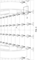
- the cameras 64, 66 therefore record the field below the vehicle 10, the plants 60 present there and the wheels 18, 20. Since the front and rear wheels 18, 20 usually run on the same track, ie not laterally offset from each other, it would basically be sufficient if the cameras 64, 66 only recorded the rear or front wheels 18, 20, although recording at least the contact points of all four wheels 18, 20 is preferred, as in the Figure 3 shown.
- the image angle of the cameras 64, 66 should be sufficiently large for this (super wide angle or fisheye or separate cameras for the left and right side).
- the image signal outputs of one or both of the cameras 64 and/or 66 are connected to the input and output unit 30 directly or via image processing systems 36 and the bus system 50. This makes it possible to display an image on the display unit 54 as shown in the Figure 3 is shown.
- the operator of the vehicle 10 is thus able to recognize whether the wheels 18, 20 drive over the plants 60 or not and to take suitable measures if necessary. In the case of purely manual steering of the vehicle 10 using the steering wheel 26, the operator can therefore countersteer accordingly or, in the case of automatic steering by the automatic steering system, switch this off and take over the steering himself using the steering wheel 26. If there is no automatic steering system and only the operator manages the steering of the vehicle using the steering wheel 26, the display unit 54 can help the operator to steer in such a way that no plants 60 are driven over.
- the image processing system 36 or the processor of the input and output unit 30 or the steering signal calculation unit 46 is therefore programmed to recognize plants 60 that have been driven over in the image of the camera 64 and/or 66. This can be done in such a way that in the image of the camera 64 and/or 66 it is recognized on the one hand at which lateral position at least the plants 60 adjacent to the wheels 18, 20 are located in the image, and on the other hand it is recognized at which lateral position in the image the tires of the wheels 18, 20 are located.
- the plants 60 can be identified using their usually green color and/or their shape and/or texture or the like, which applies analogously to the usually black color and/or rectangular and/or possibly studded shape of the tires, while a distinction from the field 58 is possible based on its position, texture and/or color. Any lateral overlap of the tires and the plants 60 can thus be easily recognized and used to generate a corresponding signal.
- the simultaneous detection of the wheels 18, 20 and their tires on the one hand and the rows of plants 60 on the other has the advantage that it is relatively easy to do and an overlap can be easily recognized, and that no image processing is required to detect damaged plants, as is in principle possible with a camera looking backwards or downwards from the vehicle 10 (not shown, but cf. the prior art according to EP 2 545 761 A1 , DE 10 2019 207 984 A1 , EP 4 140 238 A1 ), which does not include wheels 18, 20 and their tires, would be possible, but is more complicated and prone to errors.
- the signal from one or both of the cameras 64, 66 can supplement or replace the signal from the camera 32 of the visual sensor system 62, because the cameras 64 and/or 66 also provide the steering signal calculation unit 46 with information about the lateral position and orientation of the rows of plants 60 relative to the vehicle 10.
- the steering signal calculation unit 46 therefore receives information from the image processing systems 36 of the cameras 32 and 64 and/or 66 regarding the respectively detected lateral position and orientation of the rows of plants 60 relative to the vehicle 10 and a relative accuracy. If necessary, ie if in certain situations the signal from the camera 64 and/or 66 should be more accurate than that from the camera 32, e.g.
- the signal from the camera 64 and/or 66 is used to generate the steering signal, in particular in combination (after merging) with a lateral position and orientation of the rows of plants 60 relative to the vehicle 10 calculated on the basis of a stored path and the signal from the navigation unit 48.
- the disclosure of the patent application DE 10 2023 119 302.3 which is incorporated by reference into these documents.
- the associated image processing system 36 can provide three-dimensional point cloud information of the environment (ie the area in front of the vehicle 10). A subset of the three-dimensional points belonging to a representative area describing the slope of the terrain in front of the vehicle 10 can be identified.
- An ideal scenario would be an open field where every point detected belongs to the ground. In conditions with plants, some points belong to the plants 60 and some to the ground. Either points on the ground can be filtered out and used to adjust to a plane or all points are used so that the adjusted plane is an average, relative to the ground raised plane. In any case, this adjusted plane contains information about the inclination of the terrain (forward and sideways) with respect to a reference plane of the vehicle 10. It is therefore possible to recognize if the terrain in front of the vehicle is inclined with respect to the support plane of the vehicle 10.
- This inclination information from the stereo camera 32 (or an inclination taken from a map of the field) can be processed together with the signals from the camera 64 and/or 66, since nothing changes for the latter when the vehicle 10 is driving on an incline, since it always detects the ground beneath the vehicle 10 and the ground is therefore always horizontal for it. If the inclination of the field 58 should therefore change, the images from the camera 32 (or data for a stored path) can be combined with the signals from the camera 64 and/or 66 using the inclination of the terrain in front of the vehicle 10 in order to avoid steering errors, particularly in the transition area.
- the image processing system 36 of the camera 64 and/or 66 knows the three-dimensional shape of the field 58 in front of the vehicle 10 and can thus avoid possible errors in the signals of the camera 64 and/or 66 that could arise if the slope of the terrain and thus also of the vehicle 10 changes.
- the steering of the vehicle 10 based on the visual steering system 62 in the prior art is based on the fact that the target path 74 to be traveled is extrapolated to a reference point of the vehicle 10, which can in particular be the rear axle of the vehicle 10 (cf. US 6 445 983 B1 ).
- a reference point of the vehicle 10 can in particular be the rear axle of the vehicle 10 (cf. US 6 445 983 B1 ).
- This is problematic when (e.g. after the vehicle 10 has been parked) a first image is recorded again, which is then extrapolated to a position below the rear axle of the vehicle 10 using a stored data set, regardless of the actual movement of the vehicle 10 or even when the vehicle is at a standstill, and is later corrected using the images recorded thereafter.
- the camera 64 and/or 66 can be used (independently of or in addition to any detection of plants that have been driven over) to replace or modify the stored data set in order to align the path generated by the visual steering system 62 to the reference point, in particular the rear axle, of the vehicle 10 with the rows of plants 60 detected below the vehicle 10 and thus make it more precise. This can improve steering based on the rows of plants if the vehicle 10 is stopped for a time, in particular when driving over a curved row of plants, and later resumes operation.
- the part of the target path 74 which is located immediately in front of the vehicle 10, i.e., to the rear of the field of view of the visual steering system 62, and below the vehicle 10, is created on the basis of the signals from the camera 64 and/or 66 when (re-)starting an automatic steering process based on the visual steering system 62.
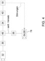
- the steering signal calculation unit 46 in the event of a The detection of overrun plants 60 in the manner described above causes the respective target path 74, on which the steering signal to the steering control 34 is based, to be shifted in a lateral direction in order to avoid overrunning plants 60.
- the signal from the camera 64 and/or 66 therefore serves as a feedback signal to the steering signal calculation unit 46, as in the Figure 4 is shown schematically. Disturbances that can be caused, for example, by a lateral slope that causes the vehicle 10 to deviate to the left or right and are not detected at least in the case of steering based only on the visual sensor system 62, are corrected in this way. Other possible disturbances can be slippage of the wheels 18, 20, or errors in the visual sensor system 62 or in the stored target path on which steering based on the navigation unit 48 is based.
- the area observed by the camera 64 (ie the rear wheels 20) and the position of the navigation unit 48 in the forward direction of the vehicle 10 are relatively close to each other and also to the control point of the vehicle 10 (which is used to generate the steering signal, cf. US 6 455 983 B1 ) located in the center of the rear axle. In this way, any errors between optically detected features and the vehicle position and orientation detected by the navigation unit 48 due to offsets in the forward direction are reduced or avoided.
Landscapes
- Life Sciences & Earth Sciences (AREA)
- Engineering & Computer Science (AREA)
- Mechanical Engineering (AREA)
- Soil Sciences (AREA)
- Environmental Sciences (AREA)
- Physics & Mathematics (AREA)
- General Physics & Mathematics (AREA)
- Multimedia (AREA)
- Theoretical Computer Science (AREA)
- Control Of Position, Course, Altitude, Or Attitude Of Moving Bodies (AREA)
- Guiding Agricultural Machines (AREA)
Applications Claiming Priority (1)
| Application Number | Priority Date | Filing Date | Title |
|---|---|---|---|
| DE102023120383.5A DE102023120383A1 (de) | 2023-08-01 | 2023-08-01 | Anordnung zur Erkennung einer eventuellen Abweichung eines landwirtschaftlichen Fahrzeugs von einem Sollweg bei einer Bearbeitung von in Reihen angebauten Pflanzen, entsprechendes Fahrzeug und Verfahren |
Publications (1)
| Publication Number | Publication Date |
|---|---|
| EP4501090A1 true EP4501090A1 (fr) | 2025-02-05 |
Family
ID=91758799
Family Applications (1)
| Application Number | Title | Priority Date | Filing Date |
|---|---|---|---|
| EP24185178.1A Pending EP4501090A1 (fr) | 2023-08-01 | 2024-06-28 | Système de détection d'un écart éventuel d'un véhicule agricole à partir d'une voie de consigne lors d'un traitement de plantes placées en rangées, véhicule et véhicule correspondants |
Country Status (4)
| Country | Link |
|---|---|
| US (1) | US20250040464A1 (fr) |
| EP (1) | EP4501090A1 (fr) |
| AU (1) | AU2024204428A1 (fr) |
| DE (1) | DE102023120383A1 (fr) |
Citations (16)
| Publication number | Priority date | Publication date | Assignee | Title |
|---|---|---|---|---|
| US6445983B1 (en) | 2000-07-07 | 2002-09-03 | Case Corporation | Sensor-fusion navigator for automated guidance of off-road vehicles |
| US6455983B2 (en) | 1998-04-17 | 2002-09-24 | Koninklijke Philips Electronics N.V. | Piezoelectric motor |
| EP1266553A2 (fr) | 2001-06-16 | 2002-12-18 | Deere & Company | Dispositif de direction automatique pour véhicule de travail agricole |
| EP1321037A2 (fr) | 2001-12-19 | 2003-06-25 | Deere & Company | Système de compensation automatique de la dérive due au vent pour un appareil de pulvérisation agricole |
| WO2008150418A1 (fr) | 2007-05-31 | 2008-12-11 | Deere & Company | Procédé et système de guidage de véhicule à ajustement fondé sur la vision |
| EP2545761A1 (fr) | 2011-07-12 | 2013-01-16 | CLAAS Selbstfahrende Erntemaschinen GmbH | Procédé de fonctionnement d'une moissonneuse automobile |
| WO2014105928A1 (fr) | 2012-12-28 | 2014-07-03 | Agco Corporation | Procédé et applications de système de coordonnées locales sur la base d'un flux de données optiques au moyen de caméras vidéo |
| DE102016209437A1 (de) | 2016-05-31 | 2017-11-30 | Deere & Company | Selbsttätiges Lenksystem zur Führung eines landwirtschaftlichen Fahrzeugs über ein Feld und entsprechendes Verfahren |
| WO2018067473A1 (fr) | 2016-10-03 | 2018-04-12 | Agjunction Llc | Utilisation de capteurs optiques pour résoudre des problèmes de cap de véhicule |
| DE102017217391A1 (de) * | 2017-09-29 | 2019-04-04 | Zf Friedrichshafen Ag | Landwirtschaftliches Arbeitsfahrzeug |
| US20190195824A1 (en) | 2017-12-19 | 2019-06-27 | Endress+Hauser Conducta Gmbh+Co. Kg | Reference electrode and method for manufacturing a reference electrode |
| DE102019207984A1 (de) | 2019-05-31 | 2020-12-03 | Deere & Company | Erntemaschine mit einem Sensor zur Überwachung des Stoppelbildes |
| EP4140238A1 (fr) | 2020-06-12 | 2023-03-01 | Fg Innovation Company Limited | Procédé de communication sans fil et équipement d'utilisateur pour transmission d'un prach ul |
| US20230060628A1 (en) * | 2021-08-30 | 2023-03-02 | Deere & Company | Agricultural machine map-based control system with position error rectification |
| US20230229163A1 (en) * | 2021-11-24 | 2023-07-20 | Raven Industries, Inc. | Curvature sensing and guidance control system for an agricultural vehicle |
| DE102023119302A1 (de) | 2023-07-21 | 2025-01-23 | Deere & Company | Anordnung zur Führung eines landwirtschaftlichen Fahrzeugs über ein Feld mit Sensorfusion und entsprechendes Verfahren |
Family Cites Families (6)
| Publication number | Priority date | Publication date | Assignee | Title |
|---|---|---|---|---|
| US20120226548A1 (en) * | 2005-07-21 | 2012-09-06 | Hanna Nader G | Method for requesting, displaying, and facilitating placement of an advertisement in a computer network |
| US10104827B2 (en) * | 2015-07-08 | 2018-10-23 | The Royal Institution For The Advancement Of Learning/Mcgill University | Guidance system and steering control device for an agricultural vehicle |
| US10531603B2 (en) * | 2017-05-09 | 2020-01-14 | Cnh Industrial America Llc | Agricultural system |
| CA3009217A1 (fr) * | 2017-06-22 | 2018-12-22 | 360 Yield Center, Llc | Systeme de direction automatisee ameliore destine a un vehicule |
| EP4095643A1 (fr) * | 2021-05-28 | 2022-11-30 | Agco Corporation | Systèmes de guidage de rangée de culture |
| JP2025002839A (ja) * | 2023-06-23 | 2025-01-09 | 株式会社クボタ | 列検出システムおよび農業機械 |
-
2023
- 2023-08-01 DE DE102023120383.5A patent/DE102023120383A1/de active Pending
-
2024
- 2024-06-27 AU AU2024204428A patent/AU2024204428A1/en active Pending
- 2024-06-28 EP EP24185178.1A patent/EP4501090A1/fr active Pending
- 2024-07-30 US US18/788,374 patent/US20250040464A1/en active Pending
Patent Citations (16)
| Publication number | Priority date | Publication date | Assignee | Title |
|---|---|---|---|---|
| US6455983B2 (en) | 1998-04-17 | 2002-09-24 | Koninklijke Philips Electronics N.V. | Piezoelectric motor |
| US6445983B1 (en) | 2000-07-07 | 2002-09-03 | Case Corporation | Sensor-fusion navigator for automated guidance of off-road vehicles |
| EP1266553A2 (fr) | 2001-06-16 | 2002-12-18 | Deere & Company | Dispositif de direction automatique pour véhicule de travail agricole |
| EP1321037A2 (fr) | 2001-12-19 | 2003-06-25 | Deere & Company | Système de compensation automatique de la dérive due au vent pour un appareil de pulvérisation agricole |
| WO2008150418A1 (fr) | 2007-05-31 | 2008-12-11 | Deere & Company | Procédé et système de guidage de véhicule à ajustement fondé sur la vision |
| EP2545761A1 (fr) | 2011-07-12 | 2013-01-16 | CLAAS Selbstfahrende Erntemaschinen GmbH | Procédé de fonctionnement d'une moissonneuse automobile |
| WO2014105928A1 (fr) | 2012-12-28 | 2014-07-03 | Agco Corporation | Procédé et applications de système de coordonnées locales sur la base d'un flux de données optiques au moyen de caméras vidéo |
| DE102016209437A1 (de) | 2016-05-31 | 2017-11-30 | Deere & Company | Selbsttätiges Lenksystem zur Führung eines landwirtschaftlichen Fahrzeugs über ein Feld und entsprechendes Verfahren |
| WO2018067473A1 (fr) | 2016-10-03 | 2018-04-12 | Agjunction Llc | Utilisation de capteurs optiques pour résoudre des problèmes de cap de véhicule |
| DE102017217391A1 (de) * | 2017-09-29 | 2019-04-04 | Zf Friedrichshafen Ag | Landwirtschaftliches Arbeitsfahrzeug |
| US20190195824A1 (en) | 2017-12-19 | 2019-06-27 | Endress+Hauser Conducta Gmbh+Co. Kg | Reference electrode and method for manufacturing a reference electrode |
| DE102019207984A1 (de) | 2019-05-31 | 2020-12-03 | Deere & Company | Erntemaschine mit einem Sensor zur Überwachung des Stoppelbildes |
| EP4140238A1 (fr) | 2020-06-12 | 2023-03-01 | Fg Innovation Company Limited | Procédé de communication sans fil et équipement d'utilisateur pour transmission d'un prach ul |
| US20230060628A1 (en) * | 2021-08-30 | 2023-03-02 | Deere & Company | Agricultural machine map-based control system with position error rectification |
| US20230229163A1 (en) * | 2021-11-24 | 2023-07-20 | Raven Industries, Inc. | Curvature sensing and guidance control system for an agricultural vehicle |
| DE102023119302A1 (de) | 2023-07-21 | 2025-01-23 | Deere & Company | Anordnung zur Führung eines landwirtschaftlichen Fahrzeugs über ein Feld mit Sensorfusion und entsprechendes Verfahren |
Non-Patent Citations (2)
| Title |
|---|
| "The International Federation for Information Processing", vol. 259, SPRINGER |
| WAN, X.LIU, G.: "Computer and Computing Technologies in Agriculture", vol. II, 2008, article "Automatic Navigation System with Multiple Sensors" |
Also Published As
| Publication number | Publication date |
|---|---|
| US20250040464A1 (en) | 2025-02-06 |
| DE102023120383A1 (de) | 2025-02-06 |
| AU2024204428A1 (en) | 2025-02-20 |
Similar Documents
| Publication | Publication Date | Title |
|---|---|---|
| DE10129135B4 (de) | Einrichtung zur Positionsbestimmung eines landwirtschaftlichen Arbeitsfahrzeugs sowie ein landwirtschaftliches Arbeitsfahrzeug mit dieser | |
| EP1419683B1 (fr) | Methode de commande d'un vehicule agricole | |
| US20200288625A1 (en) | Agricultural utility vehicle | |
| DE10129133A1 (de) | Einrichtung zur selbsttätigen Lenkung eines landwirtschaftlichen Arbeitsfahrzeugs | |
| DE102016209437B4 (de) | Selbsttätiges Lenksystem zur Führung eines landwirtschaftlichen Fahrzeugs über ein Feld und entsprechendes Verfahren | |
| EP2636292A1 (fr) | Agencement et procédé destiné à l'ensemencement de graines | |
| DE102020127084A1 (de) | Fahrzeugverbindungsleitsystem | |
| EP3756433B1 (fr) | Système de commande d'un outil de travail raccordé à un véhicule | |
| EP1266554A2 (fr) | Dispositif de direction automatique pour véhicule de travail agricole | |
| EP1475609B1 (fr) | Système de compensation d'un système de référence d'un véhicule terrestre | |
| DE102022207537A1 (de) | Kartenbasiertes steuersystem mit positionsfehlerkorrektur für landwirtschaftliche maschinen | |
| DE102019203247A1 (de) | Vision-basiertes Lenkungsassistenzsystem für Landfahrzeuge | |
| DE102016212201A1 (de) | Anordnung zur selbsttätigen Führung eines Gerätes | |
| DE102011051827A1 (de) | Landwirtschaftliche Arbeitsmaschine mit einer Einrichtung zur Erfassung von deren Fahrzeugzuständen | |
| EP4085741A1 (fr) | Procédé de direction pour une machine agricole | |
| EP4401046A1 (fr) | Dispositif de détection de la position d'un conteneur de chargement basé sur une image | |
| EP1847898B1 (fr) | Procédé d'enregistrement de données représentant le chemin emprunté par une machine agricole | |
| DE102019203651A1 (de) | System zur selbsttätigen Lenkung eines Fahrzeugs | |
| DE102023119302A1 (de) | Anordnung zur Führung eines landwirtschaftlichen Fahrzeugs über ein Feld mit Sensorfusion und entsprechendes Verfahren | |
| EP4501090A1 (fr) | Système de détection d'un écart éventuel d'un véhicule agricole à partir d'une voie de consigne lors d'un traitement de plantes placées en rangées, véhicule et véhicule correspondants | |
| DE102023119096A1 (de) | Verfahren zur Kalibrierung der Positionierung und/oder Ausrichtung eines an einem landwirtschaftlichen Fahrzeug angebrachten optischen Erfassungssystems und entsprechende Anordnung | |
| DE102021125360A1 (de) | Vorrichtung und Verfahren zur Bestimmung einer Lenkvorgabe für eine landwirtschaftliche Maschine | |
| EP1688027B1 (fr) | Véhicule agricole à direction automatique | |
| DE102017126512A1 (de) | Dynamikregelungssystem für ein selbstfahrendes Fahrzeug | |
| US20230419544A1 (en) | Methods of Locating Agricultural Implements |
Legal Events
| Date | Code | Title | Description |
|---|---|---|---|
| PUAI | Public reference made under article 153(3) epc to a published international application that has entered the european phase |
Free format text: ORIGINAL CODE: 0009012 |
|
| STAA | Information on the status of an ep patent application or granted ep patent |
Free format text: STATUS: THE APPLICATION HAS BEEN PUBLISHED |
|
| AK | Designated contracting states |
Kind code of ref document: A1 Designated state(s): AL AT BE BG CH CY CZ DE DK EE ES FI FR GB GR HR HU IE IS IT LI LT LU LV MC ME MK MT NL NO PL PT RO RS SE SI SK SM TR |
|
| STAA | Information on the status of an ep patent application or granted ep patent |
Free format text: STATUS: REQUEST FOR EXAMINATION WAS MADE |
|
| 17P | Request for examination filed |
Effective date: 20250805 |