EP4501099A1 - Machine de récolte - Google Patents
Machine de récolte Download PDFInfo
- Publication number
- EP4501099A1 EP4501099A1 EP24176990.0A EP24176990A EP4501099A1 EP 4501099 A1 EP4501099 A1 EP 4501099A1 EP 24176990 A EP24176990 A EP 24176990A EP 4501099 A1 EP4501099 A1 EP 4501099A1
- Authority
- EP
- European Patent Office
- Prior art keywords
- harvesting machine
- crop
- cutting unit
- occupancy
- driving speed
- Prior art date
- Legal status (The legal status is an assumption and is not a legal conclusion. Google has not performed a legal analysis and makes no representation as to the accuracy of the status listed.)
- Pending
Links
Images



Classifications
-
- A—HUMAN NECESSITIES
- A01—AGRICULTURE; FORESTRY; ANIMAL HUSBANDRY; HUNTING; TRAPPING; FISHING
- A01D—HARVESTING; MOWING
- A01D41/00—Combines, i.e. harvesters or mowers combined with threshing devices
- A01D41/12—Details of combines
- A01D41/127—Control or measuring arrangements specially adapted for combines
- A01D41/1274—Control or measuring arrangements specially adapted for combines for drives
-
- A—HUMAN NECESSITIES
- A01—AGRICULTURE; FORESTRY; ANIMAL HUSBANDRY; HUNTING; TRAPPING; FISHING
- A01D—HARVESTING; MOWING
- A01D41/00—Combines, i.e. harvesters or mowers combined with threshing devices
- A01D41/12—Details of combines
- A01D41/127—Control or measuring arrangements specially adapted for combines
- A01D41/1271—Control or measuring arrangements specially adapted for combines for measuring crop flow
-
- A—HUMAN NECESSITIES
- A01—AGRICULTURE; FORESTRY; ANIMAL HUSBANDRY; HUNTING; TRAPPING; FISHING
- A01D—HARVESTING; MOWING
- A01D75/00—Accessories for harvesters or mowers
- A01D75/18—Safety devices for parts of the machines
- A01D75/182—Avoiding overload
Definitions
- the harvesting machine which can in particular be a combine harvester or a forage harvester, comprises a drive for moving the harvesting machine at a driving speed across a field.
- the drive can, for example, comprise an internal combustion engine and a transmission.
- the drive is generally used to drive round tires and/or crawler tracks, by means of which the harvesting machine is moved on a surface.
- the harvesting machine further comprises a cutting unit for cutting the crop in the field.
- the cutting unit can in particular comprise a cutter bar which, when the harvesting machine is operated as intended, is guided a short distance above the ground and cuts the plants that make up the crop just above the ground.
- the cut crop is then typically moved in the direction of a central transfer opening of the cutting unit and transferred there to a downstream intake channel.
- the crop is transferred to downstream working elements of the harvesting machine via the intake channel.
- this can in particular be a threshing device, and in the case of a forage harvester, in particular a chopping device.
- the harvesting machine further comprises a sensor device which is provided and set up to record information relating to a crop throughput currently being processed by the harvesting machine.
- the sensor device can act in or on an intake channel of the harvesting machine in order to measure an entire crop flow conveyed from the cutting unit to downstream working elements.
- the sensor device can be formed, for example, by a layer height sensor, by means of which a layer height of a crop layer of a crop flow conveyed through the intake channel can be recorded.
- the harvesting machine further comprises a control system which is designed and set up to control the drive of the harvesting machine depending on the information recorded by the sensor device.
- This control is carried out in such a way that the driving speed of the harvesting machine is set to a desired target value by means of the control system.
- the control system selects a low driving speed for the harvesting machine when the crop throughput is high in order to reduce the crop throughput.
- the control system can increase the driving speed in order to operate the working elements of the harvesting machine close to their optimal operating point and in this way increase the efficiency of the harvesting process.
- the known method however, has the disadvantage that irregular geometries of the crop stock present in the respective field cannot be adequately taken into account.
- the present application is therefore based on the object of providing a harvesting machine which has a higher operational reliability than the prior art.
- the harvesting machine is characterized in that the control is provided and set up to receive, in addition to the information recorded by the sensor device regarding the crop throughput currently processed by the harvesting machine, further information relating to an expected header occupancy in front of the harvesting machine.
- the control is also provided and set up to control the travel drive depending on the expected header occupancy and thereby adjust the travel speed of the harvesting machine.
- the control therefore processes information of at least two different types, namely, on the one hand, information relating to the current crop throughput of the harvesting machine and, on the other hand, information relating to an expected header occupancy that will occur in the near future when the harvesting machine continues to travel as planned.
- the invention is therefore based on the idea that the crop throughput can change very quickly with a changing cutting unit occupancy, for example in the form of a sudden change when the cutting unit changes from partial occupancy to full occupancy. Such changes occur in principle independently of the density of the crop in the respective field and thus represent special effects that are not adequately taken into account in the prior art.
- the driving speed can be reduced in time so that the crop throughput in the harvester does not lead to an overload when the sudden increase in the cutting unit occupancy takes effect.
- the driving speed of the harvesting machine could only be determined based on the information from the sensor device regarding the current crop throughput.
- the sensor device for example in or on an intake channel.
- the result is downtime, possibly combined with repair work, which significantly reduces the productivity of the harvesting process.
- a scenario in which the harvester drives out of a crop stand and the edge of the stand is slanted is also important.
- the crop throughput decreases gradually when exiting, whereupon the control increases the driving speed to increase the crop throughput.
- the control recognizes that the header occupancy is decreasing to zero, i.e. the harvester is driving out of the stand. It then influences the control so that the driving speed is not increased beyond a preset value. In other words, the control limits the driving speed of the harvester when exiting a crop stand. This makes turning maneuvers on the headland of the respective field easier and therefore leads to increased comfort for the machine operator.
- the harvesting machine comprises at least one detection device that is designed and configured to detect information relating to a crop stock present in the field in front of the harvesting machine.
- the detection device can be used to directly or indirectly detect the information that is made available to the control system in accordance with the above description in order to control the travel drive depending on the expected header occupancy in order to adjust the travel speed.
- the detection device can comprise a receiving device that is set up to detect signals for satellite-based location determination.
- the receiving device can be set up to receive location signals from the GPS system, the Galileo system and/or other satellite systems for location determination.
- This information allows the control system to access inventory maps that depict the field to be worked on, i.e., in particular, provide information about the geometry of a crop edge of the crop.
- the control system can evaluate where the harvester is located in relation to the crop and how the crop behaves, and in particular changes, in front of the harvester when the harvester continues to travel as intended. Any sudden change in the cutting unit occupancy of the harvester's cutting unit can be detected early on in this way, so that the control system can control the drive to adjust the travel speed.
- the detection device can comprise a sensor unit that is intended and set up to detect information on the expected header occupancy of the header that is to be expected when the harvesting machine continues to travel as planned.
- a sensor unit can, for example, comprise at least one LIDAR system that is set up to detect the area in front of the harvesting machine.
- This system can in particular comprise at least one laser, at least one scanner and at least one detector, wherein laser beams are generated in a manner known per se by means of the laser, which are distributed within an observation area by means of the scanner, wherein the laser beams are reflected by objects within the observation area and these reflections are registered by the detector.
- a three-dimensional image of the observation area which includes the area in front of the harvesting machine, can be created using a time-of-flight measurement.
- information is available that can be used to assess the header occupancy in front of the harvesting machine.
- the control system can determine the expected header occupancy that will soon be present at the header if the harvester continues to travel as planned. Accordingly, it is possible for the control system to control the drive of the harvester to adjust the driving speed to the expected header occupancy.
- the sensor unit can comprise at least one camera that is set up for optical detection of the area in front of the harvesting machine.
- information can be continuously recorded in the form of image information, which can be determined, for example, by means of a Image analysis can be used to evaluate the results.
- image analysis can provide information about whether the header occupancy will soon change if the harvester continues to travel as planned, so that the control system can react to this in the manner described and control the drive to adjust the driving speed.
- the information recorded by the recording device can be passed on to the controller and/or a separate processing unit so that the information can be processed by the controller or the processing unit.
- the recorded information can be converted or processed into other information if required, which the controller can use to assess the expected header occupancy.
- the transfer of information from the recording device to the controller can therefore take place directly or indirectly, with a detour via a processing unit being provided if necessary in order to first bring the information recorded by the recording device into a form that can be processed by the controller.
- a processing unit can, for example, be arranged externally, i.e. away from the harvesting machine itself, with information being transmitted from the recording device to the processing unit, for example, wirelessly via the mobile network or the Internet.
- the sensor device for detecting information regarding the crop throughput currently being processed by the harvesting machine interacts with an intake channel of the harvesting machine.
- the crop throughput in the intake channel can be detected by means of the sensor device.
- the sensor device can comprise at least one layer height sensor, by means of which a layer height of a crop layer of the crop that is conveyed through the intake channel can be detected. From the layer height of the crop layer and knowing the width of the intake channel, the crop throughput in the form of a mass flow (kg/s) or a volume flow (m 3 /s) can be determined as a result of continuous observation. This information from the sensor device is then used by the control system in the manner described to set the driving speed of the harvesting machine.
- FIG. 1 An example of implementation that can be found in the Figures 1 to 5 , comprises a harvesting machine 1 according to the invention, which in the example shown is formed by a self-propelled combine harvester.
- This comprises a drive 2, which in the example shown comprises an internal combustion engine and a transmission device operatively connected thereto.
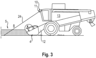
- the latter At a front end of the harvesting machine 1 in the direction of travel, the latter comprises a cutting unit 4, which is set up with a cutter bar 22 for cutting off crop 5 standing on a field 3.
- cut crop 5 is guided into an intake channel 12 , which is sometimes also referred to as an inclined conveyor.
- the intake channel 12 By means of the intake channel 12, the crop 5 or the crop stream formed therefrom is guided to downstream working elements.
- the crop flow first reaches a threshing device 21, by means of which the fruits of the crop 5 are separated from plant residues.
- a large part of the separated fruits are separated by a threshing concave of the threshing device 21 onto a preparation floor 20 , from which the fruits are fed to a sieving device 18.
- This comprises two sieves 19, namely an upper sieve and a lower sieve.
- a remaining part of the fruits separated in the threshing device 21 is transferred together with the plant residues to a separating device, which in the example shown is formed by a separating rotor 14.
- the remaining fruits are separated from the plant residues by means of the separating rotor 14.
- the plant residues are finally fed to a rear-side chopper 16 of the harvesting machine 1 , by means of which they are chopped and finally ejected from the rear via a radial fan 17 .
- the fruits separated by means of the separating rotor 14 are guided downwards to a return floor 15 , from where they are fed to the preparation floor 20 and finally also to the screening device 18.
- the screened fruits are finally conveyed into a grain tank 13 and stored there.
- the combine harvester 1 further comprises a control 7, which is designed and configured to control the drive 2. This is done in such a way that the driving speed of the harvesting machine 1 is automatically set and should assume a determined target value.
- This target value is initially determined based on the crop throughput that is currently being processed in the harvesting machine 1.
- the harvesting machine 1 has a sensor device 6. In the example shown, this is arranged in the intake channel 12 and comprises a layer height sensor. This is suitable for recording a layer height of a crop layer conveyed in the intake channel 12 , wherein the crop flow can be determined by recording this value over time.
- the basic principle for controlling the drive 2 by means of the controller 7 is that the crop flow should be as close as possible to a predetermined range at which - possibly depending on other harvesting parameters and/or environmental parameters - the harvesting machine 1 is at an optimal operating point. If the current crop throughput is below the predetermined range, the controller 7 controls the drive 2 in such a way that the driving speed of the harvesting machine 1 is increased. The intention here is to collect a larger amount of crop 5 within a given period of time so that the crop flow increases and is ultimately within the predetermined range. Conversely, if the current crop throughput is above the predetermined range, the driving speed can be automatically reduced.
- This type of operation of the combine harvester 1 is appropriate for the normal case of a full header occupancy of the header 4.
- the header 4 is only partially occupied, i.e. crop 5 is only present in the field 3 in front of the harvesting machine 1 on part of the width of the header 4 , in certain situations the working elements of the harvesting machine 1 may be overloaded.
- the risk of such an overload is in particular that starting from a partial occupancy of the header 4, the latter increases significantly over a particularly short distance traveled by the harvesting machine 1. This may be the case, for example, with a sloping crop edge 23 of the respective crop at one edge of the respective field 3. It is also conceivable that the crop edge 23 has a "stepped" shape, as a result of which the occupancy of the header 4 can suddenly increase at a certain point.
- Relevant examples can be found in the Figures 4 and 5 , which are explained separately below.
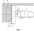
- the harvesting machine 1 comprises a detection device 9, by means of which information can be detected regarding a crop stock located in the area 8 in front of the harvesting machine 1 on the field 3.
- the information detected by the detection device 9 is sent to the control 7 and received by it, so that the control 7 can use this additional information.
- information is available regarding which cutting unit occupancy of the cutting unit 4 is to be expected in the near future if the harvesting machine 1 continues to travel as planned.
- the information accordingly relates to the expected cutting unit occupancy in the area 8 in front of the harvesting machine 1. This enables the control 7 to control the drive depending on this expected cutting unit occupancy so that the driving speed of the harvesting machine is adjusted.
- this adjustment generally consists of a reduction in the driving speed.
- the driving speed can be reduced at a time when the (possibly sudden) change in the cutting unit occupancy has not yet manifested itself in the form of a current crop throughput in the intake channel 12. If this had to be waited for and the control system 7 could only react when the current crop throughput in the intake channel 12 suddenly increased, an overload of the downstream working elements of the harvesting machine 1 would be difficult or impossible to avoid.
- the detection device comprises both a receiving device 10 and a sensor unit 11.
- the receiving device 10 is intended and set up to receive signals for satellite-based location determination, so that a global position of the harvesting machine 1 can be determined by means of the receiving device 10.
- the location of the harvesting machine 1 at a particular point in time can then be compared using available inventory maps, so that it can be determined, for example, whether the harvesting machine 1 is moving along a sloping or stepped crop edge 23. By comparing this data, it is possible to predict which cutting unit occupancy of the harvesting machine 1 can be expected when the journey continues as planned.
- the additional sensor unit 11 comprises a LIDAR system in the example shown, by means of which an observation area 24 in front of the harvesting machine 1 can be observed. This is shown by the Figures 2 and 3 illustrated, wherein the observation area 24 can extend, for example, linearly over a width of the cutting unit 4 at a certain distance in front of the harvesting machine 1 in the apron 8.
- the sensor unit 11 can detect how the crop stock on the field 3 in front of the harvesting machine 1 develops or changes, so that the expected cutting unit occupancy of the cutting unit 4 can be determined.
- FIG 4 A field 3 with a crop on it is schematically illustrated in a top view.
- the harvesting machine 1 enters the crop at a left end of the field 3 at a time t0.
- the driving speed of the harvesting machine 1 which is shown in a lower diagram in Figure 4 illustrated by a speed axis 26 plotted against a time axis 27 , is initially at a low first level when it enters the crop stock.
- the first cut crop 5 reaches the intake channel 12, so that an increase in the layer height of the crop layer conveyed in the intake channel 12 is determined by means of the sensor device 6.
- This is shown by the Figure 4 upper diagram, which plots the measured layer height on a layer height axis 25 against the time axis 27.
- the layer height initially continues to rise as the harvesting machine 1 continues to travel as planned.
- the layer height as such and its increase over time are to be assessed as low overall, so that the control automatically controls the drive to increase the driving speed in order to increase productivity. Accordingly, the driving speed is increased between times t1 and t2 starting from the first level to a second, higher level.
- the measured layer height in the intake channel 12 is rapidly developed in the direction of a predetermined maximum value 28 , with which safe operation of the working elements of the harvesting machine 1 is still possible. Approaching this maximum value 28 is advantageous for exploiting productivity.
- the driving speed has reached a value by means of which the layer height will foreseeably increase to a desired value.
- This driving speed therefore represents the target value for the driving speed until further notice.
- the desired value of the layer height is reached approximately at time t3.
- the harvester 1 is therefore driven at the driving speed on the second level until continued until further notice.
- a change in the crop stock is finally registered by means of the detection device 9 in the forecourt 8 of the harvesting machine 1. This leads to the expectation that the cutting unit occupancy of the cutting unit 4 will soon increase if the harvesting machine 1 continues to travel as planned. In the example shown, the crop edge 23 of the crop stock is stepped, so that a sudden increase in the cutting unit occupancy is expected.
- the cutting unit occupancy will develop from approximately half occupancy to full occupancy.
- the detection device 9 also shows how far in the forecourt 8 in front of the harvesting machine 1 the change in the cutting unit occupancy is to be expected. Knowing the driving speed of the harvesting machine 1 , the time at which the cutting unit occupancy will change can thus be determined. This time is shown in the diagrams in Figure 4 on the time axis 27 marked t5.
- the controller 7 controls the drive 2 of the harvesting machine so that the driving speed of the harvesting machine 1 is adjusted, namely reduced.
- This reduction in driving speed already takes place before the sudden increase in the cutting unit occupancy occurs. Accordingly, the driving speed is reduced in a period between times t4 and t5.
- This initially has no effect on the layer height measured in the intake channel 12 , since a change in the driving speed only has a delayed effect there.
- the crop 5 cut off in each case must first be brought together in the cutting unit 4 in the middle at the height of the intake channel 12 and transferred to the intake channel 12 .
- the reduction in the driving speed at time t4 is then noticeable in a decrease in the layer height in the intake channel 12 from time t5.
- the layer height in the intake channel 12 increases again from time t6 despite the speed remaining the same.
- the driving speed is specified by the control system 7 from time t5 in such a way that, taking into account the increase in the cutting unit occupancy, the layer height in the intake channel 12 is again close to the maximum value 28. In this way, by means of the control system 7 in conjunction with the sensor device 6 and the detection device 9, an overload of the working elements of the harvesting machine 1 could be avoided, while the utilization of the harvesting machine 1 was kept at the highest possible level.
- the crop edge 23 is oriented obliquely with respect to a direction of travel of the harvesting machine 1. This means that when the harvesting machine 1 enters the crop crop on the field 3, the cutting unit occupancy gradually changes from zero to full cutting unit occupancy. If the driving speed of the harvesting machine 1 were controlled solely by detecting the layer height of the crop layer conveyed in the intake channel 12 , the driving speed would be continually increased due to the initially low cutting unit occupancy (and the resulting low layer height in the intake channel 12 ).
- the control system 7 can control the drive 2 to adjust the driving speed accordingly.
- the driving speed which is in Figure 5 in the lower diagram there is plotted on a speed axis 26 against a time axis 27 , starting from a first low level at a time t1 up to a time t2, whereby in the interest of a high productivity of the harvesting machine 1 the measured layer height in the intake channel 12 increases increasingly rapidly.
- This is shown in the upper diagram in Figure 5 illustrates that the layer height is plotted on a layer height axis 25 against the time axis 27.
- the driving speed is adjusted so that it is not increased any further. Instead, it is kept at least essentially constant until time t3, while the layer height continues to rise significantly over the same period due to the delay described.
- the effect of the lack of further acceleration of the harvesting machine 1 on the layer height becomes apparent from time t3, from which the layer height does continue to rise, but this is no longer due to an acceleration of the harvesting machine 1, but only due to the increasing cutting unit occupancy of the cutting unit 4 .
- the driving speed is gradually reduced by means of the control 7 from time t3 in order to counteract the increasing cutting unit occupancy and thereby prevent the crop throughput from increasing to too high a value. From time t4, at which the cutting unit occupancy has reached its maximum, the driving speed is kept constant. The layer height in the intake channel 12 increases slightly after time t4, which is delayed by the previous remaining increase in the cutting unit occupancy. Finally, the layer height in the intake channel 12 reaches its highest value close to the maximum value 28. The harvesting machine 1 then runs with optimum productivity. Overloading of the working elements could be avoided by predictively reducing the driving speed in knowledge of the expected header utilization.
Landscapes
- Life Sciences & Earth Sciences (AREA)
- Environmental Sciences (AREA)
- Harvester Elements (AREA)
- Combines (AREA)
Applications Claiming Priority (1)
| Application Number | Priority Date | Filing Date | Title |
|---|---|---|---|
| DE102023120264.2A DE102023120264A1 (de) | 2023-07-31 | 2023-07-31 | Erntemaschine |
Publications (1)
| Publication Number | Publication Date |
|---|---|
| EP4501099A1 true EP4501099A1 (fr) | 2025-02-05 |
Family
ID=91193481
Family Applications (1)
| Application Number | Title | Priority Date | Filing Date |
|---|---|---|---|
| EP24176990.0A Pending EP4501099A1 (fr) | 2023-07-31 | 2024-05-21 | Machine de récolte |
Country Status (2)
| Country | Link |
|---|---|
| EP (1) | EP4501099A1 (fr) |
| DE (1) | DE102023120264A1 (fr) |
Citations (5)
| Publication number | Priority date | Publication date | Assignee | Title |
|---|---|---|---|---|
| DE10130665A1 (de) * | 2001-06-28 | 2003-01-23 | Deere & Co | Vorrichtung zur Messung der Menge von auf einem Feld stehenden Pflanzen |
| DE102011085380A1 (de) * | 2011-10-28 | 2013-05-02 | Deere & Company | Anordnung und Verfahren zur vorausschauenden Untersuchung von mit einer Erntemaschine aufzunehmenden Pflanzen |
| DE102013209197A1 (de) | 2013-05-17 | 2014-11-20 | Deere & Company | Erntemaschine mit vorausschauender Vortriebsgeschwindigkeitsregelung |
| WO2016040960A1 (fr) * | 2014-09-12 | 2016-03-17 | Appareo System, Llc | Capteur de qualité de grain non fondé sur image |
| EP4136956A1 (fr) * | 2021-08-17 | 2023-02-22 | CLAAS Selbstfahrende Erntemaschinen GmbH | Procédé de fonctionnement d'une machine de récolte automotrice et machine de récolte automotrice |
-
2023
- 2023-07-31 DE DE102023120264.2A patent/DE102023120264A1/de active Pending
-
2024
- 2024-05-21 EP EP24176990.0A patent/EP4501099A1/fr active Pending
Patent Citations (5)
| Publication number | Priority date | Publication date | Assignee | Title |
|---|---|---|---|---|
| DE10130665A1 (de) * | 2001-06-28 | 2003-01-23 | Deere & Co | Vorrichtung zur Messung der Menge von auf einem Feld stehenden Pflanzen |
| DE102011085380A1 (de) * | 2011-10-28 | 2013-05-02 | Deere & Company | Anordnung und Verfahren zur vorausschauenden Untersuchung von mit einer Erntemaschine aufzunehmenden Pflanzen |
| DE102013209197A1 (de) | 2013-05-17 | 2014-11-20 | Deere & Company | Erntemaschine mit vorausschauender Vortriebsgeschwindigkeitsregelung |
| WO2016040960A1 (fr) * | 2014-09-12 | 2016-03-17 | Appareo System, Llc | Capteur de qualité de grain non fondé sur image |
| EP4136956A1 (fr) * | 2021-08-17 | 2023-02-22 | CLAAS Selbstfahrende Erntemaschinen GmbH | Procédé de fonctionnement d'une machine de récolte automotrice et machine de récolte automotrice |
Also Published As
| Publication number | Publication date |
|---|---|
| DE102023120264A1 (de) | 2025-02-06 |
Similar Documents
| Publication | Publication Date | Title |
|---|---|---|
| EP2921042B1 (fr) | Moissonneuse dotée d'un réglage de la vitesse de propulsion anticipé | |
| EP1645178B1 (fr) | Système d'assistance pour le transfert | |
| EP3533315B2 (fr) | Récolteuse-hacheuse-chargeuse de fourrage et procédé de fonctionnement d'une récolteuse-hacheuse-chargeuse de fourrage | |
| EP2586286B1 (fr) | Agencement et procédé destinés à l'examen prévisionnel de plantes récoltées avec une moissonneuse | |
| EP2803256B1 (fr) | Moissonneuse dotée d'un réglage de la vitesse de propulsion anticipé | |
| EP1408732B1 (fr) | Dispositif de distribution con u pour des produits haches issus d'une recolteuse | |
| EP3494771B1 (fr) | Dispositif de hauteur de coupe automatique | |
| EP3424292B1 (fr) | Procédé d'analyse de l'état de fonctionnement d'une barre de coupe et barre de coupe | |
| BE1025641B1 (de) | Steueranordnung für eine Schleifeinrichtung und/oder Einrichtung zur Einstellung der Position einer Gegenschneide eines Feldhäckslers | |
| DE102014208068A1 (de) | Erntemaschine mit sensorbasierter Einstellung eines Arbeitsparameters | |
| DE102015118767A1 (de) | Umfelddetektionseinrichtung für landwirtschaftliche Arbeitsmaschine | |
| EP1609349A1 (fr) | Moissonneuse automotrice | |
| BE1029377B1 (de) | Feldhäcksler mit vorausschauender Ansteuerung des Bearbeitungsgrads eines Körnerprozessors | |
| EP2218320B1 (fr) | Ramasseuse-hacheuse dotée d'un dispositif de traitement et de transport de marchandises à réglage couplé | |
| EP3530101A1 (fr) | Récolteuse-hacheuse-chargeuse de fourrage automotrice | |
| EP4218394A1 (fr) | Ramasseuse-hacheuse automotrice et procédé de fonctionnement d'une ramasseuse-hacheuse automotrice | |
| EP4252519A1 (fr) | Moissonneuse agricole et procédé de commande d'une moissonneuse agricole | |
| EP4501099A1 (fr) | Machine de récolte | |
| EP4410089A1 (fr) | Moissonneuse agricole automotrice | |
| EP4154697B1 (fr) | Système d'aide à la conduite d'un engin d'abattage-façonnage pourvu de mécanisme de coupe de bande | |
| EP4154700A1 (fr) | Engin d'abattage-façonnage pourvu de mécanisme de coupe de bande | |
| EP2108248B1 (fr) | Ramasseuse-hacheuse et dispositif d'introduction pour une ramasseuse-hacheuse | |
| EP4529757A1 (fr) | Procédé de commande d'au moins une machine de travail agricole autopropulsée | |
| DE102023102284A1 (de) | Selbstfahrende landwirtschaftliche Erntemaschine | |
| EP4434315A1 (fr) | Attelage agricole pour véhicules destiné à faucher des fourrages |
Legal Events
| Date | Code | Title | Description |
|---|---|---|---|
| PUAI | Public reference made under article 153(3) epc to a published international application that has entered the european phase |
Free format text: ORIGINAL CODE: 0009012 |
|
| STAA | Information on the status of an ep patent application or granted ep patent |
Free format text: STATUS: THE APPLICATION HAS BEEN PUBLISHED |
|
| AK | Designated contracting states |
Kind code of ref document: A1 Designated state(s): AL AT BE BG CH CY CZ DE DK EE ES FI FR GB GR HR HU IE IS IT LI LT LU LV MC ME MK MT NL NO PL PT RO RS SE SI SK SM TR |
|
| P01 | Opt-out of the competence of the unified patent court (upc) registered |
Free format text: CASE NUMBER: APP_6306/2025 Effective date: 20250206 |
|
| STAA | Information on the status of an ep patent application or granted ep patent |
Free format text: STATUS: REQUEST FOR EXAMINATION WAS MADE |
|
| 17P | Request for examination filed |
Effective date: 20250805 |