EP4501157A1 - Umkehrbarer ledergürtel - Google Patents
Umkehrbarer ledergürtel Download PDFInfo
- Publication number
- EP4501157A1 EP4501157A1 EP24188902.1A EP24188902A EP4501157A1 EP 4501157 A1 EP4501157 A1 EP 4501157A1 EP 24188902 A EP24188902 A EP 24188902A EP 4501157 A1 EP4501157 A1 EP 4501157A1
- Authority
- EP
- European Patent Office
- Prior art keywords
- ribbon
- face
- leather goods
- strip
- width
- Prior art date
- Legal status (The legal status is an assumption and is not a legal conclusion. Google has not performed a legal analysis and makes no representation as to the accuracy of the status listed.)
- Granted
Links
Images

Classifications
-
- A—HUMAN NECESSITIES
- A41—WEARING APPAREL
- A41F—GARMENT FASTENINGS; SUSPENDERS
- A41F9/00—Belts, girdles, or waistbands for trousers or skirts
- A41F9/002—Free belts
-
- A—HUMAN NECESSITIES
- A41—WEARING APPAREL
- A41F—GARMENT FASTENINGS; SUSPENDERS
- A41F9/00—Belts, girdles, or waistbands for trousers or skirts
- A41F9/02—Expansible or adjustable belts or girdles ; Adjustable fasteners comprising a track and a slide member
- A41F9/025—Adjustable belts or girdles
-
- A—HUMAN NECESSITIES
- A41—WEARING APPAREL
- A41D—OUTERWEAR; PROTECTIVE GARMENTS; ACCESSORIES
- A41D15/00—Convertible garments
- A41D15/005—Convertible garments reversible garments
-
- A—HUMAN NECESSITIES
- A41—WEARING APPAREL
- A41D—OUTERWEAR; PROTECTIVE GARMENTS; ACCESSORIES
- A41D2200/00—Components of garments
- A41D2200/10—Belts
Definitions
- the invention relates to a leather goods belt.
- a belt generally comprises a ribbon having a first face and a second face opposite the first face, the ribbon having a predetermined length and extending between a first folded end and a second unfolded end which is opposite the first folded end.
- Such a belt also includes a belt closing mechanism formed by a buckle mechanically secured in rotation to the first folded end of the ribbon, and by a tongue mounted so as to be movable in rotation on the buckle at the first folded end of the ribbon.
- Such a belt further comprises a plurality of orifices arranged at a distance from each other according to a determined gap, opposite the buckle and the tongue, on the side of the second end, and provided to receive the tongue when the second end of the ribbon is inserted into the buckle so as to close the ribbon of the belt.
- Such a belt generally also includes one or more loops which are mounted on the ribbon, for example movable in a space delimited by the first folded end.
- Some belts are called reversible. This means that they can be worn with the first side visible or with the second side visible.
- the invention aims to provide a reversible leather goods belt, of the type described above, which is particularly simple and convenient both to manufacture and to use.
- the invention relates to a reversible leather goods belt comprising a ribbon having a first face and a second face opposite the first face, the ribbon having a determined length and extending between a first end and a second end opposite the first end, the ribbon having a slot extending from the first end and opening onto the first face and onto the second face, the reversible leather goods belt further comprising a loop mounted movable in translation on the ribbon, a buckle mechanically secured in rotation to the first end of the ribbon, and a tongue mechanically secured in rotation to the first end of the ribbon and movable relative to the buckle and through the slot; the reversible leather goods belt being characterized in that the first end of the ribbon is free and not folded, and the ribbon is provided with at least a first portion having a first width and at least a second thinned portion having a second width less than the first width, extending from the first free and unfolded end and joining the first portion, with the loop which is mounted movable in translation on the second thinned
- the tape may have a determined thickness over its determined length, formed of a first strip of material and a second strip of material arranged against each other and mechanically secured to each other, with the loop which is partially sandwiched between the first strip of material and the second strip of material, at the first free and unfolded end.
- the first strip of material and the second strip of material can be made as a single piece folded over on itself and the loop can be sandwiched at the fold.
- the first strip of material and the second strip of material may be distinct from each other and join at the first free and unfolded end of the ribbon by an addition of material at least partially covering the loop.
- the first strip of material and the second strip of material may be sewn together at edges of the tape and the slit may be at least partially surrounded by an additional stitching line.
- the first portion and the second thinned portion may join at a first junction portion having a variable width decreasing from the first portion toward the second thinned portion.
- the first joining portion may have a beveled edge or a curved edge.
- the first side of the ribbon may have a first pattern and/or a first shade and the second side of the ribbon may have a second pattern different from the first pattern and/or a second shade different from the first shade.
- the ribbon may comprise a plurality of through holes, which are provided opening onto the first face and onto the second face and at a distance from each other according to a determined gap from the second end, each through hole being configured to receive the tongue when the second end of the ribbon is inserted into the buckle, so as to close the belt.
- the ribbon may be provided with at least a third thinned portion having a third width less than the first width and extending from the second end and/or being interposed between two sections of the first portion.
- the loop may comprise a first H-shaped member located on the first face of the ribbon and oriented along the length and/or width of the ribbon, a second H-shaped member located on the second face of the ribbon and oriented along the length and/or width of the ribbon, and a plurality of bridges each joining the first H-shaped member and the second H-shaped member.
- the loop may be formed from a frame having a first portion in the shape of a horseshoe arch and having a first end and a second end opposite the first end, and a second straight portion joining the first end and the second end of the first portion in the shape of a horseshoe arch and being mechanically secured in rotation to the first end of the ribbon.
- the first horseshoe-shaped portion and the second straight portion may define an opening for introducing the second end of the ribbon into the frame of the loop.
- the pin can be mechanically secured in rotation around the second straight portion of the frame forming the buckle.
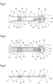
- FIGS. 1 and 2 illustrate a reversible leather goods belt 1, respectively in an open configuration and in a closed configuration, comprising a ribbon 2, a loop 3 mounted to slide on the ribbon 2, a buckle 4 mechanically secured in rotation relative to the ribbon 2 and a pin 5 mechanically secured in rotation relative to the ribbon 2 and relative to the buckle 4.
- the ribbon 2 has a first face 6 and a second face 7 opposite the first face 6.
- the first face 6 of the ribbon 2 has a first pattern and a first shade, while the second face of the ribbon has a second pattern different from the first pattern and a second shade different from the first shade.
- the ribbon 2 has a determined length and extends between a first end 8 and a second end 9 opposite the first end 8.
- the first end 8 does not have a fold of material on one of the first face 6 and second face 7 of the ribbon 2, such that the loop 3 is not blocked in a space provided by such a fold of material.
- the second end 9 of the ribbon 2 is free and arrowhead-shaped, and has curved edges.
- the strip 2 has a slot 10 extending from the first end 8 and opening onto the first face 6 and onto the second face 7.
- the slot 10 is configured to allow the barb 5 to be accessible both at the first face 6 and at the second face 7 of the ribbon 2 (see below in more detail).
- the ribbon 2 is provided with a first portion 11 having a first width and a second thinned portion 12 having a second width less than the first width.
- the second thinned portion 12 extends over a second determined length, for example between 1/10 and 1/5 of the determined length of the ribbon 2.
- the slot 10 of the ribbon 2 here extends only over the second thinned portion 12.
- first portion 11 and the second thinned portion 12 join at a first junction portion 13 having a variable width decreasing from the first portion 11 towards the second thinned portion 12.
- the first junction portion 13 here has a beveled edge.
- the ribbon 2 is provided with a third thinned portion 14 having a third width less than the first width of the first portion 11 and extending from the second end 9.
- the third thinned portion 14 and the second thinned portion 12 are here separated by the first portion 11.
- the third width of the third thinned portion 14 is substantially identical to the second width of the second thinned portion 12.
- the third thinned portion 14 and the first portion 11 join at a second junction portion 15.
- the second junction portion 15 here has a variable width which decreases from the first portion 11 towards the third thinned portion 14, and a beveled edge.
- the strip 2 comprises a plurality of through holes 16, which are provided opening onto the first face 6 and onto the second face 7 and at a distance from each other according to a determined gap from the second end 9.
- the strip 2 here comprises five through holes 16, which are provided in the third thinned portion 14.
- Each through hole 16 is configured to receive the pin 5 when the second end 9 of the ribbon 2 is inserted into the buckle 4, so as to close the leather goods belt 1 ( figure 2 ).
- the loop 3 is mounted mobile in translation on the second thinned portion 12 of the strip 2 and is accessible both from the first face 6 and from the second face 7 of the strip 2.
- the loop 3 is interposed between the loop 4 and the first portion 11 of the ribbon 2 such that the loop 3 is movable in translation only on the second thinned portion 12 of the ribbon 2, and here in particular between the loop 4 and the first joining portion 13 of the ribbon 2.
- the loop 3 is configured to hold the ribbon 2 at its second end 9 against the second thinned portion 12.
- the loop 4 is mechanically secured in rotation to the first end 8 of the ribbon 2.
- the barb 5 is mechanically secured in rotation to the first end 8 of the ribbon 2 and is movable relative to the loop 4 and through the slot 10 of the ribbon 2.
- the barb 5 can pass through the slot 10 from one to the other of the first face 6 and second face 7 of the ribbon 2, so that the barb 5 can come into abutment against the loop 4 on the side of the first face 6 or the second face 7 of the ribbon 2.
- the buckle 4 and the pin 5 form a mechanism for opening and closing the reversible leather goods belt 1.
- the second end 9 of the ribbon 2 is located at a distance from the first end 8 and is not introduced into the loop 4.
- the second end 9 of the ribbon 2 is introduced into the loop 4 and the loop 3, and the barb 5 is introduced into a through hole 16 chosen from the plurality of through holes 16 and is in contact against the loop 4.
- the strip 2 has a determined thickness over its determined length, which is formed from a first strip of material and a second strip of material.
- the first strip of material has the first face 6 of the ribbon 2 and the second strip of material has the second face 7 of the ribbon 2.
- the first strip of material and the second strip of material are arranged against each other and mechanically secured to each other, with the loop 4 being partially sandwiched between the first strip of material and the second strip of material, at the first end 8 of the ribbon 2.
- first strip of material and the second strip of material are made in a single piece folded back on itself with the loop 4 which is here sandwiched at a fold 17.
- first strip of material and the second strip of material are here symmetrical to each other.
- the fold 17 formed by the first strip of material and the second strip of material defines the first end 8 of the ribbon 2.
- the slot 10 passes through both the first strip of material and the second strip of material.
- first strip of material and the second strip of material are sewn to each other by a first sewing line 18 near the edges of the tape 2 and along the determined length of the tape 2.
- the slot 10 is partially surrounded by a second stitching line 19, called an additional stitching line.
- the second stitching line 19 is configured to mechanically secure the first strip of material and the second strip of material of the ribbon 2 locally around the slit 10.
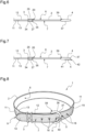
- the loop 3 is provided with a closed structure of material defining a through-hole 20 having a substantially rectangular shape having a first depth dimension greater than twice the determined thickness of the ribbon 2, and a second width dimension greater than the second width of the second thinned portion 12 and less than the first width of the first portion 11 of the ribbon 2.
- the through-orifice 20 is configured to accommodate the second thinned portion 12, so as to form with the first face 6 of the ribbon 2 a first space for receiving the second end 9 of the ribbon 2, and to form with the second face 7 of the ribbon 2 a second space for receiving the second end 9 of the ribbon 2.
- the loop 3 comprises a first H-shaped member 21 located on the first face 6 of the ribbon 2 and a second H-shaped member 22 located on the second face 7 of the ribbon 2.
- the first H-shaped member 21 and the second H-shaped member 22 each comprise a first branch 25, a second branch 26 parallel to the first branch 25 and a third branch 27 joining, in particular here in a median manner, the first branch 25 and the second branch 26.
- the first branch 25 of each of the first H-shaped member 21 and the second H-shaped member 22 has a first end and a second end opposite the first end.
- the second branch 26 of each of the first H-shaped member 21 and the second H-shaped member 22 has a third end and a fourth end opposite the third end.
- first end and the second end of the first branch 25 of the first H-shaped member 21 are aligned with each other along the length of the ribbon 2, while the first end and the second end of the first branch 25 of the second H-shaped member 22 are aligned with each other along the width of the ribbon 2.
- the third end and the fourth end of the second branch 26 of the first H-shaped member 21 are here aligned with each other along the length of the ribbon 2, while the third end and the fourth end of the second branch 26 of the second H-shaped member 22 are here aligned with each other along the width of the ribbon 2.
- the loop 3 further comprises a plurality of bridges each joining the first H-shaped member 21 located on the first face 6 and the second H-shaped member 22 located on the second face 7 of the ribbon 2.
- the plurality of bridges here comprises a first bridge 32 joining the first branch 25 of the first H-shaped member 21 to the first branch 25 of the second H-shaped member 22, a second bridge 33 adjacent to the first bridge 32 and joining the first branch 25 of the first H-shaped member 21 to the second branch 26 of the second H-shaped member 22, a third bridge 34 opposite the first bridge 32 and joining the second branch 26 of the first H-shaped member 21 to the first branch 25 of the second H-shaped member 22, and a fourth bridge 35 opposite the second bridge 33, adjacent to the third bridge 34 and joining the second branch 26 of the first H-shaped member 21 to the second branch 26 of the second H-shaped member 22.
- first bridge 32 joins the first end of the first H-shaped member 21 and the first end of the second H-shaped member 22
- the second bridge 33 joins the second end of the first H-shaped member 21 and the third end of the second H-shaped member 22
- third bridge 34 joins the third end of the first H-shaped member 21 and the second end of the second H-shaped member
- the fourth bridge 35 joins the fourth end of the first H-shaped member 21 and the fourth end of the second H-shaped member 22.
- the loop 4 is formed of a frame 36 comprising a first portion 37 in the shape of a horseshoe arch and having a first end 38 and a second end 39 opposite the first end 38, and a second straight portion (not visible in the drawings) Figures 1 to 8 ) joining the first end 38 and the second end 39 of the first portion 37 in the shape of a horseshoe arch and being mechanically secured in rotation to the first end 38 of the ribbon 2.
- the first horseshoe-shaped portion 37 and the second straight portion delimit an opening 40 for introducing the second end 6 of the ribbon 2 into the frame 36 of the loop 4.
- the barb 5 comprises a rod 41 having a first free end 42 and a second end 43 opposite the first end 42, and a mounting portion 44 extending from the second end 43.
- the first free end 42 of the tongue 5 is configured to come into abutment against the buckle 4, and in particular on the side of the first face 6 or on the side of the second face 7.
- the mounting portion 44 is configured to be mechanically secured to the second straight portion of the frame 36 of the loop 4.
- the mounting portion 44 is provided with a through mounting hole (not visible on the Figures 1 to 8 ), which is configured to accommodate the second straight portion of the frame 36 of the buckle 4, so as to mechanically secure in rotation the pin 5 to the buckle 4.
- the tongue 5 is in a first position in abutment against the loop 4 on the side of the first face 6 of the ribbon 2, and in particular against the first portion 37 in the shape of a horseshoe arch of the frame 36 of the loop 4.
- the pin 5 is rotated almost 180° from its first position in the figure 5 , and is located in a second position in slot 10 of ribbon 2.
- the pin 5 is rotated again by almost 180° relative to its second position in the figure 6 , always in the same direction of rotation, so as to completely pass through the slot 10 of the ribbon 2 and come into a third position abutting against the loop 4 on the side of the second face 7 of the ribbon 2, and in particular against the first portion 37 in the shape of a horseshoe arch of the frame 36 of the loop 4.
- the reversible leather goods belt 1 is in a closed configuration as illustrated in the figure 2 but with the second face 7 as the visible face instead of the first face 6 of the ribbon 2, and that this change of visible face is made possible in particular by the movement of the barb 5 as described above.
- the reversible leather goods belt 1 described above therefore combines the fact of having the tongue 5 movable through the slot 10 made in the ribbon 2 as well as the second thinned portion 12 of the ribbon 2 along which the loop 3 is movable in translation.
- Such a combination allows the leather goods belt 1 to be used reversibly, while simplifying its manufacture and use.
- the first side of the ribbon may have a first pattern and a first shade and the second side of the ribbon may have a second pattern identical to the first pattern and a second shade different from the first shade.
- the first side of the ribbon may have a first pattern and a first shade and the second side of the ribbon may have a second pattern different from the first pattern and a second shade identical to the first shade.
- the first strip of material and the second strip of material may be distinct from each other and joined to the first free, unfolded end of the ribbon by an addition of material at least partially covering the loop.
- the first joining portion may have a curved edge or any suitable shape.
- the slit may extend over the second thinned portion and the first portion of the ribbon.
- the ribbon may be provided with at least a third thinned portion having a third width less than the first width of the first portion and being interposed between two sections of the first portion.
- the second joining portion may have a curved edge or any other shape.
- the leather goods belt may further comprise at least one second loop mounted movable in translation on the at least one third thinned portion.
- the loop here can be formed from a frame having a rectangular shape or any other shape.
- the buckle may have a mounting portion folded around the second straight portion of the buckle frame.
Landscapes
- Engineering & Computer Science (AREA)
- Textile Engineering (AREA)
- Purses, Travelling Bags, Baskets, Or Suitcases (AREA)
- Treatment And Processing Of Natural Fur Or Leather (AREA)
- Buckles (AREA)
Applications Claiming Priority (1)
| Application Number | Priority Date | Filing Date | Title |
|---|---|---|---|
| FR2308282A FR3151746B1 (fr) | 2023-07-31 | 2023-07-31 | Ceinture de maroquinerie réversible |
Publications (2)
| Publication Number | Publication Date |
|---|---|
| EP4501157A1 true EP4501157A1 (de) | 2025-02-05 |
| EP4501157B1 EP4501157B1 (de) | 2026-03-04 |
Family
ID=88291245
Family Applications (1)
| Application Number | Title | Priority Date | Filing Date |
|---|---|---|---|
| EP24188902.1A Active EP4501157B1 (de) | 2023-07-31 | 2024-07-16 | Umkehrbarer ledergürtel |
Country Status (3)
| Country | Link |
|---|---|
| EP (1) | EP4501157B1 (de) |
| CN (1) | CN119423433A (de) |
| FR (1) | FR3151746B1 (de) |
Citations (5)
| Publication number | Priority date | Publication date | Assignee | Title |
|---|---|---|---|---|
| US2396329A (en) * | 1944-03-14 | 1946-03-12 | Celanese Corp | Belt |
| US2586457A (en) * | 1949-08-10 | 1952-02-19 | Hickok Mfg Co Inc | Stretchable belt |
| US2676379A (en) | 1952-06-19 | 1954-04-27 | Hornreich Samuel | Reversible buckle |
| US3026533A (en) * | 1960-06-01 | 1962-03-27 | Zakarin David | Swivel attachment for reversible belt |
| FR1467174A (fr) * | 1965-12-14 | 1967-01-27 | Laffargue & Fils S | Ceinture perfectionnée |
-
2023
- 2023-07-31 FR FR2308282A patent/FR3151746B1/fr active Active
-
2024
- 2024-07-16 EP EP24188902.1A patent/EP4501157B1/de active Active
- 2024-07-24 CN CN202410993217.0A patent/CN119423433A/zh active Pending
Patent Citations (5)
| Publication number | Priority date | Publication date | Assignee | Title |
|---|---|---|---|---|
| US2396329A (en) * | 1944-03-14 | 1946-03-12 | Celanese Corp | Belt |
| US2586457A (en) * | 1949-08-10 | 1952-02-19 | Hickok Mfg Co Inc | Stretchable belt |
| US2676379A (en) | 1952-06-19 | 1954-04-27 | Hornreich Samuel | Reversible buckle |
| US3026533A (en) * | 1960-06-01 | 1962-03-27 | Zakarin David | Swivel attachment for reversible belt |
| FR1467174A (fr) * | 1965-12-14 | 1967-01-27 | Laffargue & Fils S | Ceinture perfectionnée |
Also Published As
| Publication number | Publication date |
|---|---|
| EP4501157B1 (de) | 2026-03-04 |
| FR3151746B1 (fr) | 2025-07-25 |
| CN119423433A (zh) | 2025-02-14 |
| FR3151746A1 (fr) | 2025-02-07 |
Similar Documents
| Publication | Publication Date | Title |
|---|---|---|
| EP2604140B1 (de) | Verdrehsicherungs-Kettenglied | |
| EP1177742B1 (de) | Kosmetikdose mit verdecktem Scharnier | |
| EP1800559B1 (de) | Verbindung enthaltend ein Befestigungsgehäuse mit unterer Platte und oberer Platte | |
| EP2862469B1 (de) | Vorrichtung mit Schnalle zum Regulieren und Festziehen eines Gurts | |
| EP1646297B1 (de) | Bandförmiges verbindungsteil, insbesondere uhrarmband, das durch abschneiden gekürzt werden kann | |
| FR2713896A1 (fr) | Monture de barrette. | |
| WO2015185831A1 (fr) | Monture de lunettes a branches en lames de métal amovibles clipsees | |
| EP0549979B1 (de) | Gliederarmband, insbesondere für Uhren | |
| EP4501157B1 (de) | Umkehrbarer ledergürtel | |
| EP3565431B1 (de) | Verbindungsvorrichtung für armband | |
| CH667979A5 (en) | Adjustable fastener for bracelet - has curved central plate having groove in which arm of one part slides and locks in notches in groove | |
| EP2552270B1 (de) | Vorrichtung zum verschliessen und befestigen zweier längen einer biegsamen umreifung | |
| FR2472356A1 (fr) | Bande d'accrochage pour fermeture a glissiere | |
| FR2704120A1 (fr) | Fermoir dépliant pour bracelet. | |
| EP3949790B1 (de) | Gürtelschnalle, die sich an mindestens zwei gürtelbreiten anpassen lässt, und gürtel mit einer solchen schnalle | |
| FR3025614A1 (fr) | Monture de lunettes d'un nouveau type | |
| CH307499A (fr) | Poignée amovible. | |
| FR2484216A1 (fr) | Boucle autobloquante pour sangles | |
| FR3040266B1 (fr) | Curseur perfectionne pour fermeture a glissiere | |
| FR3163535A1 (fr) | Boucle de ceinture, notamment de maroquinerie, et ceinture, notamment de maroquinerie, comportant une telle boucle | |
| EP4530430A1 (de) | Vorrichtung zum halten von endkappen von rolladenblättern | |
| EP0287475B1 (de) | Verstellbare Befestigungseinrichtung für ein Armbandende, insbesondere für ein Uhrenarmband | |
| CH705839B1 (fr) | Maillon anti-rotation. | |
| EP3219220A1 (de) | Einstellvorrichtung für armband | |
| EP4167021A1 (de) | Brillengestell mit einem speziellen scharnier |
Legal Events
| Date | Code | Title | Description |
|---|---|---|---|
| PUAI | Public reference made under article 153(3) epc to a published international application that has entered the european phase |
Free format text: ORIGINAL CODE: 0009012 |
|
| STAA | Information on the status of an ep patent application or granted ep patent |
Free format text: STATUS: THE APPLICATION HAS BEEN PUBLISHED |
|
| AK | Designated contracting states |
Kind code of ref document: A1 Designated state(s): AL AT BE BG CH CY CZ DE DK EE ES FI FR GB GR HR HU IE IS IT LI LT LU LV MC ME MK MT NL NO PL PT RO RS SE SI SK SM TR |
|
| P01 | Opt-out of the competence of the unified patent court (upc) registered |
Free format text: CASE NUMBER: APP_17466/2025 Effective date: 20250410 |
|
| STAA | Information on the status of an ep patent application or granted ep patent |
Free format text: STATUS: REQUEST FOR EXAMINATION WAS MADE |
|
| 17P | Request for examination filed |
Effective date: 20250707 |
|
| GRAP | Despatch of communication of intention to grant a patent |
Free format text: ORIGINAL CODE: EPIDOSNIGR1 |
|
| STAA | Information on the status of an ep patent application or granted ep patent |
Free format text: STATUS: GRANT OF PATENT IS INTENDED |
|
| RIC1 | Information provided on ipc code assigned before grant |
Ipc: A41F 9/00 20060101AFI20250909BHEP Ipc: A41D 15/00 20060101ALI20250909BHEP |
|
| INTG | Intention to grant announced |
Effective date: 20251008 |
|
| GRAS | Grant fee paid |
Free format text: ORIGINAL CODE: EPIDOSNIGR3 |
|
| GRAA | (expected) grant |
Free format text: ORIGINAL CODE: 0009210 |
|
| STAA | Information on the status of an ep patent application or granted ep patent |
Free format text: STATUS: THE PATENT HAS BEEN GRANTED |
|
| AK | Designated contracting states |
Kind code of ref document: B1 Designated state(s): AL AT BE BG CH CY CZ DE DK EE ES FI FR GB GR HR HU IE IS IT LI LT LU LV MC ME MK MT NL NO PL PT RO RS SE SI SK SM TR |
|
| REG | Reference to a national code |
Ref country code: CH Ref legal event code: F10 Free format text: ST27 STATUS EVENT CODE: U-0-0-F10-F00 (AS PROVIDED BY THE NATIONAL OFFICE) Effective date: 20260304 Ref country code: GB Ref legal event code: FG4D Free format text: NOT ENGLISH |
|
| REG | Reference to a national code |
Ref country code: IE Ref legal event code: FG4D Free format text: LANGUAGE OF EP DOCUMENT: FRENCH |
|
| REG | Reference to a national code |
Ref country code: DE Ref legal event code: R096 Ref document number: 602024002963 Country of ref document: DE |