EP4501196A1 - Reinigungsvorrichtung - Google Patents
Reinigungsvorrichtung Download PDFInfo
- Publication number
- EP4501196A1 EP4501196A1 EP24191376.3A EP24191376A EP4501196A1 EP 4501196 A1 EP4501196 A1 EP 4501196A1 EP 24191376 A EP24191376 A EP 24191376A EP 4501196 A1 EP4501196 A1 EP 4501196A1
- Authority
- EP
- European Patent Office
- Prior art keywords
- dust collection
- wall
- cleaning device
- collection means
- cleaning
- Prior art date
- Legal status (The legal status is an assumption and is not a legal conclusion. Google has not performed a legal analysis and makes no representation as to the accuracy of the status listed.)
- Granted
Links
Images








Classifications
-
- A—HUMAN NECESSITIES
- A47—FURNITURE; DOMESTIC ARTICLES OR APPLIANCES; COFFEE MILLS; SPICE MILLS; SUCTION CLEANERS IN GENERAL
- A47L—DOMESTIC WASHING OR CLEANING; SUCTION CLEANERS IN GENERAL
- A47L7/00—Suction cleaners adapted for additional purposes; Tables with suction openings for cleaning purposes; Containers for cleaning articles by suction; Suction cleaners adapted to cleaning of brushes; Suction cleaners adapted to taking-up liquids
- A47L7/02—Suction cleaners adapted for additional purposes; Tables with suction openings for cleaning purposes; Containers for cleaning articles by suction; Suction cleaners adapted to cleaning of brushes; Suction cleaners adapted to taking-up liquids with driven tools for special purposes
-
- A—HUMAN NECESSITIES
- A47—FURNITURE; DOMESTIC ARTICLES OR APPLIANCES; COFFEE MILLS; SPICE MILLS; SUCTION CLEANERS IN GENERAL
- A47L—DOMESTIC WASHING OR CLEANING; SUCTION CLEANERS IN GENERAL
- A47L11/00—Machines for cleaning floors, carpets, furniture, walls, or wall coverings
- A47L11/40—Parts or details of machines not provided for in groups A47L11/02 - A47L11/38, or not restricted to one of these groups, e.g. handles, arrangements of switches, skirts, buffers, levers
- A47L11/4013—Contaminants collecting devices, i.e. hoppers, tanks or the like
- A47L11/4016—Contaminants collecting devices, i.e. hoppers, tanks or the like specially adapted for collecting fluids
-
- A—HUMAN NECESSITIES
- A47—FURNITURE; DOMESTIC ARTICLES OR APPLIANCES; COFFEE MILLS; SPICE MILLS; SUCTION CLEANERS IN GENERAL
- A47L—DOMESTIC WASHING OR CLEANING; SUCTION CLEANERS IN GENERAL
- A47L11/00—Machines for cleaning floors, carpets, furniture, walls, or wall coverings
- A47L11/02—Floor surfacing or polishing machines
- A47L11/20—Floor surfacing or polishing machines combined with vacuum cleaning devices
- A47L11/201—Floor surfacing or polishing machines combined with vacuum cleaning devices with supply of cleaning agents
-
- A—HUMAN NECESSITIES
- A47—FURNITURE; DOMESTIC ARTICLES OR APPLIANCES; COFFEE MILLS; SPICE MILLS; SUCTION CLEANERS IN GENERAL
- A47L—DOMESTIC WASHING OR CLEANING; SUCTION CLEANERS IN GENERAL
- A47L11/00—Machines for cleaning floors, carpets, furniture, walls, or wall coverings
- A47L11/28—Floor-scrubbing machines, motor-driven
-
- A—HUMAN NECESSITIES
- A47—FURNITURE; DOMESTIC ARTICLES OR APPLIANCES; COFFEE MILLS; SPICE MILLS; SUCTION CLEANERS IN GENERAL
- A47L—DOMESTIC WASHING OR CLEANING; SUCTION CLEANERS IN GENERAL
- A47L11/00—Machines for cleaning floors, carpets, furniture, walls, or wall coverings
- A47L11/40—Parts or details of machines not provided for in groups A47L11/02 - A47L11/38, or not restricted to one of these groups, e.g. handles, arrangements of switches, skirts, buffers, levers
-
- A—HUMAN NECESSITIES
- A47—FURNITURE; DOMESTIC ARTICLES OR APPLIANCES; COFFEE MILLS; SPICE MILLS; SUCTION CLEANERS IN GENERAL
- A47L—DOMESTIC WASHING OR CLEANING; SUCTION CLEANERS IN GENERAL
- A47L11/00—Machines for cleaning floors, carpets, furniture, walls, or wall coverings
- A47L11/40—Parts or details of machines not provided for in groups A47L11/02 - A47L11/38, or not restricted to one of these groups, e.g. handles, arrangements of switches, skirts, buffers, levers
- A47L11/4002—Installations of electric equipment
-
- A—HUMAN NECESSITIES
- A47—FURNITURE; DOMESTIC ARTICLES OR APPLIANCES; COFFEE MILLS; SPICE MILLS; SUCTION CLEANERS IN GENERAL
- A47L—DOMESTIC WASHING OR CLEANING; SUCTION CLEANERS IN GENERAL
- A47L11/00—Machines for cleaning floors, carpets, furniture, walls, or wall coverings
- A47L11/40—Parts or details of machines not provided for in groups A47L11/02 - A47L11/38, or not restricted to one of these groups, e.g. handles, arrangements of switches, skirts, buffers, levers
- A47L11/4013—Contaminants collecting devices, i.e. hoppers, tanks or the like
-
- A—HUMAN NECESSITIES
- A47—FURNITURE; DOMESTIC ARTICLES OR APPLIANCES; COFFEE MILLS; SPICE MILLS; SUCTION CLEANERS IN GENERAL
- A47L—DOMESTIC WASHING OR CLEANING; SUCTION CLEANERS IN GENERAL
- A47L11/00—Machines for cleaning floors, carpets, furniture, walls, or wall coverings
- A47L11/40—Parts or details of machines not provided for in groups A47L11/02 - A47L11/38, or not restricted to one of these groups, e.g. handles, arrangements of switches, skirts, buffers, levers
- A47L11/4027—Filtering or separating contaminants or debris
-
- A—HUMAN NECESSITIES
- A47—FURNITURE; DOMESTIC ARTICLES OR APPLIANCES; COFFEE MILLS; SPICE MILLS; SUCTION CLEANERS IN GENERAL
- A47L—DOMESTIC WASHING OR CLEANING; SUCTION CLEANERS IN GENERAL
- A47L11/00—Machines for cleaning floors, carpets, furniture, walls, or wall coverings
- A47L11/40—Parts or details of machines not provided for in groups A47L11/02 - A47L11/38, or not restricted to one of these groups, e.g. handles, arrangements of switches, skirts, buffers, levers
- A47L11/4036—Parts or details of the surface treating tools
-
- A—HUMAN NECESSITIES
- A47—FURNITURE; DOMESTIC ARTICLES OR APPLIANCES; COFFEE MILLS; SPICE MILLS; SUCTION CLEANERS IN GENERAL
- A47L—DOMESTIC WASHING OR CLEANING; SUCTION CLEANERS IN GENERAL
- A47L11/00—Machines for cleaning floors, carpets, furniture, walls, or wall coverings
- A47L11/40—Parts or details of machines not provided for in groups A47L11/02 - A47L11/38, or not restricted to one of these groups, e.g. handles, arrangements of switches, skirts, buffers, levers
- A47L11/4063—Driving means; Transmission means therefor
- A47L11/4069—Driving or transmission means for the cleaning tools
-
- A—HUMAN NECESSITIES
- A47—FURNITURE; DOMESTIC ARTICLES OR APPLIANCES; COFFEE MILLS; SPICE MILLS; SUCTION CLEANERS IN GENERAL
- A47L—DOMESTIC WASHING OR CLEANING; SUCTION CLEANERS IN GENERAL
- A47L11/00—Machines for cleaning floors, carpets, furniture, walls, or wall coverings
- A47L11/40—Parts or details of machines not provided for in groups A47L11/02 - A47L11/38, or not restricted to one of these groups, e.g. handles, arrangements of switches, skirts, buffers, levers
- A47L11/408—Means for supplying cleaning or surface treating agents
-
- A—HUMAN NECESSITIES
- A47—FURNITURE; DOMESTIC ARTICLES OR APPLIANCES; COFFEE MILLS; SPICE MILLS; SUCTION CLEANERS IN GENERAL
- A47L—DOMESTIC WASHING OR CLEANING; SUCTION CLEANERS IN GENERAL
- A47L11/00—Machines for cleaning floors, carpets, furniture, walls, or wall coverings
- A47L11/40—Parts or details of machines not provided for in groups A47L11/02 - A47L11/38, or not restricted to one of these groups, e.g. handles, arrangements of switches, skirts, buffers, levers
- A47L11/408—Means for supplying cleaning or surface treating agents
- A47L11/4083—Liquid supply reservoirs; Preparation of the agents, e.g. mixing devices
-
- A—HUMAN NECESSITIES
- A47—FURNITURE; DOMESTIC ARTICLES OR APPLIANCES; COFFEE MILLS; SPICE MILLS; SUCTION CLEANERS IN GENERAL
- A47L—DOMESTIC WASHING OR CLEANING; SUCTION CLEANERS IN GENERAL
- A47L11/00—Machines for cleaning floors, carpets, furniture, walls, or wall coverings
- A47L11/40—Parts or details of machines not provided for in groups A47L11/02 - A47L11/38, or not restricted to one of these groups, e.g. handles, arrangements of switches, skirts, buffers, levers
- A47L11/4094—Accessories to be used in combination with conventional vacuum-cleaning devices
-
- A—HUMAN NECESSITIES
- A47—FURNITURE; DOMESTIC ARTICLES OR APPLIANCES; COFFEE MILLS; SPICE MILLS; SUCTION CLEANERS IN GENERAL
- A47L—DOMESTIC WASHING OR CLEANING; SUCTION CLEANERS IN GENERAL
- A47L9/00—Details or accessories of suction cleaners, e.g. mechanical means for controlling the suction or for effecting pulsating action; Storing devices specially adapted to suction cleaners or parts thereof; Carrying-vehicles specially adapted for suction cleaners
-
- A—HUMAN NECESSITIES
- A47—FURNITURE; DOMESTIC ARTICLES OR APPLIANCES; COFFEE MILLS; SPICE MILLS; SUCTION CLEANERS IN GENERAL
- A47L—DOMESTIC WASHING OR CLEANING; SUCTION CLEANERS IN GENERAL
- A47L9/00—Details or accessories of suction cleaners, e.g. mechanical means for controlling the suction or for effecting pulsating action; Storing devices specially adapted to suction cleaners or parts thereof; Carrying-vehicles specially adapted for suction cleaners
- A47L9/02—Nozzles
Definitions
- the present invention relates to the field of household appliances, in particular to a cleaning device, such as a vacuum cleaner, a mopping apparatus or a floor sweeper.
- a cleaning device such as a vacuum cleaner, a mopping apparatus or a floor sweeper.
- Cleaning devices are generally fitted with a dust bin for collecting dust and other dirt.
- a fluid communication duct is generally provided between the dust bin and a body of the device, the duct allowing air or dust and other dirt to pass through.
- a sealing member may be provided at the position of connection between the dust bin and the device body to prevent outward leakage of gases or dust.
- Existing sealing members are quite complex in structure, and usually need to be fitted to both the device body and the dust bin by insertion, in order to ensure sealing quality, but such a configuration makes removal of the dust bin from the device body inconvenient. Sealing members which are structurally simple can be envisaged, but structurally simple sealing members are likely to result in a poor sealing effect, fatigue damage after a long period of use, and so on.
- existing cleaning devices have room for improvement in other respects, for example: there are few alignment feature structures between the dust bin and the device body, so deviation from the correct installation position is likely to occur in the process of installing the dust bin; a sealing structure between a handle and the device body is overly complex, making removal of the handle from the device difficult; a connection structure for fitting a cleaning fluid tank, used for holding cleaning fluid, to the device is difficult to operate; a mounting bracket for a vibrating component motor has too simple a structure, so the motor is easily damaged in use and has a short service life; and a suction cleaning part of the cleaning device contains complex ducts and electric wires, so components for accommodating or carrying these ducts and electric wires usually need to be additionally provided, which increases the overall volume of the structure as well as the manufacturing cost.
- the present invention provides a cleaning device, with a sealing member provided in a region of connection of a body part and a dust collection component of the cleaning device, a cross section of an elastic force application portion of the sealing member being formed in an arc shape, thereby enabling a good sealing effect while also facilitating installation and removal of the dust collection component; moreover, the sealing member has a two-layer elastic wall structure and is therefore not likely to deform even with long-term use.
- the cleaning device of the present invention also provides preferred configurations in other respects; for example, the present invention additionally provides an alignment structure between the dust collection component and a device body, further avoiding problems such as rocking and shifting during installation of the dust collection component; improves a sealing structure between a handle and the device body, facilitating installation and removal of the handle; improves an installation connection structure of a cleaning fluid storage tank and the device body, facilitating installation and removal of the cleaning fluid storage tank; improves the structure of a motor mounting bracket, avoiding excessive rocking of the motor during use, and thus being able to effectively extend the motor service life; and integrates part of a wall face of a cleaning apparatus with a part for accommodating and carrying electric wires, ducts and other structures, thus saving space and reducing manufacturing costs.
- a cleaning device comprising:
- the sealing member comprises a mounting portion fixed to the body top portion, the mounting portion being connected to a top end of the outside wall, and a top end of the inside wall being a free end.
- the inside wall and the outside wall are formed in a shape, such as an annular shape, fitting the shape of the second gas channel port, and in particular, an axial dimension of the inside wall is substantially equal to an axial dimension of the outside wall.
- a sectional profile of the connecting wall forms a substantially arc-shaped portion, such as a semicircle, a 1/4 circle or a teardrop shape, and preferably, the top wall is at a certain angle to a longitudinal direction of the cleaning device.
- the dust collection means has an inlet in communication with the cleaning apparatus, a filtration component positioned between the inlet and the second gas channel port is further provided in the dust collection means, and a gas suction apparatus is provided in the body top portion, the gas suction apparatus being used to suck gas from the dust collection means into the body top portion via the second gas channel port and the first gas channel port.
- a first positioning feature structure is provided on the dust collection means at a position of connection to the body side portion, and the body side portion has a second positioning feature structure corresponding to the first positioning feature structure, wherein the first positioning feature structure and the second positioning feature structure are positioned so that in the process of installing the dust collection means, the first positioning feature structure and the second positioning feature structure begin to engage with each other when the top wall of the dust collection means comes close to the sealing member.
- the first positioning feature structure is a rib that is positioned on the dust collection means near the bottom and projects in a first horizontal direction towards the body side portion
- the second positioning feature structure is a rib receiving slot of depth 3 mm; in particular, the rib comprises two ribs arranged side by side in a second horizontal direction perpendicular to the first horizontal direction, and the rib receiving slot is one slot running through in the second horizontal direction.
- a positioning slot extending in a first horizontal direction is provided at the bottom of the dust collection means, and a positioning protrusion corresponding to the positioning slot is provided on a top surface of the body bottom portion; and/or a positioning block protruding towards a bottom side is provided on the dust collection means at a position close to the bottom and remote from the body side portion, a receiving recess corresponding to the positioning block is provided on the body bottom portion, and preferably, an outer surface of the positioning block is flush with an outer surface of the body bottom portion when the dust collection means is mounted on the body.
- the cleaning device comprises an elongated handle detachably mounted on the body top portion, wherein a second sealing member is mounted at a handle receiving port of the body top portion, the second sealing member having a sealing portion abutting an outer periphery of the handle, and in a cross section through a centre line of the handle, a sectional profile of the sealing portion is formed in a circular arc shape, in particular a semicircle, a 1/4 circle, or a teardrop shape.
- the sealing portion comprises a top wall, a bottom wall, and a transitional portion which smoothly connects radial inner ends of the top wall and the bottom wall, a radial outer end of the top wall being fixed to the body top portion, and a radial outer end of the bottom wall being free.
- the body top portion contains a first support member and a second support member located at the bottom of the first support member, the second sealing member being located in an accommodating space jointly defined by the first support member and the second support member, and preferably, the handle has a locking pin projecting radially from an outer wall thereof, and the first support member is provided with a locking pin hole corresponding to the locking pin, the locking pin hole being spaced apart from the accommodating space.
- a cleaning fluid storage means is fitted to the body top portion, and a locking bolt and a button fixedly connected to the locking bolt are provided at the top of the cleaning fluid storage means, the locking bolt being constructed to be movable, under the driving action of the button, between a locked position in which the locking bolt extends into the body top portion and an unlocked position in which the locking bolt is disengaged from the body top portion;
- an elastic member is provided between the locking bolt and a body of the cleaning fluid storage means, and when the locking bolt is in the unlocked position, the elastic member stores force, and has a biasing force that biases the locking bolt towards the locked position; in particular, the locking bolt and the button are a one-piece member.
- the cleaning fluid storage means has a bottom cover assembly, with a retainer provided at the bottom of the bottom cover assembly, the retainer having a top opening to partially install and accommodate the bottom cover assembly; a cleaning fluid discharge tube extending towards a bottom side is provided at the bottom of the retainer, and the retainer has two opposite wing parts projecting horizontally, the wing parts being received in corresponding accommodating parts in the body top portion, such that the retainer is pivotable.
- the wing parts are hollow round tube structures; more preferably, the two wing parts are coaxial but have different diameters, and more preferably, a bottom surface of the wing part with the larger diameter of the two wing parts is flush with a bottom surface of a body of the retainer;
- a one-way valve is provided on the bottom cover assembly, and the retainer has an installation post projecting towards a top side, the installation post being inserted into the bottom of a valve core of the one-way valve; preferably, a sealing ring is provided between the retainer and the bottom cover assembly, and the installation post is dimensioned so that sealing can be maintained at the sealing ring in the process of the installation post and the one-way valve interacting with each other during installation and removal of the cleaning fluid storage means.
- a motor and a motor mounting bracket are provided in the cleaning apparatus, wherein the motor mounting bracket comprises a mounting base and a circumferential portion which is annular and projects from the mounting base towards a top side, the circumferential portion surrounding the motor and being adapted in shape to the motor; preferably, the circumferential portion covers a region of the motor that exceeds 1/2 of an axial dimension thereof, and more preferably, the circumferential portion covers a region equivalent to 1/2 - 3/4 of the motor in the axial direction thereof.
- a connecting component constructed to allow the cleaning apparatus to pivot relative to the body is provided between the cleaning apparatus and the body, and the cleaning apparatus comprises a mounting bracket for receiving the connecting component, a part of the mounting bracket forming part of an outer surface of the cleaning apparatus, and the mounting bracket further comprising an extension portion in the cleaning apparatus, the extension portion being constructed to cover or carry an electric wire or duct in the cleaning apparatus, and the mounting bracket being an integrally formed member; in particular, there are two said extension portions, the two extension portions extending from a body of the mounting bracket in two partially opposite directions.
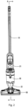
- the present invention provides a cleaning device, such as a vacuum cleaner, which in particular may be a vacuum cleaner with a mopping function. It should first be explained that directional and positional terms in the present invention should be understood as meaning relative directions and positions, and should be interpreted with reference to the normal orientation of the cleaning device in a state of use (e.g. Fig. 1 ).
- Figs. 1 - 16 show a cleaning device 100 according to some preferred embodiments of the present invention.
- the cleaning device 100 comprises a body 20, a handle 10 mounted at the top of the body 20, and a cleaning apparatus 50 mounted at the bottom of the body 20.
- a gripping portion 11 is formed at the top of the handle 10.
- the cleaning apparatus 50 is configured to directly contact a surface to be cleaned and is formed as a plate-like structure, which extends substantially along a horizontal plane when viewed from the angles shown in Figs. 1 and 2 , and which is pivotable relative to the body 20 in a position of use.
- the body 20 has a body top portion 21, a body bottom portion 23, and a body side portion 22 connected between the body top portion 21 and the body bottom portion 23.
- the cleaning device 100 further comprises a cleaning fluid storage means 40 mounted on the body top portion 21, and a dust collection means 30 mounted between the body top portion 21 and the body bottom portion 23.
- the dust collection means 30, the cleaning fluid storage means 40 and the body 20 together form a substantially tubular structure.
- the dust collection means 30 has two fluid channels respectively in communication with the body 20: a dirt inlet 31 formed on a side wall of the dust collection means 30, and a gas outlet 33 formed on a top wall 34 of the dust collection means 30.
- a dirt inlet 31 formed on a side wall of the dust collection means 30, and a gas outlet 33 formed on a top wall 34 of the dust collection means 30.
- an inlet 241 of a dust suction duct 24 of the cleaning device 100 is formed on the cleaning apparatus 50, specifically arranged near the bottom of the cleaning device 100; an outlet 242 of the dust suction duct 24 (see Fig. 8 ) is formed at an approximately central position on the body side portion 22 of the body 20, and in communication with the dirt inlet 31 of the dust collection means 30.
- a suction apparatus 211 such as a fan, is provided in the body top portion 21 of the body 20; the suction apparatus 211 sucks gas from the dust collection means 30 into the body top portion 31 through the gas outlet 33.
- a filtration means positioned between the dirt inlet 31 and the gas outlet 33 is provided in the dust collection means 30, the filtration means further comprising a primary filtration component 32 mainly used for filtering large particles and a secondary filtration component 36 mainly used for filtering small particles.
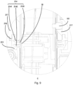
- Fig. 4 shows the structure of a sealing member 25 at a position of connection between the gas outlet 33 of the dust collection means 30 and a gas inlet 26 of the body top portion 31, the sealing member 25 for example being a sealing ring.
- the sealing member 25 as a whole is made of a soft elastic material such as silicone rubber, and has a mounting portion 251 for mounting the sealing member 25 and a sealing portion serving a sealing function.
- the mounting portion 251 is snap-fitted to the body top portion 21; the sealing portion comprises an annular inside wall 2522, an annular outside wall 2521, and a connecting wall 2523 connected at the bottom of the inside wall 2522 and the outside wall 2521.
- a top end of the outside wall 2521 is connected to the mounting portion 251, and a top end of the inside wall 2522 is a free end.
- the connecting wall 2523 is constructed to transition smoothly from a bottom end of the inside wall 2522 to a bottom end of the outside wall 2521; that is to say, there is no edge in a region of connection of the inside wall 2522 and the outside wall 2521.
- the sectional profile of the connecting wall 2523 is formed to be substantially semicircular.
- the sectional profile of the connecting wall 2523 may be formed in a teardrop shape, meaning that a radial dimension is largest near a bottommost part thereof and slightly smaller at a position slightly nearer the top.
- the sectional profile of the connecting wall 2523 may be formed in another arc shape, e.g. a 1/4 circle.
- the sealing member may not be a sealing ring.
- the sealing member may be a non-annular member, having an outside wall, an inside wall and an arc-shaped connecting wall, similar to the sealing member described above.
- the annular inside wall 2522 and the annular outside wall 2521 are both circular ring structures around an axis X1, and an axial dimension of the inside wall 2522 is substantially equal to an axial dimension of the outside wall 2521.
- the sealing member 25 has a shape adapted to the shape of the gas outlet 33 overall; for example, the inside wall and outside wall may be constructed in an oval or square shape, etc. if the gas outlet 33 is oval or square, and an axis of the inside and outside walls may be a straight line through the centre point of a projected profile thereof.
- the connecting wall 2523 of the sealing member 25 is configured to abut and be pressed tightly against the top wall 34 of the dust collection means 30 around the gas outlet 33.
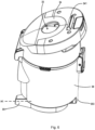
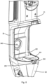
- Figs. 5 and 6 show views of the dust collection means 30 and the body 20 respectively after they have been separated.
- the sealing member 25 is pre-installed on the body top portion 21 of the body 20; when the dust collection means 30 is installed on the body 20, the sealing member 25 and the top wall 34 of the dust collection means 30 come into contact and are pressed tightly against each other, and there is no need for a snap-fitting or other connection relationship between the dust collection means 30 and the sealing member 25.
- Such a configuration of the sealing member 25 can achieve a good sealing effect while also facilitating installation and removal of the dust collection means 30. Moreover, the sealing member 25 is not likely to deform even with long-term use, due to having a two-layer elastic wall structure.
- the gas inlet 26 on the body top portion 21 forms a "first gas channel port", and the gas outlet 33 of the dust collection means 30 forms a "second gas channel port”.
- the first gas channel port and second gas channel port may be other channel ports; for example, the first gas channel port and second gas channel port may be the outlet of the dust suction duct and the dirt inlet of the dust collection means. That is to say, the sealing member in the embodiment described above could also be used at other positions where gas channel ports are joined.
- a locking tongue 341 is provided on the top wall 34 of the dust collection means 30, and a locking tongue receiving slot 212 is formed on a bottom wall of the body top portion 21.
- the dust collection means 30 and the body 20 have a variety of alignment feature structures, to facilitate accurate positioning of the dust collection means 30 in the process of installing the dust collection means 30, and avoid rocking or shifting of the dust collection means 30.
- a first positioning feature structure 351 is provided on the dust collection means 30 at a position of connection to the body side portion 22, and the body side portion 22 has a second positioning feature structure 221 corresponding to the first positioning feature structure 351.
- the first positioning feature structure 351 is a rib that is positioned on the dust collection means 30 near the bottom and projects in a first horizontal direction H1 towards a side wall; the second positioning feature structure 221 is the side wall.
- first positioning feature structure 351 and the second positioning feature structure 221 may be positioned such that: in the process of installing the dust collection means 30, the first positioning feature structure 351 and the second positioning feature structure 221 begin to engage with each other when the top of the dust collection means 30 comes close to the sealing member 25.
- a positioning slot 352 extending in the first horizontal direction H1 is provided at the bottom of the dust collection means 30, and a positioning protrusion 231 corresponding to the positioning slot 352 is provided on a top surface of the body bottom portion 23; a positioning block 353 protruding towards a bottom side is provided on the dust collection means 30 at a position close to the bottom and remote from the body side portion 22, and a receiving recess 232 corresponding to the positioning block is provided on the body bottom portion 23, the positioning protrusion 231 and the receiving recess 232 being separated by a separating wall 233.
- an outer surface of the positioning block 353 and an outer surface of the body bottom portion 23 are flush with each other.
- the positioning block 353 and the receiving recess 232 engage with each other first, and the dust collection means 30 pivots around the positioning block 353, such that the positioning slot 352 of the dust collection means 30 engages with the positioning protrusion 231, and the separating wall is thus positioned between the positioning block 353 and the positioning slot 352.
- the top wall 34 of the dust collection means 30 is about to come into contact with the sealing member 25, the rib and the side wall (i.e. the first positioning feature structure 351 and the second positioning feature structure 221) begin to engage with each other.
- the top wall 34 is at a certain angle to a vertical direction (i.e.
- first positioning feature structure and “second positioning feature structure” mentioned in the present invention are merely used to distinguish between components.
- the components may be named in different ways.
- the positioning block 353 may be called a first positioning part, while the receiving recess 232 is a first positioning counterpart corresponding to the first positioning part; and the part with reference numeral 351 may be called a second positioning part, while the part with reference numeral 221 is a second positioning counterpart corresponding to the second positioning part.
- a sealing structure between the handle 10 and the body 20 has a similar structure to the sealing member 25.
- the sealing structure between the handle 10 and the body 20 is called a second sealing member 216.
- the handle 10 is an elongated structure detachably mounted on the body top portion 21; the second sealing member 216 is mounted at a handle receiving port of the body top portion 21, and the second sealing member 216 has a sealing portion 214 abutting an outer periphery of the handle 10.
- the sectional profile of the sealing portion 214 is formed in a circular arc shape, e.g. a semicircle, a 1/4 circle, or a teardrop shape.
- the sealing portion comprises a top wall 2141, a bottom wall 2142, and a transitional portion 2143 which smoothly connects radial inner ends of the top wall 2141 and the bottom wall 2142.
- a radial outer end of the top wall 2141 is fixed to a mounting portion of the second sealing member 216, and a radial outer end of the bottom wall 2142 is free.
- the second sealing member 216 has the same advantages as the sealing member 25.
- the configuration of a second sealing ring can achieve a good sealing effect while also facilitating mounting and removal of the handle 10.
- the second sealing member 216 is not likely to deform even with long-term use, due to having a two-layer elastic wall structure.
- the second sealing member may have a non-annular shape; the non-annular second sealing member may still have a top wall, a bottom wall, and a transitional portion in a circular arc shape, as in the second sealing member described above.
- the body top portion contains a first support member 217 and a second support member 213 located at the bottom of the first support member.
- the second sealing member 214 is located in an accommodating space jointly defined by the first support member 217 and the second support member 213, and the mounting portion of the second sealing member 216 may be snap-fitted to the first support member 217 and/or the second support member 213.
- the handle has a locking pin 101 projecting radially from an outer wall thereof, and the first support member 217 is provided with a locking pin hole corresponding to the locking pin 101, the locking pin hole being spaced apart from the accommodating space, to prevent the locking pin 101 from interfering with the second sealing member 214.
- a locking bolt 41 and a button 42 fixedly connected to the locking bolt 41 are provided at the top of the cleaning fluid storage means 40, the locking bolt 41 being constructed to be movable, under the driving action of the button 42, between a locked position in which the locking bolt extends into a locking bolt receiving slot 222 of the body top portion 21 and an unlocked position in which the locking bolt is disengaged from the body top portion 21.
- an elastic member 43 is provided between the locking bolt 41 and a body 20 of the cleaning fluid storage means 40; when the locking bolt 41 is in the unlocked position, the elastic member 43 stores force, and has a biasing force that biases the locking bolt 41 towards the locked position.
- the locking bolt 41 and the button 42 may be integrally formed.
- the cleaning fluid storage means 40 is also provided with a one-way valve 44 near the top thereof, to enable the cleaning fluid storage means 40 to be replenished with air when the cleaning fluid is discharged.
- the cleaning fluid storage means 40 has a bottom cover assembly 45, with a retainer 47 provided at the bottom of the bottom cover assembly 45, the retainer 47 having a top opening to partially install and accommodate the bottom cover assembly 45.
- a one-way valve 46 is provided on the bottom cover assembly 45, and the retainer 47 has an installation post 471 projecting towards a top side, the installation post 471 being inserted into the bottom of a valve core of the one-way valve 46.
- a filtration core 475 is further provided in the retainer 47.
- a sealing ring is provided between the retainer 47 and the bottom cover assembly 45, and the installation post 471 is dimensioned so that sealing can be maintained at the sealing ring in the process of the installation post 471 and the one-way valve 46 interacting with each other during installation and removal of the cleaning fluid storage means 40.
- the 3D structure of the retainer 47 is shown in Fig. 12 .
- a cleaning fluid discharge tube 472 extending towards a bottom side is provided at the bottom of the retainer 47, and the retainer 47 has two opposite wing parts 473, 474 projecting horizontally.
- the two wing parts 473, 474 are hollow tubular structures, the two tubular structures having a common axis D1.
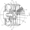
- Fig. 13 shows another sectional drawing of the components shown in Fig. 11 . This cross section is jointly defined by an axis X2 of the installation post and the axis D1 of the tubular structures formed by the wing parts 473, 474, and the two wing parts 473, 474 are shown in the sectional drawing.
- wing parts 473, 474 are received in corresponding accommodating parts 223 in the body top portion 21. Since the wing parts 473, 474 are tube structures and the accommodating parts 223 are cylindrical receiving cavities, the retainer 47 is rotatable as a whole through a certain angle about direction D1 (see Fig. 12 ), and this facilitates installation and removal of the cleaning fluid storage means 40. It will be understood that the pivoting and rocking of the retainer 47 used for receiving the cleaning fluid storage means 40 can provide an optimal engagement angle, facilitating alignment of the cleaning fluid storage means 40.
- the pair of wing parts 473, 474 have different diameters, and a bottom surface of the wing part 473 with the larger diameter is flush with a bottom surface of a body of the retainer 47.
- a motor 52 for providing vibration for the cleaning apparatus 50 is installed in the cleaning apparatus 50.
- a motor mounting bracket 53 may also have an improved structure.
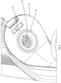
- Fig. 14 shows the motor mounting bracket 53 on a bottom cover 51 of the cleaning apparatus 50, the motor mounting bracket comprising a mounting base 531 and a circumferential portion 532 which is annular and projects from the mounting base 531 towards a top side, the circumferential portion 532 surrounding the motor 52 and being adapted in shape to the motor 52.
- the circumferential portion 532 covers a region of the motor 52 that exceeds 1/2 of an axial dimension thereof, and more preferably, the circumferential portion 532 covers a region equivalent to 1/2 - 3/4 of the motor 52 in the axial direction thereof.
- Such a configuration can avoid excessive rocking of the motor 52 during use, so can effectively extend the service life of the motor 52.
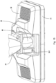
- a connecting component 60 constructed to allow the cleaning apparatus 50 to pivot relative to the body 20 is provided between the cleaning apparatus 50 and the body 20, and the cleaning apparatus 50 comprises a mounting bracket 54 for receiving the connecting component 60, the mounting bracket 54 being a one-piece member.
- a part 541 of the mounting bracket 54 forms part of an outer surface of the cleaning apparatus 50.
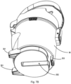
- Fig. 16 shows the structure of the cleaning apparatus 50 after removal of a top wall 34 and other components thereof; as can be seen, the mounting bracket 54 further comprises extension portions 542 in the cleaning apparatus 50, the extension portions 542 being constructed to cover or carry electric wires or ducts in the cleaning apparatus 50.
- embodiments of the present invention integrate part of a wall face of the cleaning apparatus 50 with a part for accommodating and carrying electric wires, ducts and other structures, thus saving space and reducing manufacturing costs.
- sealing in the region of connection of the dust collection component and the body part of the present invention can achieve a good sealing effect while also facilitating installation and removal of the dust collection component; moreover, the sealing member has a two-layer elastic wall structure and is therefore not likely to deform even with long-term use.
- the present invention additionally provides an alignment structure between the dust collection component and the device body, further avoiding problems such as rocking and shifting during installation of the dust collection component; improves the sealing structure between the handle and the device body, facilitating installation and removal of the handle; improves the installation connection structure of the cleaning fluid storage tank and the device body, facilitating installation and removal of the cleaning fluid storage tank; improves the structure of the motor mounting bracket, avoiding excessive rocking of the motor during use, and thus being able to effectively extend the motor service life; and integrates part of a wall face of the cleaning apparatus with a part for accommodating and carrying electric wires, ducts and other structures, thus saving space and reducing manufacturing costs.
Landscapes
- Engineering & Computer Science (AREA)
- Mechanical Engineering (AREA)
- Filtering Of Dispersed Particles In Gases (AREA)
Applications Claiming Priority (1)
| Application Number | Priority Date | Filing Date | Title |
|---|---|---|---|
| CN202310967783.XA CN119423608A (zh) | 2023-08-02 | 2023-08-02 | 清洁设备 |
Publications (3)
| Publication Number | Publication Date |
|---|---|
| EP4501196A1 true EP4501196A1 (de) | 2025-02-05 |
| EP4501196C0 EP4501196C0 (de) | 2025-12-10 |
| EP4501196B1 EP4501196B1 (de) | 2025-12-10 |
Family
ID=92039293
Family Applications (1)
| Application Number | Title | Priority Date | Filing Date |
|---|---|---|---|
| EP24191376.3A Active EP4501196B1 (de) | 2023-08-02 | 2024-07-29 | Reinigungsvorrichtung |
Country Status (4)
| Country | Link |
|---|---|
| US (1) | US20250040778A1 (de) |
| EP (1) | EP4501196B1 (de) |
| CN (1) | CN119423608A (de) |
| AU (1) | AU2024205138A1 (de) |
Citations (3)
| Publication number | Priority date | Publication date | Assignee | Title |
|---|---|---|---|---|
| CN108903783A (zh) * | 2018-09-30 | 2018-11-30 | 江苏美的清洁电器股份有限公司 | 干湿两用吸尘器 |
| AU2020100009A4 (en) * | 2019-01-07 | 2020-02-13 | Bissell Inc. | Surface cleaning apparatus having a fluid distributor |
| CN216293940U (zh) * | 2021-04-28 | 2022-04-15 | 宁波方太厨具有限公司 | 一种用于清洁机的灰尘分离模块及清洁机 |
-
2023
- 2023-08-02 CN CN202310967783.XA patent/CN119423608A/zh active Pending
-
2024
- 2024-07-26 AU AU2024205138A patent/AU2024205138A1/en active Pending
- 2024-07-29 EP EP24191376.3A patent/EP4501196B1/de active Active
- 2024-08-02 US US18/793,308 patent/US20250040778A1/en active Pending
Patent Citations (3)
| Publication number | Priority date | Publication date | Assignee | Title |
|---|---|---|---|---|
| CN108903783A (zh) * | 2018-09-30 | 2018-11-30 | 江苏美的清洁电器股份有限公司 | 干湿两用吸尘器 |
| AU2020100009A4 (en) * | 2019-01-07 | 2020-02-13 | Bissell Inc. | Surface cleaning apparatus having a fluid distributor |
| CN216293940U (zh) * | 2021-04-28 | 2022-04-15 | 宁波方太厨具有限公司 | 一种用于清洁机的灰尘分离模块及清洁机 |
Also Published As
| Publication number | Publication date |
|---|---|
| AU2024205138A1 (en) | 2025-02-20 |
| EP4501196C0 (de) | 2025-12-10 |
| US20250040778A1 (en) | 2025-02-06 |
| CN119423608A (zh) | 2025-02-14 |
| EP4501196B1 (de) | 2025-12-10 |
Similar Documents
| Publication | Publication Date | Title |
|---|---|---|
| CN104822301B (zh) | 电动吸尘器 | |
| EP3795049B1 (de) | Staubsauger | |
| US9155438B2 (en) | Extension pipe assembly for a vacuum cleaner | |
| CN105380560A (zh) | 电动吸尘器 | |
| EP4501196A1 (de) | Reinigungsvorrichtung | |
| KR20010049225A (ko) | 싸이클론 진공 청소기의 집진통 결합장치 | |
| CN107890323A (zh) | 用于吸尘器的旋风过滤器、尘杯和吸尘器 | |
| JP2014068749A (ja) | 電気掃除機 | |
| CN220369940U (zh) | 集尘站和具有其的集尘系统 | |
| CN116412561A (zh) | 一种气液分离器 | |
| US20050140137A1 (en) | Hose lock apparatus for vacuum cleaner | |
| CN219500929U (zh) | 接口组件及清洁设备 | |
| CN119523337A (zh) | 硬表面清洁设备 | |
| CN108937713B (zh) | 应用于吸尘器的装配结构及吸尘器 | |
| CN221813814U (zh) | 用于清洁设备的吸入清洁模块和清洁设备 | |
| CN221813815U (zh) | 清洁设备 | |
| CN220870331U (zh) | 一种软管快接接头 | |
| CN110367879A (zh) | 排风装置及设有其的吸尘器 | |
| KR200370520Y1 (ko) | 진공 청소기용 싸이클론 집진장치 | |
| CN211796208U (zh) | 一种直接放取式尘杯结构及其吸尘器 | |
| CN214595709U (zh) | 一种吸尘器及尘杯组件 | |
| KR100565579B1 (ko) | 진공 청소기용 흡입구체 | |
| CN120167823A (zh) | 清洁设备 | |
| KR0170854B1 (ko) | 진공청소기의 흡입구 | |
| KR100601422B1 (ko) | 진공청소기의 플랙시블 호스 결합구조 |
Legal Events
| Date | Code | Title | Description |
|---|---|---|---|
| PUAI | Public reference made under article 153(3) epc to a published international application that has entered the european phase |
Free format text: ORIGINAL CODE: 0009012 |
|
| STAA | Information on the status of an ep patent application or granted ep patent |
Free format text: STATUS: THE APPLICATION HAS BEEN PUBLISHED |
|
| AK | Designated contracting states |
Kind code of ref document: A1 Designated state(s): AL AT BE BG CH CY CZ DE DK EE ES FI FR GB GR HR HU IE IS IT LI LT LU LV MC ME MK MT NL NO PL PT RO RS SE SI SK SM TR |
|
| STAA | Information on the status of an ep patent application or granted ep patent |
Free format text: STATUS: REQUEST FOR EXAMINATION WAS MADE |
|
| 17P | Request for examination filed |
Effective date: 20250528 |
|
| GRAP | Despatch of communication of intention to grant a patent |
Free format text: ORIGINAL CODE: EPIDOSNIGR1 |
|
| STAA | Information on the status of an ep patent application or granted ep patent |
Free format text: STATUS: GRANT OF PATENT IS INTENDED |
|
| RIC1 | Information provided on ipc code assigned before grant |
Ipc: A47L 11/20 20060101AFI20250626BHEP Ipc: A47L 11/40 20060101ALI20250626BHEP |
|
| INTG | Intention to grant announced |
Effective date: 20250707 |
|
| GRAS | Grant fee paid |
Free format text: ORIGINAL CODE: EPIDOSNIGR3 |
|
| GRAA | (expected) grant |
Free format text: ORIGINAL CODE: 0009210 |
|
| STAA | Information on the status of an ep patent application or granted ep patent |
Free format text: STATUS: THE PATENT HAS BEEN GRANTED |
|
| AK | Designated contracting states |
Kind code of ref document: B1 Designated state(s): AL AT BE BG CH CY CZ DE DK EE ES FI FR GB GR HR HU IE IS IT LI LT LU LV MC ME MK MT NL NO PL PT RO RS SE SI SK SM TR |
|
| REG | Reference to a national code |
Ref country code: CH Ref legal event code: F10 Free format text: ST27 STATUS EVENT CODE: U-0-0-F10-F00 (AS PROVIDED BY THE NATIONAL OFFICE) Effective date: 20251210 Ref country code: GB Ref legal event code: FG4D |
|
| REG | Reference to a national code |
Ref country code: DE Ref legal event code: R096 Ref document number: 602024001625 Country of ref document: DE |
|
| REG | Reference to a national code |
Ref country code: IE Ref legal event code: FG4D |
|
| U01 | Request for unitary effect filed |
Effective date: 20260109 |
|
| U07 | Unitary effect registered |
Designated state(s): AT BE BG DE DK EE FI FR IT LT LU LV MT NL PT RO SE SI Effective date: 20260115 |
|
| PG25 | Lapsed in a contracting state [announced via postgrant information from national office to epo] |
Ref country code: ES Free format text: LAPSE BECAUSE OF FAILURE TO SUBMIT A TRANSLATION OF THE DESCRIPTION OR TO PAY THE FEE WITHIN THE PRESCRIBED TIME-LIMIT Effective date: 20251210 |
|
| PG25 | Lapsed in a contracting state [announced via postgrant information from national office to epo] |
Ref country code: NO Free format text: LAPSE BECAUSE OF FAILURE TO SUBMIT A TRANSLATION OF THE DESCRIPTION OR TO PAY THE FEE WITHIN THE PRESCRIBED TIME-LIMIT Effective date: 20260310 |
|
| PG25 | Lapsed in a contracting state [announced via postgrant information from national office to epo] |
Ref country code: HR Free format text: LAPSE BECAUSE OF FAILURE TO SUBMIT A TRANSLATION OF THE DESCRIPTION OR TO PAY THE FEE WITHIN THE PRESCRIBED TIME-LIMIT Effective date: 20251210 |
|
| PG25 | Lapsed in a contracting state [announced via postgrant information from national office to epo] |
Ref country code: RS Free format text: LAPSE BECAUSE OF FAILURE TO SUBMIT A TRANSLATION OF THE DESCRIPTION OR TO PAY THE FEE WITHIN THE PRESCRIBED TIME-LIMIT Effective date: 20260310 |